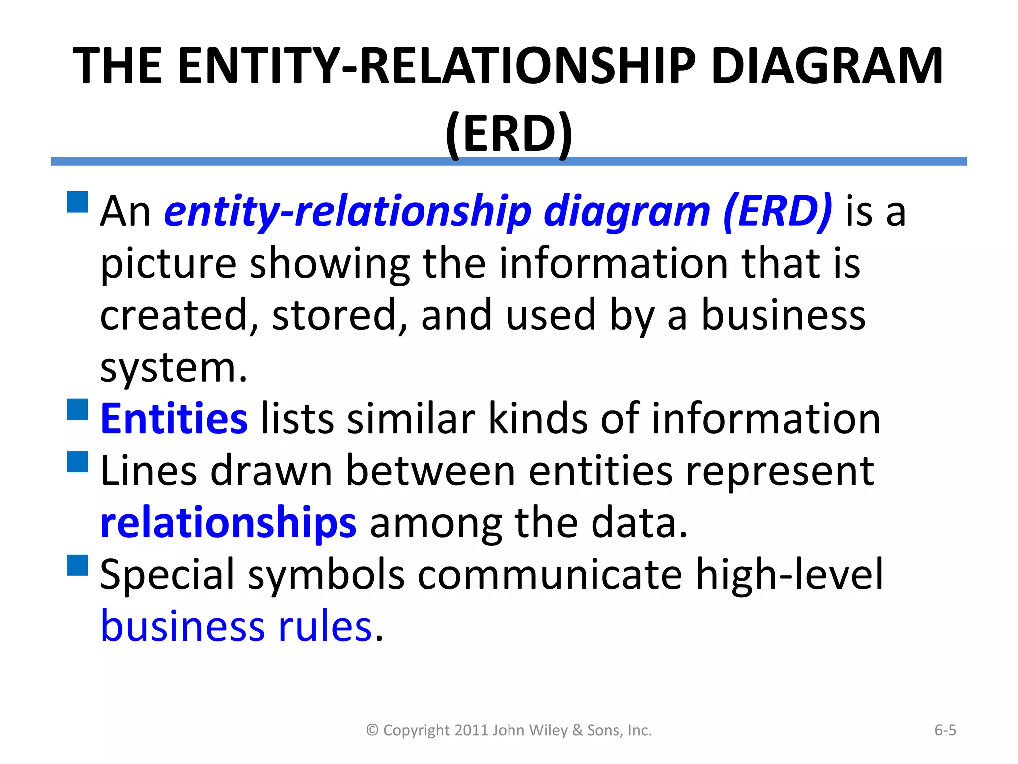
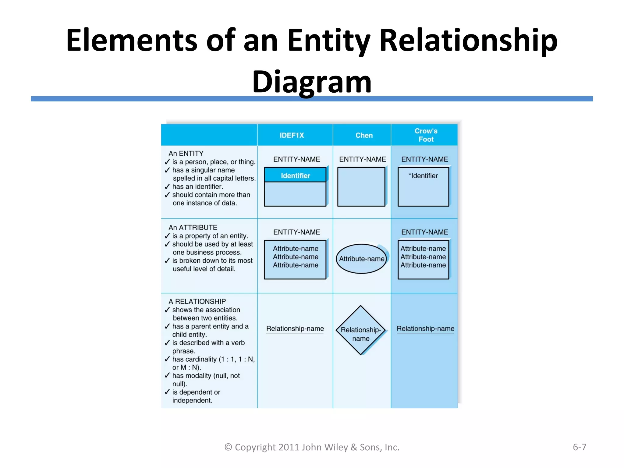
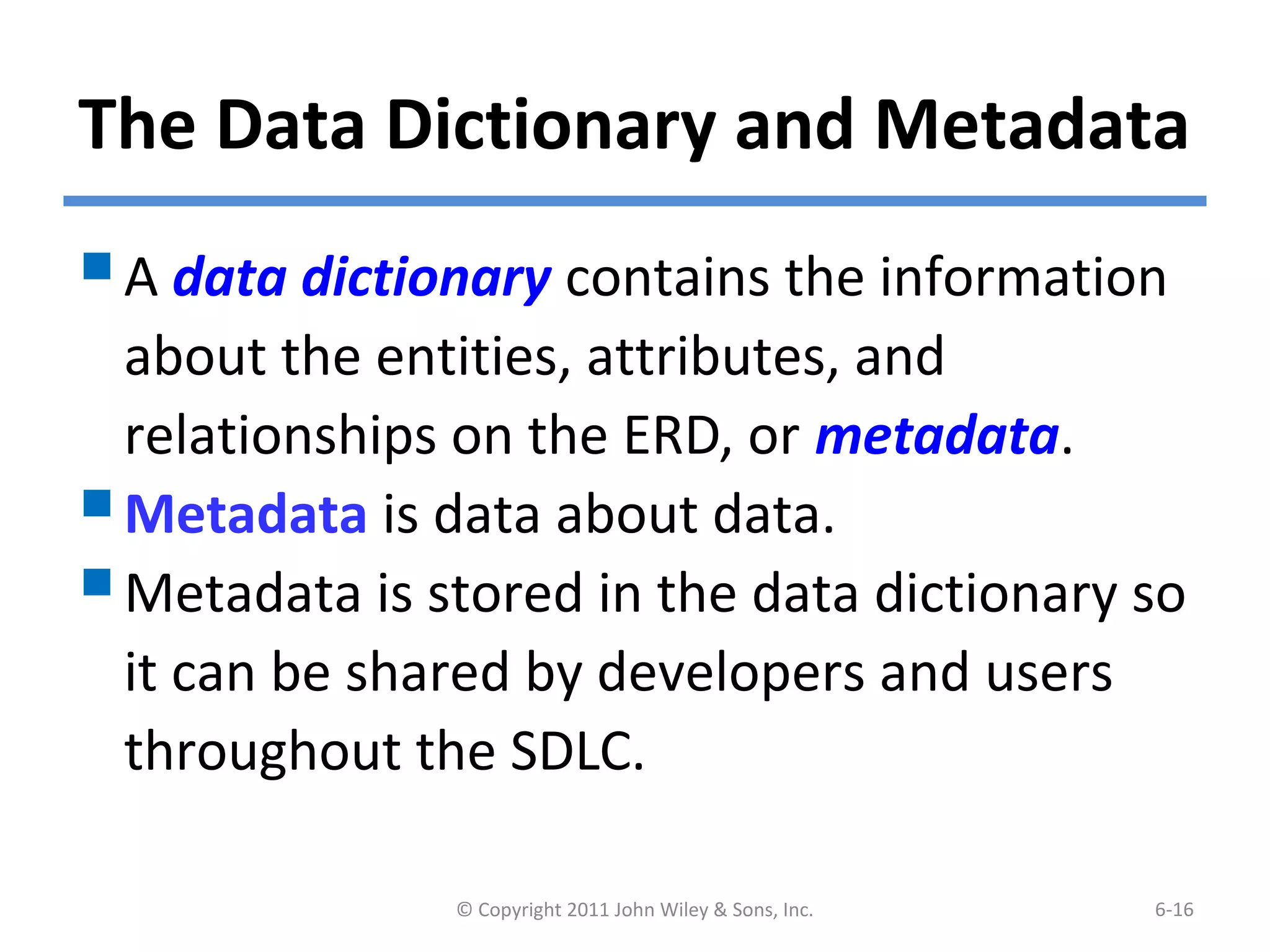
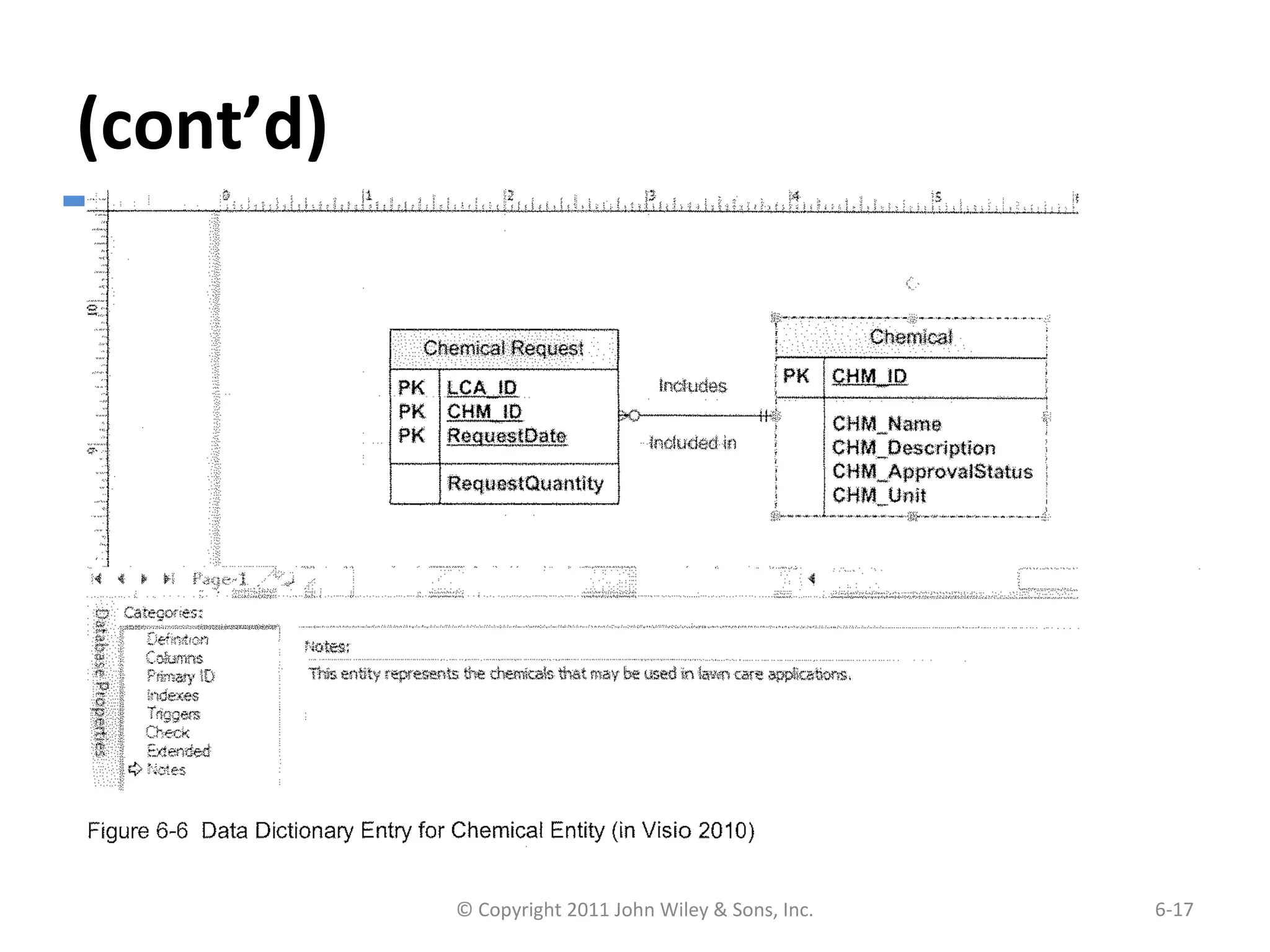
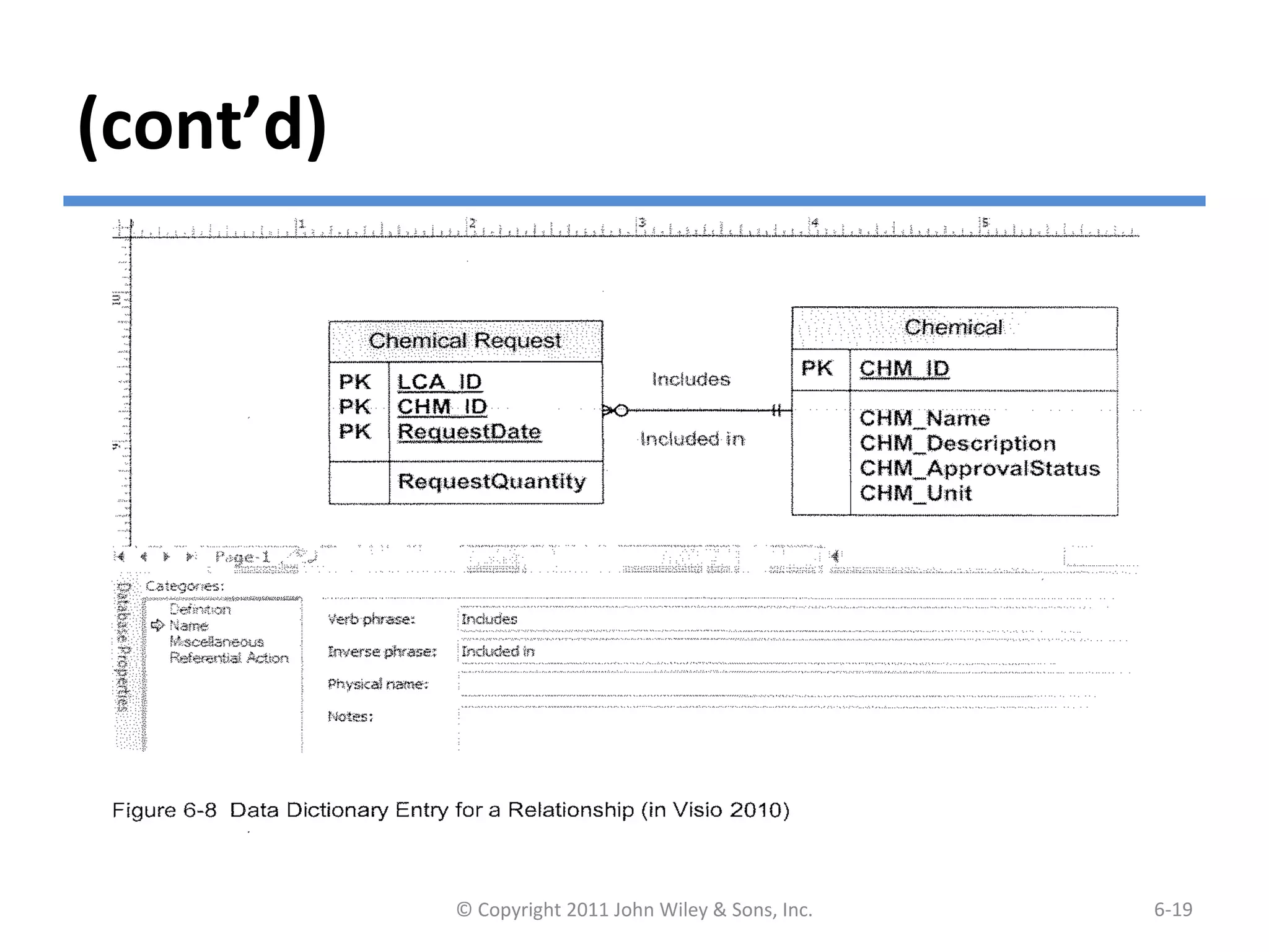
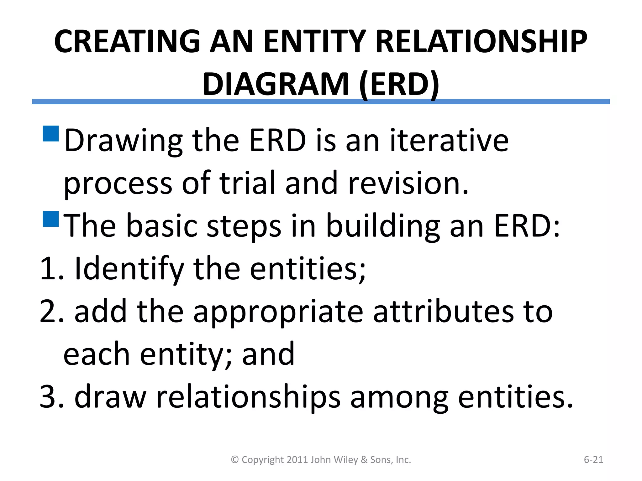
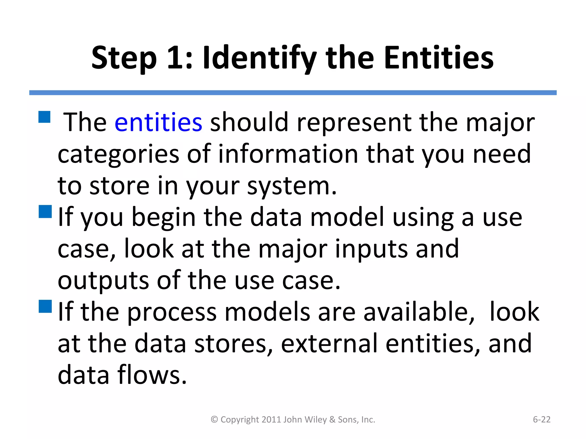
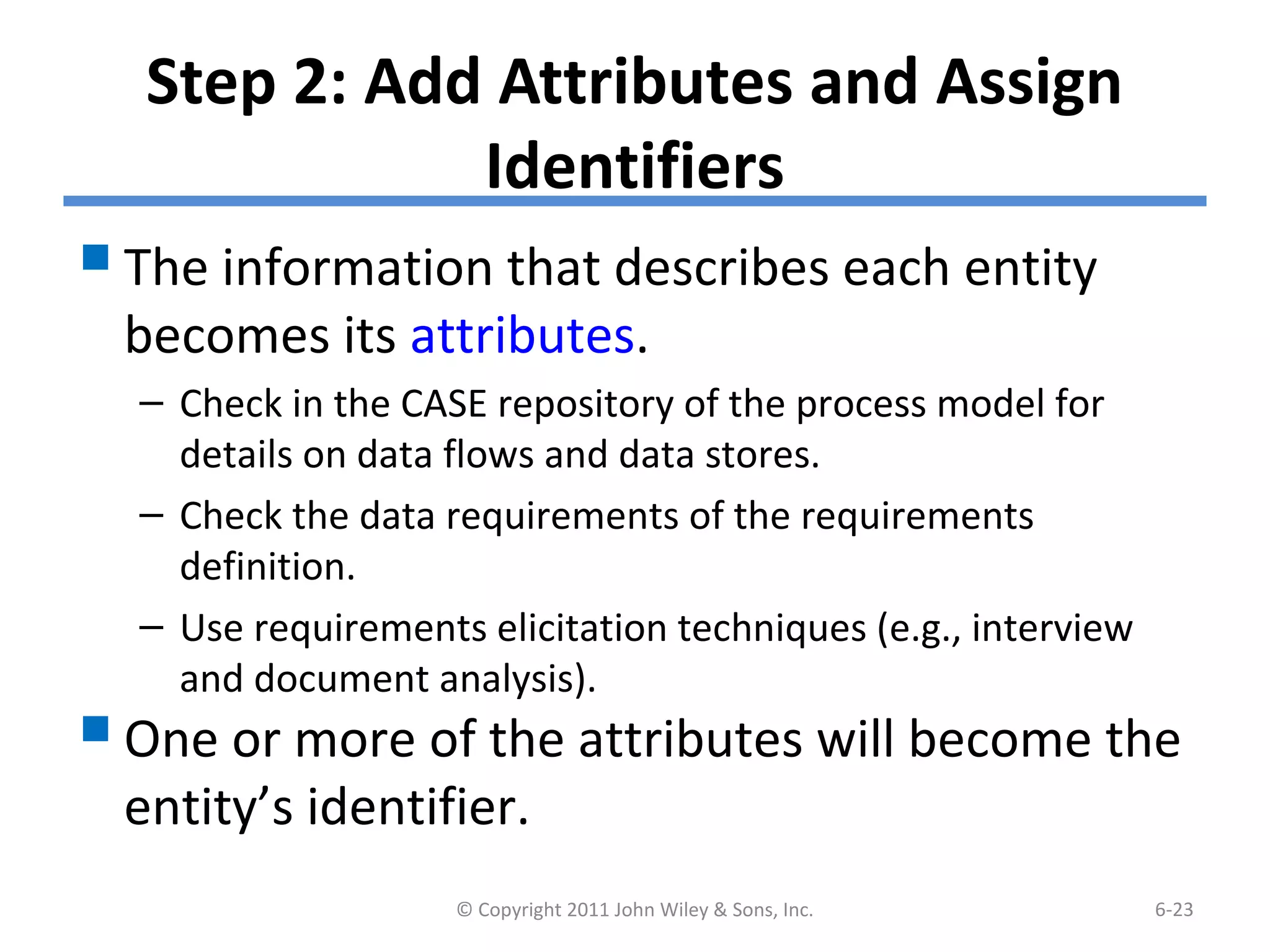
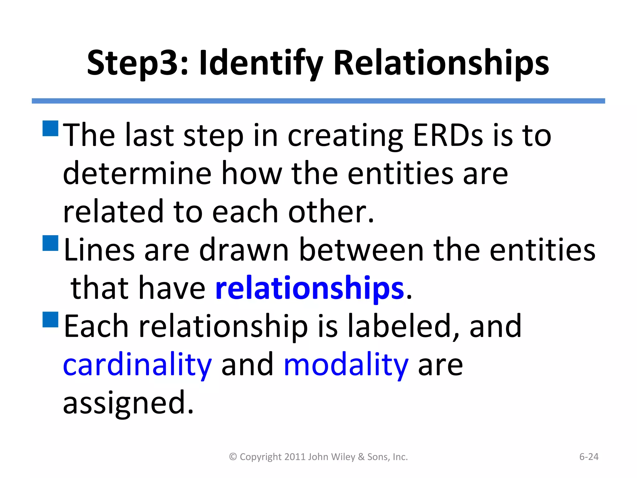
Systems Analysis and DesignSystems Analysis and Design
5th Edition5th Edition
Chapter 6. Data ModelingChapter 6. Data Modeling
Alan Dennis, Barbara Haley Wixom, and Roberta Roth
6-1© Copyright 2011 John Wiley & Sons, Inc.
Chapter 6 Outline
 The Entity Relationship Diagram
(ERD).
- Elements of ERD
- The Data Dictionary and Metadata
 Creating an Entity Relationship
Diagram.
 Validating an ERD.
© Copyright 2011 John Wiley & Sons, Inc. 6-2
INTRODUCTION
 In this chapter, we discuss how the data are
organized and presented.
 A data model is a formal way of representing the
data that are used and created by a business system.
 During analysis (this Chapter), analysts draw a
Logical data model which shows the logical
organization of data without indicating how it is
stored, created, or manipulated.
 During design (Chapter 11), analysts draw a physical
data model to reflect how the data will physically be
stored in databases or files.
© Copyright 2011 John Wiley & Sons, Inc. 6-3
(cont’d)
 Topics of this chapter:
- Creating an entity relationship diagram
(ERD).
- Normalization, a technique that helps
analysts validate the data models.
- How data models balance, or
interrelate, with the process models.
© Copyright 2011 John Wiley & Sons, Inc. 6-4
THE ENTITY-RELATIONSHIP DIAGRAM
(ERD)
An entity-relationship diagram (ERD) is a
picture showing the information that is
created, stored, and used by a business
system.
Entities lists similar kinds of information
Lines drawn between entities represent
relationships among the data.
Special symbols communicate high-level
business rules.
© Copyright 2011 John Wiley & Sons, Inc. 6-5
Reading an Entity Relationship
Diagram
© Copyright 2011 John Wiley & Sons, Inc. 6-6
Elements of an Entity Relationship
Diagram
© Copyright 2011 John Wiley & Sons, Inc. 6-7
Entity
The entity is the basic building block for
a data model. It is a person, place,
event, or thing about which data is
collected.
 Entities represent something for which
there exist multiple instances, or
occurrences.
- E.g., John Smith could be an instance of the
customer entity.
© Copyright 2011 John Wiley & Sons, Inc. 6-8
(cont’d)
© Copyright 2011 John Wiley & Sons, Inc. 6-9
Attributes
An attribute is some type of information that
is captured about an entity.
Attributes are nouns that are listed with an
entity.
One or more attributes can serve as the entity
identifier - the attribute(s) that can uniquely
identify one instance of an entity.
Concatenated identifier - several attributes
are combined to uniquely identify an instance.
© Copyright 2011 John Wiley & Sons, Inc. 6-10
(cont’d)
© Copyright 2011 John Wiley & Sons, Inc. 6-11
Choices for Identifiers
Relationships
Relationships are associations
between entities.
Every relationship has a parent
entity and a child entity.
Relationships should be labeled with
active verbs.
© Copyright 2011 John Wiley & Sons, Inc. 6-12
Cardinality
 A relationship has cardinality which is the ratio of
parent instances to child instances.
 The 1:1 relationship means that one instance of the
parent entity is associated with one instance of the
child entity.
 The 1:N relationship means that a single instance of
a parent entity is associated with many instances of a
child entity.
 The M:N relationship means that many instances of
a parent entity can relate to many instances of a
child entity.
© Copyright 2011 John Wiley & Sons, Inc. 6-13
(cont’d)
Example of M:N Relationship
© Copyright 2011 John Wiley & Sons, Inc. 6-14
Modality
A relationship has modality of null or not null,
which refers to whether or not an instance of a
child entity can exist without a related instance in
the parent entity.
Null means that an instance of a child entity can
exist without a related instance in the parent
entity.
Not Null means that an instance of a child entity
can’t exist without a related instance in the
parent entity.
© Copyright 2011 John Wiley & Sons, Inc. 6-15
The Data Dictionary and Metadata
A data dictionary contains the information
about the entities, attributes, and
relationships on the ERD, or metadata.
Metadata is data about data.
Metadata is stored in the data dictionary so
it can be shared by developers and users
throughout the SDLC.
© Copyright 2011 John Wiley & Sons, Inc. 6-16
(cont’d)
Example of Data Dictionary Entry for
Entity
© Copyright 2011 John Wiley & Sons, Inc. 6-17
(cont’d)
Example of Data Dictionary Entry for
Attributes
© Copyright 2011 John Wiley & Sons, Inc. 6-18
(cont’d)
Example of Data Dictionary of Entry
for Relationship
© Copyright 2011 John Wiley & Sons, Inc. 6-19
(cont’d)
Types of Metadata Captured by the
Data Dictionary
© Copyright 2011 John Wiley & Sons, Inc. 6-20
CREATING AN ENTITY RELATIONSHIP
DIAGRAM (ERD)
Drawing the ERD is an iterative
process of trial and revision.
The basic steps in building an ERD:
1. Identify the entities;
2. add the appropriate attributes to
each entity; and
3. draw relationships among entities.
© Copyright 2011 John Wiley & Sons, Inc. 6-21
Step 1: Identify the Entities
 The entities should represent the major
categories of information that you need
to store in your system.
If you begin the data model using a use
case, look at the major inputs and
outputs of the use case.
If the process models are available, look
at the data stores, external entities, and
data flows.
© Copyright 2011 John Wiley & Sons, Inc. 6-22
Step 2: Add Attributes and Assign
Identifiers
The information that describes each entity
becomes its attributes.
– Check in the CASE repository of the process model for
details on data flows and data stores.
– Check the data requirements of the requirements
definition.
– Use requirements elicitation techniques (e.g., interview
and document analysis).
One or more of the attributes will become the
entity’s identifier.
© Copyright 2011 John Wiley & Sons, Inc. 6-23
Step3: Identify Relationships
The last step in creating ERDs is to
determine how the entities are
related to each other.
Lines are drawn between the entities
that have relationships.
Each relationship is labeled, and
cardinality and modality are
assigned.
© Copyright 2011 John Wiley & Sons, Inc. 6-24
Advanced Syntax
Three special types of entities:
Independent Entity
–Can exist without the help of another
entity.
–The identifiers is created from the entity’s
own attributes.
–Attributes from other entities are not
needed to uniquely identify instances of
these entities.
© Copyright 2011 John Wiley & Sons, Inc. 6-25
(cont’d)
Dependent Entity
– There are situations when a child entity does
require attributes from the parent entity to
uniquely identify an instance. In these cases,
the child entity is called a dependent entity, and
its identifier consists of at least one attributes
from the parent entity.
(E.g., the Chemical Request entity in Figure 6.1).
© Copyright 2011 John Wiley & Sons, Inc. 6-26
(cont’d)
Intersection Entity
–It exists in order to capture some
information about the relationship
between two other entities. Typically,
intersection entities are added to a
data model to store information about
two entities sharing an M : N
relationship.
© Copyright 2011 John Wiley & Sons, Inc. 6-27
(cont’d)
There are three steps involved in adding an
intersection entity:
Step 1. Remove the M:N relationship line and
insert a new entity (intersection entity) in
between the two existing ones.
Step 2. Add two 1:N relationships to the
model.
Step 3. Name the intersection entity.
© Copyright 2011 John Wiley & Sons, Inc. 6-28
(cont’d)
Resolving an M:N Relationship
© Copyright 2011 John Wiley & Sons, Inc. 6-29
VALIDATING AN ERD
 General design guidelines.
 Normalization.
Check the ERD against the process
models to make sure that both
model balance each other.
© Copyright 2011 John Wiley & Sons, Inc. 6-30
Design Guidelines
© Copyright 2011 John Wiley & Sons, Inc. 6-31
Normalization
Normalization is a technique that
can help analysts validate the data
models.
It is a process whereby a series of
rules are applied to a logical data
model to determine how well
formed it is.
© Copyright 2011 John Wiley & Sons, Inc. 6-32
(cont’d)
Normalization Steps
© Copyright 2011 John Wiley & Sons, Inc. 6-33
Balancing ERDs with DFDs
 The process models and data models are
interrelated.
 Although the process model focuses on the business
processes, it contains two data components – the
data and the data store.
 These two data components of the DFDs need to
balance with the ERDs.
 The DFD data components need to correspond with
the ERD’s data stores (i.e., entities) and the data
elements that comprise the data flows (i.e.,
attributes) depicted on the data model.
© Copyright 2011 John Wiley & Sons, Inc. 6-34
(cont’d)
 Many CASE tools provide features of identifying
problems with balance between DFDs and ERDs;
however, it is important to understand how to
identify problems on your own.
 Check your DFDs and ERDs to make sure all data
components correspond between DFDs and ERDs.
 A useful tools to clearly depict the interrelationship
between process and data models is the CRUD
matrix (create, read, update, delete matrix).
© Copyright 2011 John Wiley & Sons, Inc. 6-35
(cont’d)
A Portion of a DFD and the CRUD Matrix
© Copyright 2011 John Wiley & Sons, Inc. 6-36
SUMMARY
 Basic Entity Relationship Diagram Syntax
- Entity describes people, places, or things.
- Attribute is some type of information about the entity.
- Relationship conveys the associations between entities.
 Creating an ERD
- Identify the entities.
- Add the attributes to each entity.
- Draw relationships among entities.
 Validating an ERD
- Normalization
- CRUD matrix
© Copyright 2011 John Wiley & Sons, Inc. 6-37
Copyright 2011 John Wiley & Sons, Inc.
All rights reserved. Reproduction or translation of this work
beyond that permitted in Section 117 of the 1976 United States
Copyright Act without the express written permission of the
copyright owner is unlawful. Request for further information
should be addressed to the Permissions Department, John Wiley
& Sons, Inc. The purchaser may make back-up copies for his/her
own use only and not for redistribution or resale. The Publisher
assumes no responsibility for errors, omissions, or damages,
caused by the use of these programs or from the use of the
information contained herein.
© Copyright 2011 John Wiley & Sons, Inc. 6-38

Datamodelling

  • 1.
    Systems Analysis andDesignSystems Analysis and Design 5th Edition5th Edition Chapter 6. Data ModelingChapter 6. Data Modeling Alan Dennis, Barbara Haley Wixom, and Roberta Roth 6-1© Copyright 2011 John Wiley & Sons, Inc.
  • 2.
    Chapter 6 Outline The Entity Relationship Diagram (ERD). - Elements of ERD - The Data Dictionary and Metadata  Creating an Entity Relationship Diagram.  Validating an ERD. © Copyright 2011 John Wiley & Sons, Inc. 6-2
  • 3.
    INTRODUCTION  In thischapter, we discuss how the data are organized and presented.  A data model is a formal way of representing the data that are used and created by a business system.  During analysis (this Chapter), analysts draw a Logical data model which shows the logical organization of data without indicating how it is stored, created, or manipulated.  During design (Chapter 11), analysts draw a physical data model to reflect how the data will physically be stored in databases or files. © Copyright 2011 John Wiley & Sons, Inc. 6-3
  • 4.
    (cont’d)  Topics ofthis chapter: - Creating an entity relationship diagram (ERD). - Normalization, a technique that helps analysts validate the data models. - How data models balance, or interrelate, with the process models. © Copyright 2011 John Wiley & Sons, Inc. 6-4
  • 5.
    THE ENTITY-RELATIONSHIP DIAGRAM (ERD) Anentity-relationship diagram (ERD) is a picture showing the information that is created, stored, and used by a business system. Entities lists similar kinds of information Lines drawn between entities represent relationships among the data. Special symbols communicate high-level business rules. © Copyright 2011 John Wiley & Sons, Inc. 6-5
  • 6.
    Reading an EntityRelationship Diagram © Copyright 2011 John Wiley & Sons, Inc. 6-6
  • 7.
    Elements of anEntity Relationship Diagram © Copyright 2011 John Wiley & Sons, Inc. 6-7
  • 8.
    Entity The entity isthe basic building block for a data model. It is a person, place, event, or thing about which data is collected.  Entities represent something for which there exist multiple instances, or occurrences. - E.g., John Smith could be an instance of the customer entity. © Copyright 2011 John Wiley & Sons, Inc. 6-8
  • 9.
    (cont’d) © Copyright 2011John Wiley & Sons, Inc. 6-9
  • 10.
    Attributes An attribute issome type of information that is captured about an entity. Attributes are nouns that are listed with an entity. One or more attributes can serve as the entity identifier - the attribute(s) that can uniquely identify one instance of an entity. Concatenated identifier - several attributes are combined to uniquely identify an instance. © Copyright 2011 John Wiley & Sons, Inc. 6-10
  • 11.
    (cont’d) © Copyright 2011John Wiley & Sons, Inc. 6-11 Choices for Identifiers
  • 12.
    Relationships Relationships are associations betweenentities. Every relationship has a parent entity and a child entity. Relationships should be labeled with active verbs. © Copyright 2011 John Wiley & Sons, Inc. 6-12
  • 13.
    Cardinality  A relationshiphas cardinality which is the ratio of parent instances to child instances.  The 1:1 relationship means that one instance of the parent entity is associated with one instance of the child entity.  The 1:N relationship means that a single instance of a parent entity is associated with many instances of a child entity.  The M:N relationship means that many instances of a parent entity can relate to many instances of a child entity. © Copyright 2011 John Wiley & Sons, Inc. 6-13
  • 14.
    (cont’d) Example of M:NRelationship © Copyright 2011 John Wiley & Sons, Inc. 6-14
  • 15.
    Modality A relationship hasmodality of null or not null, which refers to whether or not an instance of a child entity can exist without a related instance in the parent entity. Null means that an instance of a child entity can exist without a related instance in the parent entity. Not Null means that an instance of a child entity can’t exist without a related instance in the parent entity. © Copyright 2011 John Wiley & Sons, Inc. 6-15
  • 16.
    The Data Dictionaryand Metadata A data dictionary contains the information about the entities, attributes, and relationships on the ERD, or metadata. Metadata is data about data. Metadata is stored in the data dictionary so it can be shared by developers and users throughout the SDLC. © Copyright 2011 John Wiley & Sons, Inc. 6-16
  • 17.
    (cont’d) Example of DataDictionary Entry for Entity © Copyright 2011 John Wiley & Sons, Inc. 6-17
  • 18.
    (cont’d) Example of DataDictionary Entry for Attributes © Copyright 2011 John Wiley & Sons, Inc. 6-18
  • 19.
    (cont’d) Example of DataDictionary of Entry for Relationship © Copyright 2011 John Wiley & Sons, Inc. 6-19
  • 20.
    (cont’d) Types of MetadataCaptured by the Data Dictionary © Copyright 2011 John Wiley & Sons, Inc. 6-20
  • 21.
    CREATING AN ENTITYRELATIONSHIP DIAGRAM (ERD) Drawing the ERD is an iterative process of trial and revision. The basic steps in building an ERD: 1. Identify the entities; 2. add the appropriate attributes to each entity; and 3. draw relationships among entities. © Copyright 2011 John Wiley & Sons, Inc. 6-21
  • 22.
    Step 1: Identifythe Entities  The entities should represent the major categories of information that you need to store in your system. If you begin the data model using a use case, look at the major inputs and outputs of the use case. If the process models are available, look at the data stores, external entities, and data flows. © Copyright 2011 John Wiley & Sons, Inc. 6-22
  • 23.
    Step 2: AddAttributes and Assign Identifiers The information that describes each entity becomes its attributes. – Check in the CASE repository of the process model for details on data flows and data stores. – Check the data requirements of the requirements definition. – Use requirements elicitation techniques (e.g., interview and document analysis). One or more of the attributes will become the entity’s identifier. © Copyright 2011 John Wiley & Sons, Inc. 6-23
  • 24.
    Step3: Identify Relationships Thelast step in creating ERDs is to determine how the entities are related to each other. Lines are drawn between the entities that have relationships. Each relationship is labeled, and cardinality and modality are assigned. © Copyright 2011 John Wiley & Sons, Inc. 6-24
  • 25.
    Advanced Syntax Three specialtypes of entities: Independent Entity –Can exist without the help of another entity. –The identifiers is created from the entity’s own attributes. –Attributes from other entities are not needed to uniquely identify instances of these entities. © Copyright 2011 John Wiley & Sons, Inc. 6-25
  • 26.
    (cont’d) Dependent Entity – Thereare situations when a child entity does require attributes from the parent entity to uniquely identify an instance. In these cases, the child entity is called a dependent entity, and its identifier consists of at least one attributes from the parent entity. (E.g., the Chemical Request entity in Figure 6.1). © Copyright 2011 John Wiley & Sons, Inc. 6-26
  • 27.
    (cont’d) Intersection Entity –It existsin order to capture some information about the relationship between two other entities. Typically, intersection entities are added to a data model to store information about two entities sharing an M : N relationship. © Copyright 2011 John Wiley & Sons, Inc. 6-27
  • 28.
    (cont’d) There are threesteps involved in adding an intersection entity: Step 1. Remove the M:N relationship line and insert a new entity (intersection entity) in between the two existing ones. Step 2. Add two 1:N relationships to the model. Step 3. Name the intersection entity. © Copyright 2011 John Wiley & Sons, Inc. 6-28
  • 29.
    (cont’d) Resolving an M:NRelationship © Copyright 2011 John Wiley & Sons, Inc. 6-29
  • 30.
    VALIDATING AN ERD General design guidelines.  Normalization. Check the ERD against the process models to make sure that both model balance each other. © Copyright 2011 John Wiley & Sons, Inc. 6-30
  • 31.
    Design Guidelines © Copyright2011 John Wiley & Sons, Inc. 6-31
  • 32.
    Normalization Normalization is atechnique that can help analysts validate the data models. It is a process whereby a series of rules are applied to a logical data model to determine how well formed it is. © Copyright 2011 John Wiley & Sons, Inc. 6-32
  • 33.
    (cont’d) Normalization Steps © Copyright2011 John Wiley & Sons, Inc. 6-33
  • 34.
    Balancing ERDs withDFDs  The process models and data models are interrelated.  Although the process model focuses on the business processes, it contains two data components – the data and the data store.  These two data components of the DFDs need to balance with the ERDs.  The DFD data components need to correspond with the ERD’s data stores (i.e., entities) and the data elements that comprise the data flows (i.e., attributes) depicted on the data model. © Copyright 2011 John Wiley & Sons, Inc. 6-34
  • 35.
    (cont’d)  Many CASEtools provide features of identifying problems with balance between DFDs and ERDs; however, it is important to understand how to identify problems on your own.  Check your DFDs and ERDs to make sure all data components correspond between DFDs and ERDs.  A useful tools to clearly depict the interrelationship between process and data models is the CRUD matrix (create, read, update, delete matrix). © Copyright 2011 John Wiley & Sons, Inc. 6-35
  • 36.
    (cont’d) A Portion ofa DFD and the CRUD Matrix © Copyright 2011 John Wiley & Sons, Inc. 6-36
  • 37.
    SUMMARY  Basic EntityRelationship Diagram Syntax - Entity describes people, places, or things. - Attribute is some type of information about the entity. - Relationship conveys the associations between entities.  Creating an ERD - Identify the entities. - Add the attributes to each entity. - Draw relationships among entities.  Validating an ERD - Normalization - CRUD matrix © Copyright 2011 John Wiley & Sons, Inc. 6-37
  • 38.
    Copyright 2011 JohnWiley & Sons, Inc. All rights reserved. Reproduction or translation of this work beyond that permitted in Section 117 of the 1976 United States Copyright Act without the express written permission of the copyright owner is unlawful. Request for further information should be addressed to the Permissions Department, John Wiley & Sons, Inc. The purchaser may make back-up copies for his/her own use only and not for redistribution or resale. The Publisher assumes no responsibility for errors, omissions, or damages, caused by the use of these programs or from the use of the information contained herein. © Copyright 2011 John Wiley & Sons, Inc. 6-38