Downloaded 256 times
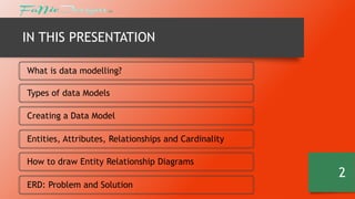
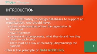
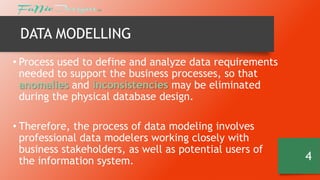
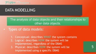
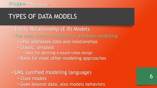


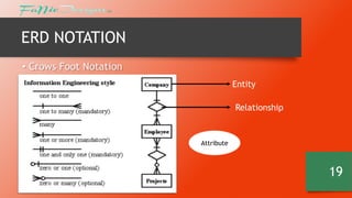
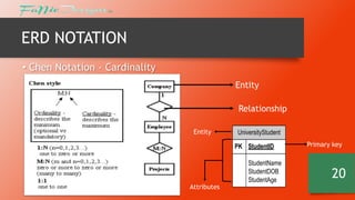
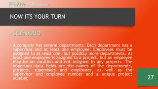
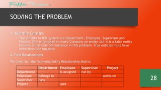

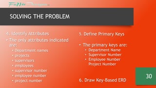
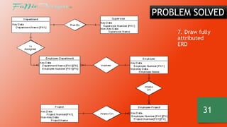
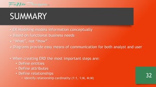

The document discusses data modeling and entity relationship diagrams. It defines data modeling as the process of defining and analyzing data requirements to support business processes. It describes the different types of data models including conceptual, logical, and physical models. It also explains the key components of entity relationship diagrams including entities, attributes, relationships, cardinality, and notation. The document provides an example of using an ERD to model a scenario involving departments, supervisors, employees, and projects.