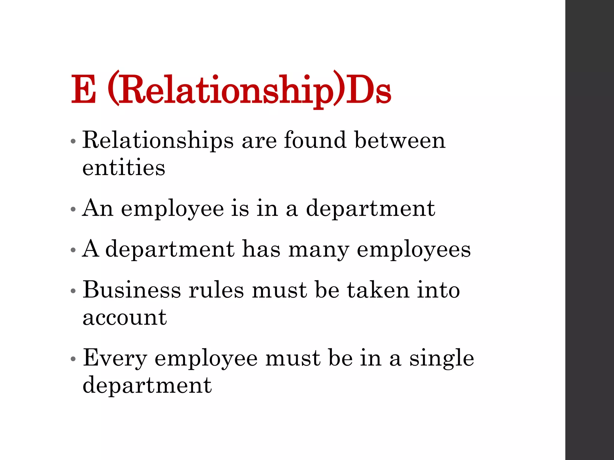
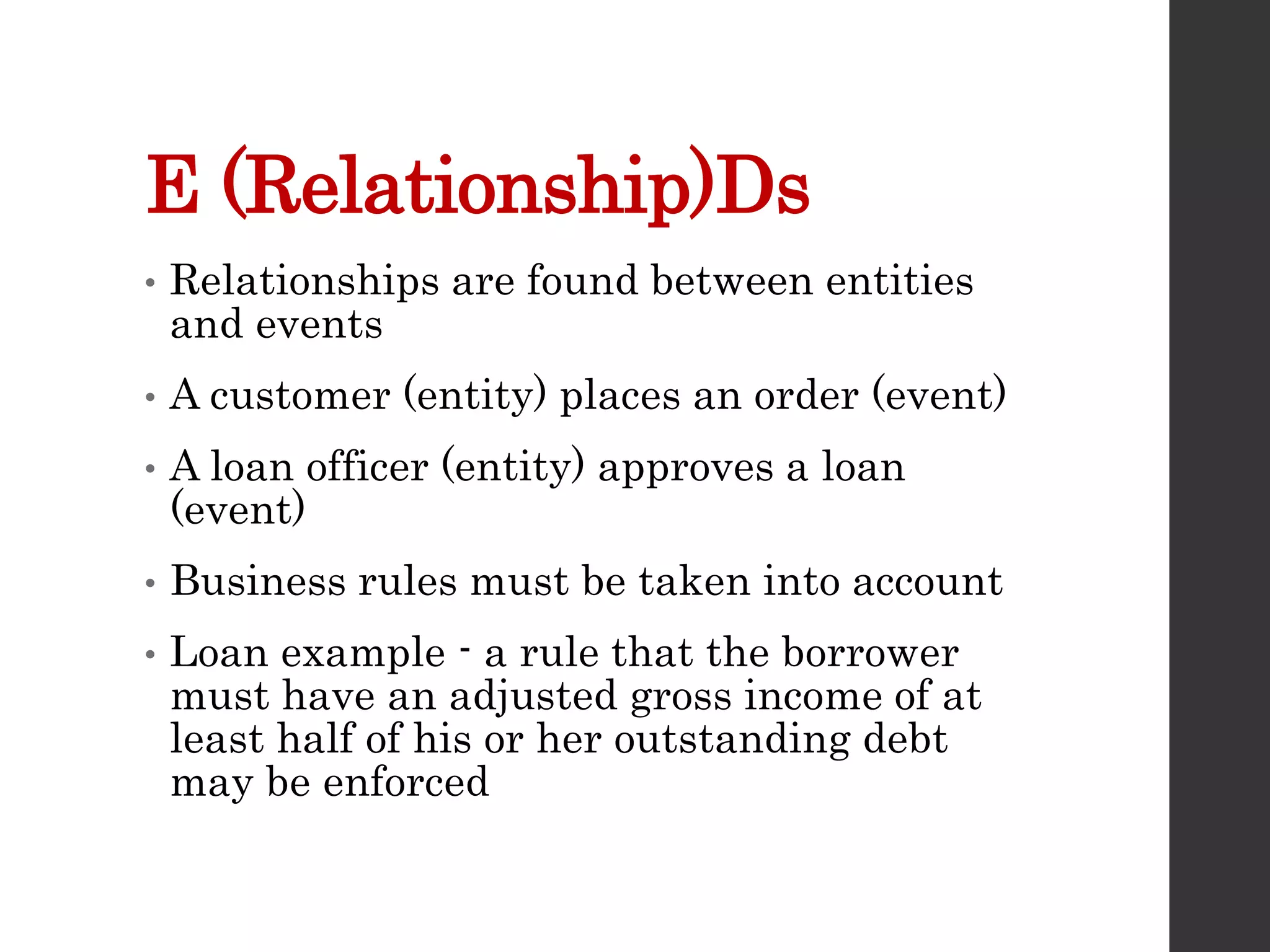
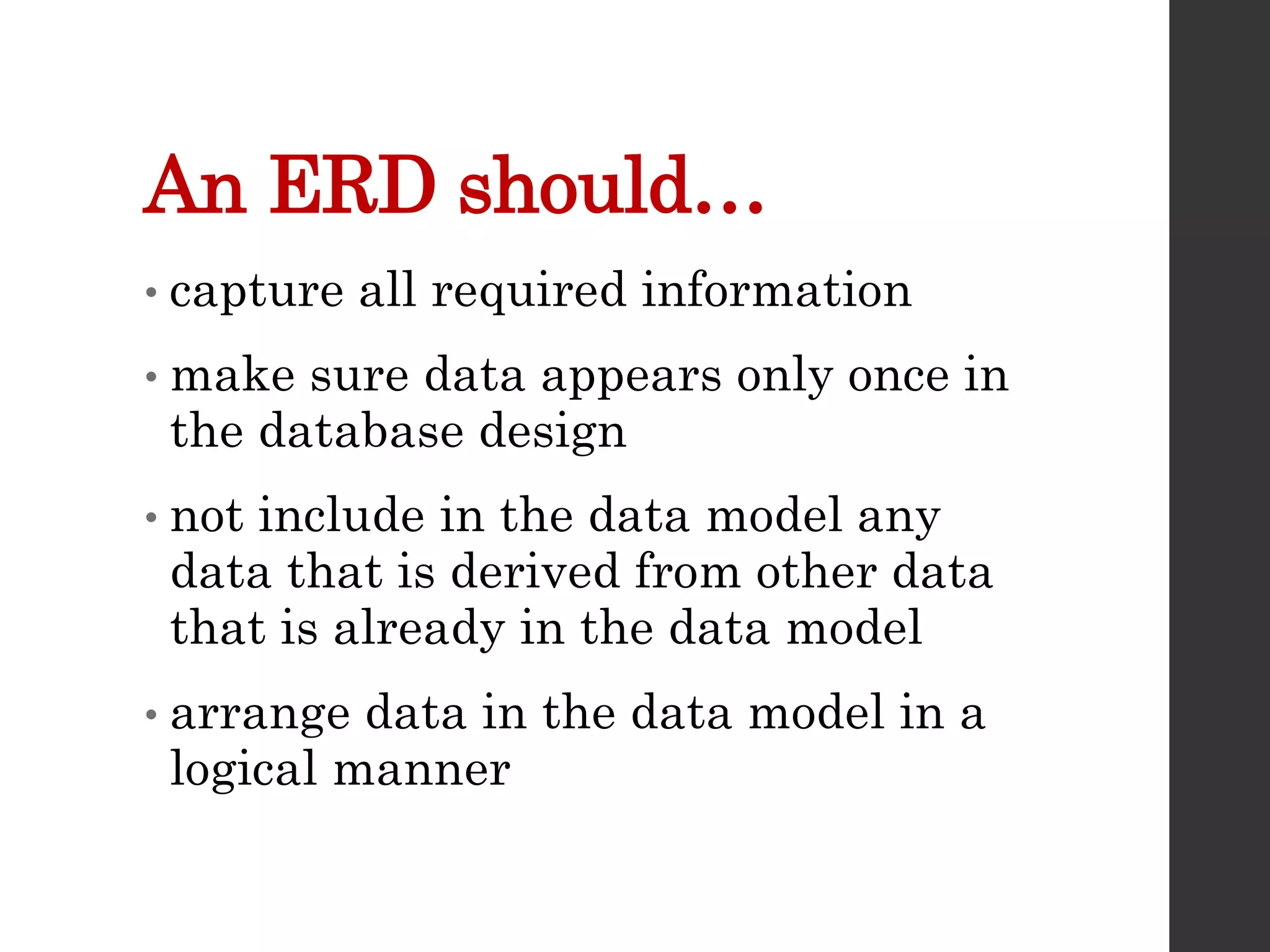
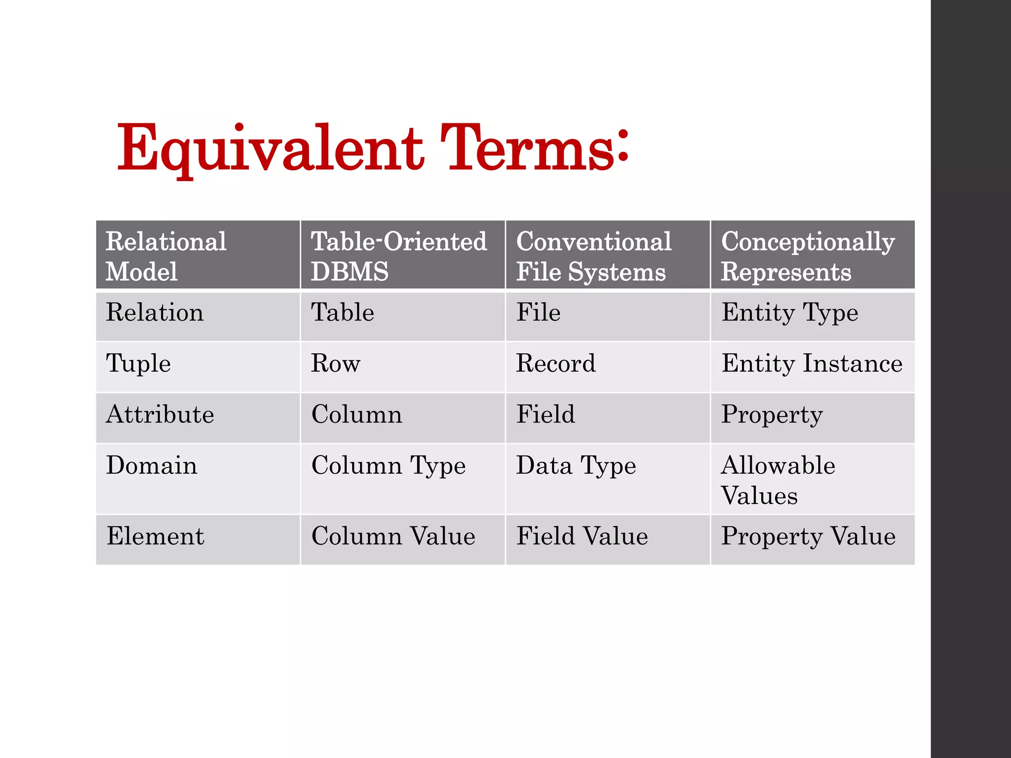
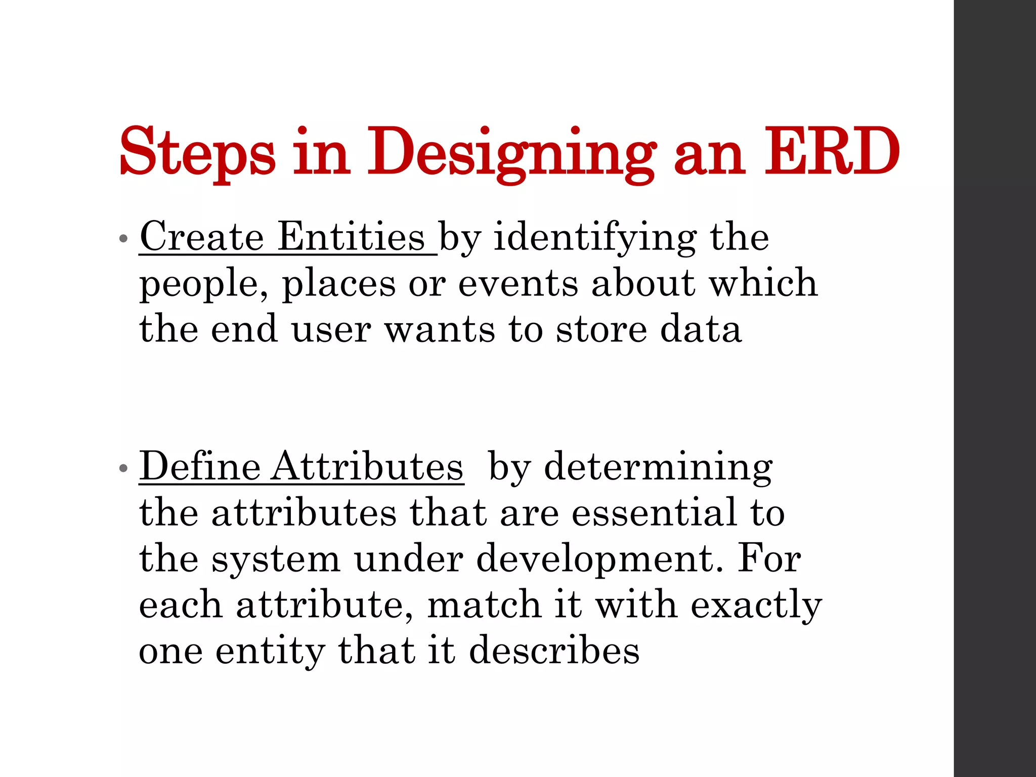
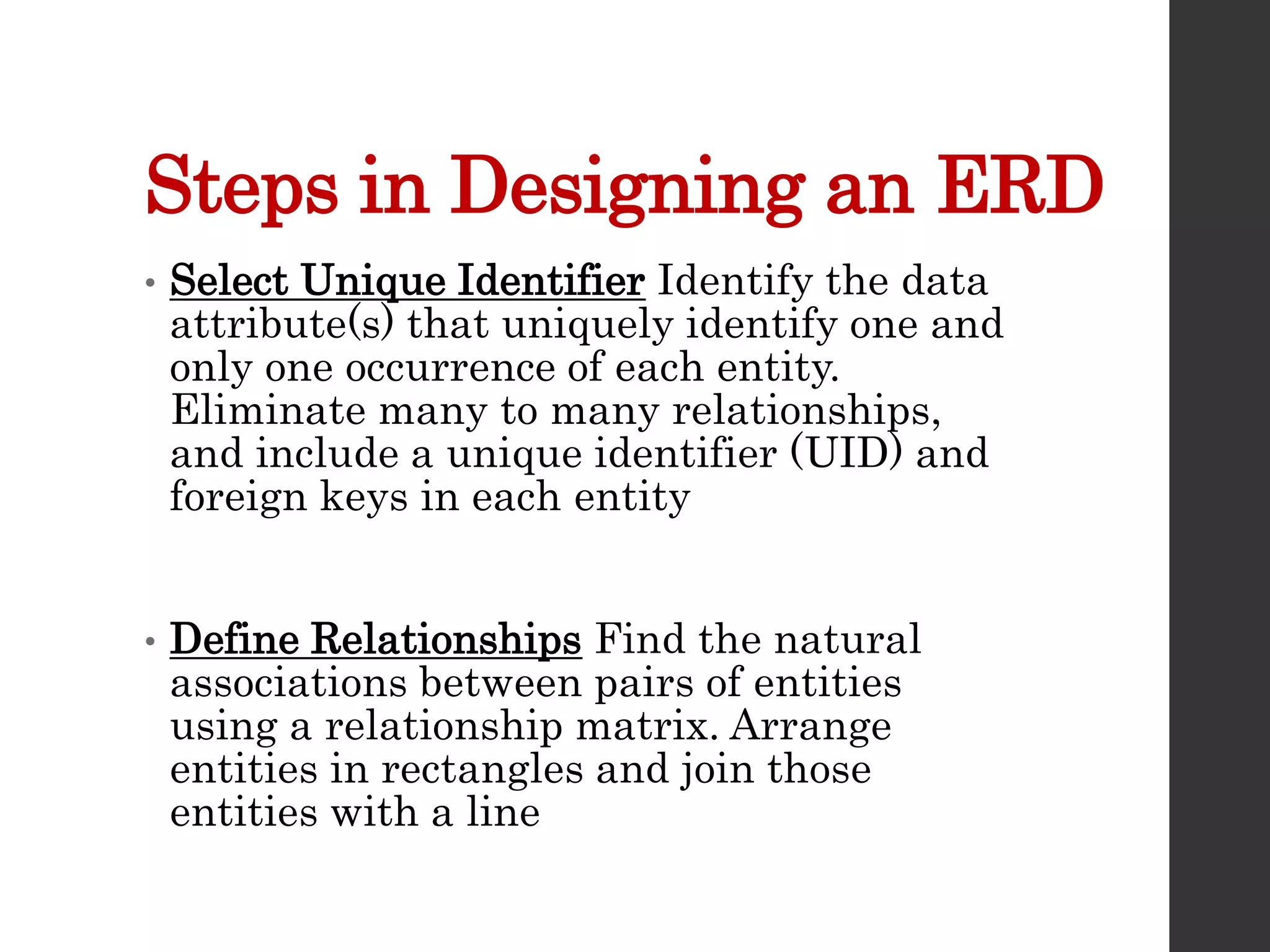
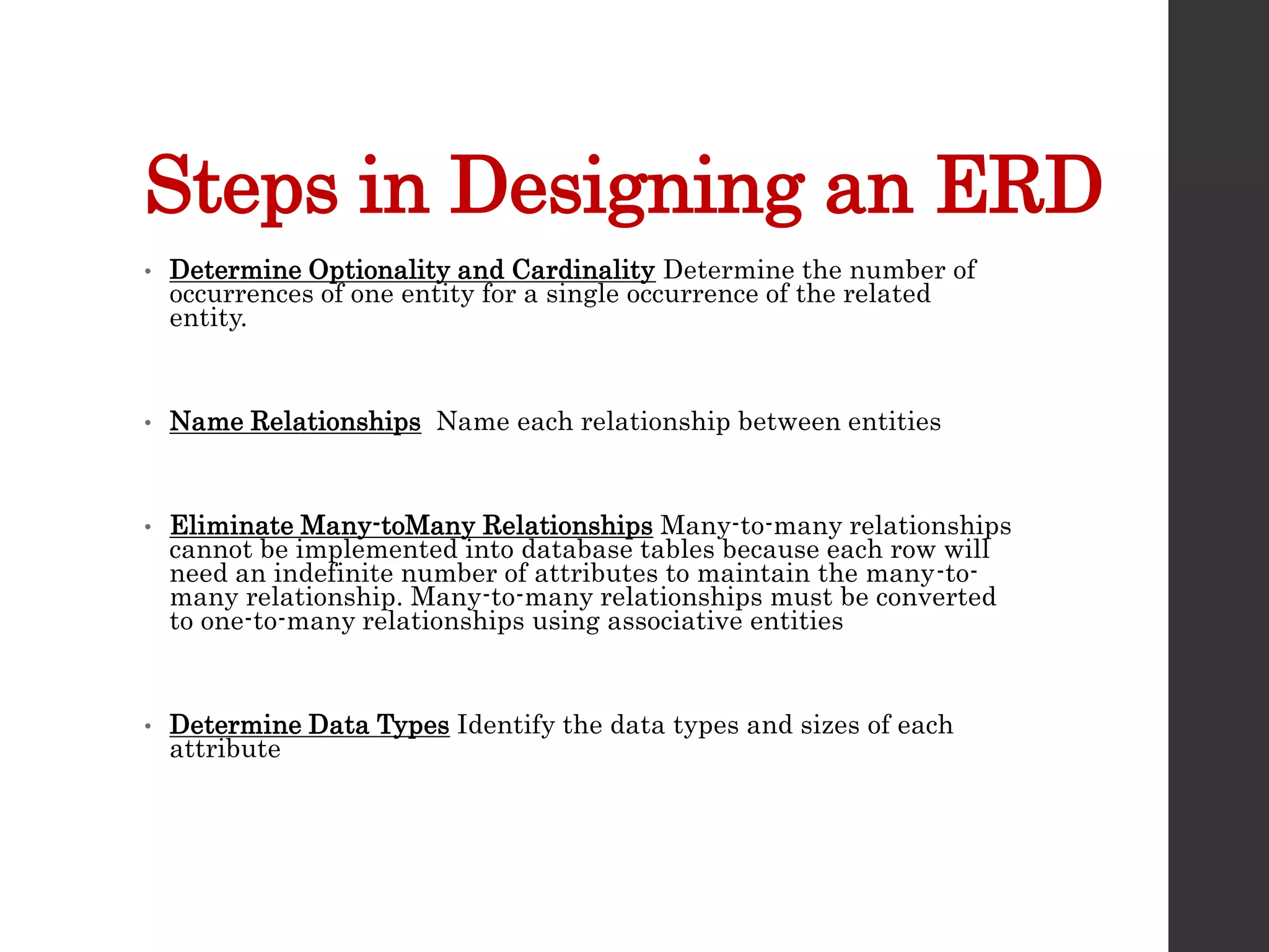
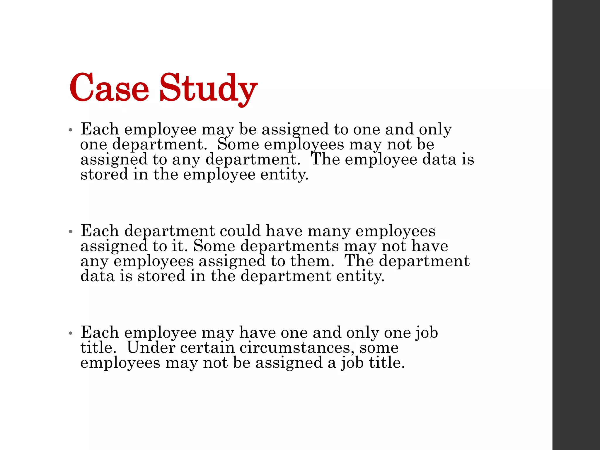
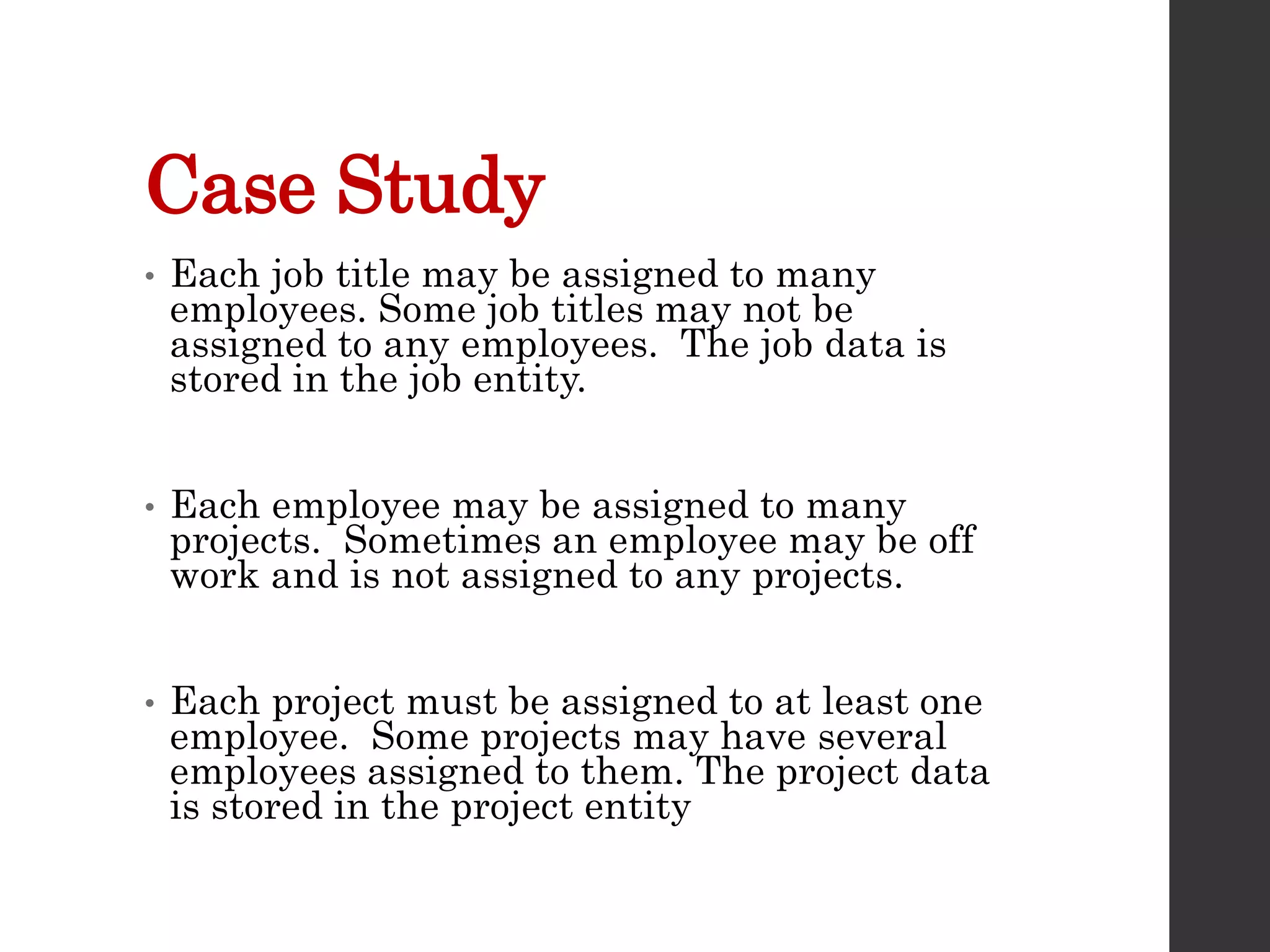
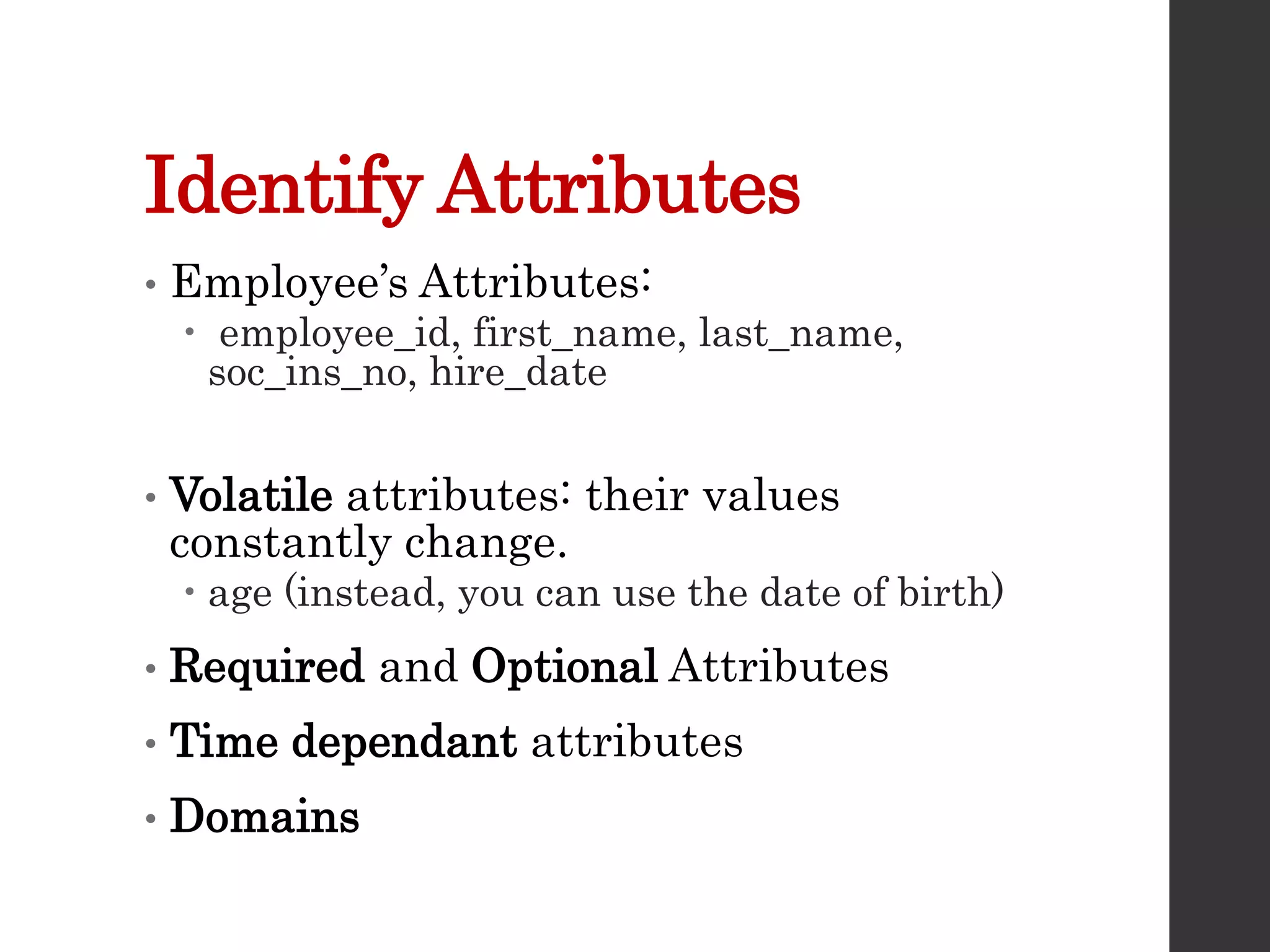
Entity Relationship
Diagrams
ERDs
Lecture 07
DBS211
What is an ERD?
• This conceptual data model
represents the data used in an
organization and the relationships
between the data
• It is a graphical representation of
the proposed database
Why ERDs?
• Documentation used to represent
the database in an abstract way
• The data model can be reviewed by
the end user and the person
responsible for the physical
database design
• Useful tool for the person creating
the data model.
Entities and Events
• Entities - People, places, things or
concepts about which information must
be recorded
• Entities as Events – Placing an order
or approving a loan
• Attributes for entities, events and
relationships would be things like
customer names or dates on which
orders were placed
• Attribute – one single valued fact
about an entity that we may want to
record
E (Relationship)Ds
• Relationships are found between
entities
• An employee is in a department
• A department has many employees
• Business rules must be taken into
account
• Every employee must be in a single
department
E (Relationship)Ds
• Relationships are found between entities
and events
• A customer (entity) places an order (event)
• A loan officer (entity) approves a loan
(event)
• Business rules must be taken into account
• Loan example - a rule that the borrower
must have an adjusted gross income of at
least half of his or her outstanding debt
may be enforced
An ERD should…
• capture all required information
• make sure data appears only once in
the database design
• not include in the data model any
data that is derived from other data
that is already in the data model
• arrange data in the data model in a
logical manner
Equivalent Terms:
Relational
Model
Table-Oriented
DBMS
Conventional
File Systems
Conceptionally
Represents
Relation Table File Entity Type
Tuple Row Record Entity Instance
Attribute Column Field Property
Domain Column Type Data Type Allowable
Values
Element Column Value Field Value Property Value
Customer
• Customer Relation
• Customer Table
• Customer File
• Customer Entity
Last Name
• Last name attribute in Customer
Relation
• Last name column in Customer
Table
• Last name field in Customer File
• Last name property of Customer
Entity
Phone Number
• Customer Relation phone number
domain is numeric or character
• Customer Table phone number
column type is numeric or character
• Customer File phone number data
type is numeric or character
• Customer Entity phone number
allowable values are numeric or
character
Phone Number is
4164915050
• Customer Relation phone number element
is 4164915050 or (416) 491-5050
• Customer Table phone number column
value is 4164915050 or (416) 491-5050
• Customer Table phone number field value
is 4164915050 or (416) 491-5050
• Customer Table phone number property
value is 4164915050 or (416) 491-5050
• A numeric field can used an edit code to
get the special characters included “() – ”
Last Name, First Name,
Phone
• Smith, Bill, 9056668888 as a tuple
in the Customer Relation
• Smith, Bill, 9056668888 as a row in
the Customer Table
• Smith, Bill, 9056668888 as a record
in the Customer File
• Smith, Bill, 9056668888 as an entity
instance of the Customer Entity
Steps in Designing an ERD
• Create Entities by identifying the
people, places or events about which
the end user wants to store data
• Define Attributes by determining
the attributes that are essential to
the system under development. For
each attribute, match it with exactly
one entity that it describes
Steps in Designing an ERD
• Select Unique Identifier Identify the data
attribute(s) that uniquely identify one and
only one occurrence of each entity.
Eliminate many to many relationships,
and include a unique identifier (UID) and
foreign keys in each entity
• Define Relationships Find the natural
associations between pairs of entities
using a relationship matrix. Arrange
entities in rectangles and join those
entities with a line
Steps in Designing an ERD
• Determine Optionality and Cardinality Determine the number of
occurrences of one entity for a single occurrence of the related
entity.
• Name Relationships Name each relationship between entities
• Eliminate Many-toMany Relationships Many-to-many relationships
cannot be implemented into database tables because each row will
need an indefinite number of attributes to maintain the many-to-
many relationship. Many-to-many relationships must be converted
to one-to-many relationships using associative entities
• Determine Data Types Identify the data types and sizes of each
attribute
Case Study
• Each employee may be assigned to one and only
one department. Some employees may not be
assigned to any department. The employee data is
stored in the employee entity.
• Each department could have many employees
assigned to it. Some departments may not have
any employees assigned to them. The department
data is stored in the department entity.
• Each employee may have one and only one job
title. Under certain circumstances, some
employees may not be assigned a job title.
Case Study
• Each job title may be assigned to many
employees. Some job titles may not be
assigned to any employees. The job data is
stored in the job entity.
• Each employee may be assigned to many
projects. Sometimes an employee may be off
work and is not assigned to any projects.
• Each project must be assigned to at least one
employee. Some projects may have several
employees assigned to them. The project data
is stored in the project entity
Case Study
• Entities:
 Employee
 Department
 Job
 Project
Identify Attributes
• Employee’s Attributes:
 employee_id, first_name, last_name,
soc_ins_no, hire_date
• Volatile attributes: their values
constantly change.
 age (instead, you can use the date of birth)
• Required and Optional Attributes
• Time dependant attributes
• Domains
Select Unique Identifier
(UID)
• Every entity must have unique
identifying attribute(s) called a unique
identifier
• This is a single attribute or a collection
of attributes that uniquely identifies
one and only one instance of an entity.
• When two or more attributes are used
as the unique identifier it is called a
concatenated key.
Candidate Key
• Sometimes there are several attributes
that could be the unique identifier
• For an EMPLOYEE entity we could
use
 employee_id
 social_ins_no
 email_address
 telephone_no
• These are all called candidate keys
Candidate Keys Must:
• Be unique for each instance within
an entity
• Never be missing, incomplete or
NULL for an instance
• Use no attributes other than those
necessary to uniquely identify an
instance of an entity
Unique Identifier
• Should be meaningless other than as
an identifier
• Should never change
• Should not have a limited number of
values available
• Only one (UID) should be specified for
each table
EMPLOYEE EXAMPLE
• Soc_ins_no is not meaningless
 Do you want people knowing your
personal number in the company?
• A telephone number may change
• The best choice is an arbitrarily
generated employee number
assigned when the employee is hired
Determining relationships
DEPARTMENT EMPLOYEE
A relationship is like a verb that shows some dependency or
natural association between two entities
A department contains employees
An employee is assigned to a department
Determining optionality and
cardinality
TABLE A TABLE B
Each instance of Table B is related to a maximum of
one and a minimum of one instance of Table A
Optionality and Cardinality
• Each instance of Table A is related to zero,
one or more instances of Table B
TABLE A TABLE B
Optionality and Cardinality
One and only
one
One or more
Zero or one Zero or many
Cardinality Notations
• Different notations are used to
represent the cardinality of
relationships
 1:1
 1:M
 M:M
1:M
• No information on optionality is
given with this 1:M example
PK employee_id
first_name
last_name
soc_sec_no
hire_date
job_id
FK1 department_code
PK department_code
department_name
manager_id
DEPARTMENT
EMPLOYEE
M
1
Summary
• Entity or Event
• Relationship
• Optionality
• Cardinality
• Attributes
• UID
• ERD Diagrams

Lecture7.pptx

  • 1.
  • 2.
    What is anERD? • This conceptual data model represents the data used in an organization and the relationships between the data • It is a graphical representation of the proposed database
  • 3.
    Why ERDs? • Documentationused to represent the database in an abstract way • The data model can be reviewed by the end user and the person responsible for the physical database design • Useful tool for the person creating the data model.
  • 4.
    Entities and Events •Entities - People, places, things or concepts about which information must be recorded • Entities as Events – Placing an order or approving a loan • Attributes for entities, events and relationships would be things like customer names or dates on which orders were placed • Attribute – one single valued fact about an entity that we may want to record
  • 5.
    E (Relationship)Ds • Relationshipsare found between entities • An employee is in a department • A department has many employees • Business rules must be taken into account • Every employee must be in a single department
  • 6.
    E (Relationship)Ds • Relationshipsare found between entities and events • A customer (entity) places an order (event) • A loan officer (entity) approves a loan (event) • Business rules must be taken into account • Loan example - a rule that the borrower must have an adjusted gross income of at least half of his or her outstanding debt may be enforced
  • 7.
    An ERD should… •capture all required information • make sure data appears only once in the database design • not include in the data model any data that is derived from other data that is already in the data model • arrange data in the data model in a logical manner
  • 8.
    Equivalent Terms: Relational Model Table-Oriented DBMS Conventional File Systems Conceptionally Represents RelationTable File Entity Type Tuple Row Record Entity Instance Attribute Column Field Property Domain Column Type Data Type Allowable Values Element Column Value Field Value Property Value
  • 9.
    Customer • Customer Relation •Customer Table • Customer File • Customer Entity
  • 10.
    Last Name • Lastname attribute in Customer Relation • Last name column in Customer Table • Last name field in Customer File • Last name property of Customer Entity
  • 11.
    Phone Number • CustomerRelation phone number domain is numeric or character • Customer Table phone number column type is numeric or character • Customer File phone number data type is numeric or character • Customer Entity phone number allowable values are numeric or character
  • 12.
    Phone Number is 4164915050 •Customer Relation phone number element is 4164915050 or (416) 491-5050 • Customer Table phone number column value is 4164915050 or (416) 491-5050 • Customer Table phone number field value is 4164915050 or (416) 491-5050 • Customer Table phone number property value is 4164915050 or (416) 491-5050 • A numeric field can used an edit code to get the special characters included “() – ”
  • 13.
    Last Name, FirstName, Phone • Smith, Bill, 9056668888 as a tuple in the Customer Relation • Smith, Bill, 9056668888 as a row in the Customer Table • Smith, Bill, 9056668888 as a record in the Customer File • Smith, Bill, 9056668888 as an entity instance of the Customer Entity
  • 14.
    Steps in Designingan ERD • Create Entities by identifying the people, places or events about which the end user wants to store data • Define Attributes by determining the attributes that are essential to the system under development. For each attribute, match it with exactly one entity that it describes
  • 15.
    Steps in Designingan ERD • Select Unique Identifier Identify the data attribute(s) that uniquely identify one and only one occurrence of each entity. Eliminate many to many relationships, and include a unique identifier (UID) and foreign keys in each entity • Define Relationships Find the natural associations between pairs of entities using a relationship matrix. Arrange entities in rectangles and join those entities with a line
  • 16.
    Steps in Designingan ERD • Determine Optionality and Cardinality Determine the number of occurrences of one entity for a single occurrence of the related entity. • Name Relationships Name each relationship between entities • Eliminate Many-toMany Relationships Many-to-many relationships cannot be implemented into database tables because each row will need an indefinite number of attributes to maintain the many-to- many relationship. Many-to-many relationships must be converted to one-to-many relationships using associative entities • Determine Data Types Identify the data types and sizes of each attribute
  • 17.
    Case Study • Eachemployee may be assigned to one and only one department. Some employees may not be assigned to any department. The employee data is stored in the employee entity. • Each department could have many employees assigned to it. Some departments may not have any employees assigned to them. The department data is stored in the department entity. • Each employee may have one and only one job title. Under certain circumstances, some employees may not be assigned a job title.
  • 18.
    Case Study • Eachjob title may be assigned to many employees. Some job titles may not be assigned to any employees. The job data is stored in the job entity. • Each employee may be assigned to many projects. Sometimes an employee may be off work and is not assigned to any projects. • Each project must be assigned to at least one employee. Some projects may have several employees assigned to them. The project data is stored in the project entity
  • 19.
    Case Study • Entities: Employee  Department  Job  Project
  • 20.
    Identify Attributes • Employee’sAttributes:  employee_id, first_name, last_name, soc_ins_no, hire_date • Volatile attributes: their values constantly change.  age (instead, you can use the date of birth) • Required and Optional Attributes • Time dependant attributes • Domains
  • 21.
    Select Unique Identifier (UID) •Every entity must have unique identifying attribute(s) called a unique identifier • This is a single attribute or a collection of attributes that uniquely identifies one and only one instance of an entity. • When two or more attributes are used as the unique identifier it is called a concatenated key.
  • 22.
    Candidate Key • Sometimesthere are several attributes that could be the unique identifier • For an EMPLOYEE entity we could use  employee_id  social_ins_no  email_address  telephone_no • These are all called candidate keys
  • 23.
    Candidate Keys Must: •Be unique for each instance within an entity • Never be missing, incomplete or NULL for an instance • Use no attributes other than those necessary to uniquely identify an instance of an entity
  • 24.
    Unique Identifier • Shouldbe meaningless other than as an identifier • Should never change • Should not have a limited number of values available • Only one (UID) should be specified for each table
  • 25.
    EMPLOYEE EXAMPLE • Soc_ins_nois not meaningless  Do you want people knowing your personal number in the company? • A telephone number may change • The best choice is an arbitrarily generated employee number assigned when the employee is hired
  • 26.
    Determining relationships DEPARTMENT EMPLOYEE Arelationship is like a verb that shows some dependency or natural association between two entities A department contains employees An employee is assigned to a department
  • 27.
    Determining optionality and cardinality TABLEA TABLE B Each instance of Table B is related to a maximum of one and a minimum of one instance of Table A
  • 28.
    Optionality and Cardinality •Each instance of Table A is related to zero, one or more instances of Table B TABLE A TABLE B
  • 29.
    Optionality and Cardinality Oneand only one One or more Zero or one Zero or many
  • 30.
    Cardinality Notations • Differentnotations are used to represent the cardinality of relationships  1:1  1:M  M:M
  • 31.
    1:M • No informationon optionality is given with this 1:M example PK employee_id first_name last_name soc_sec_no hire_date job_id FK1 department_code PK department_code department_name manager_id DEPARTMENT EMPLOYEE M 1
  • 32.
    Summary • Entity orEvent • Relationship • Optionality • Cardinality • Attributes • UID • ERD Diagrams