Download as PDF, PPTX
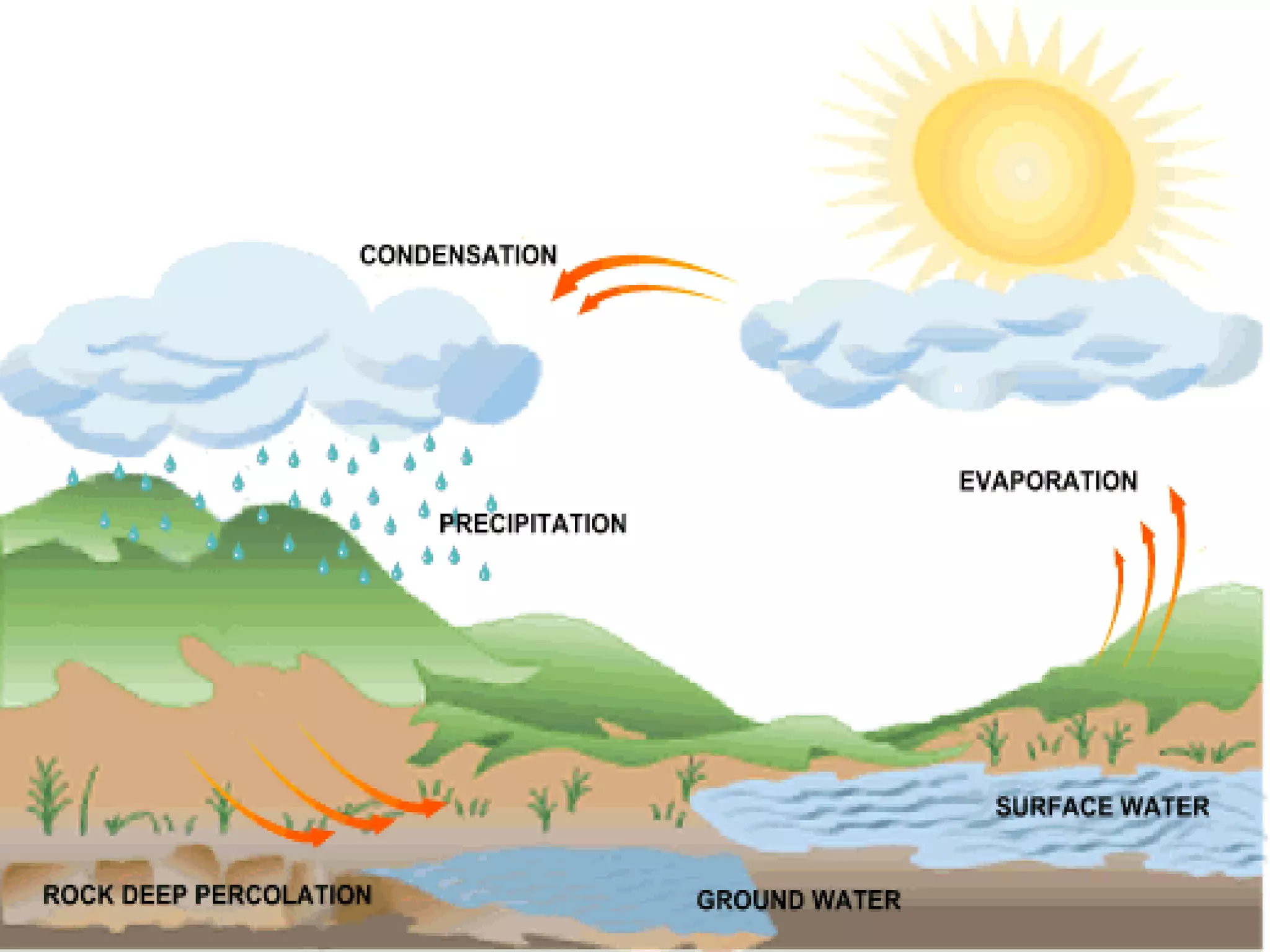
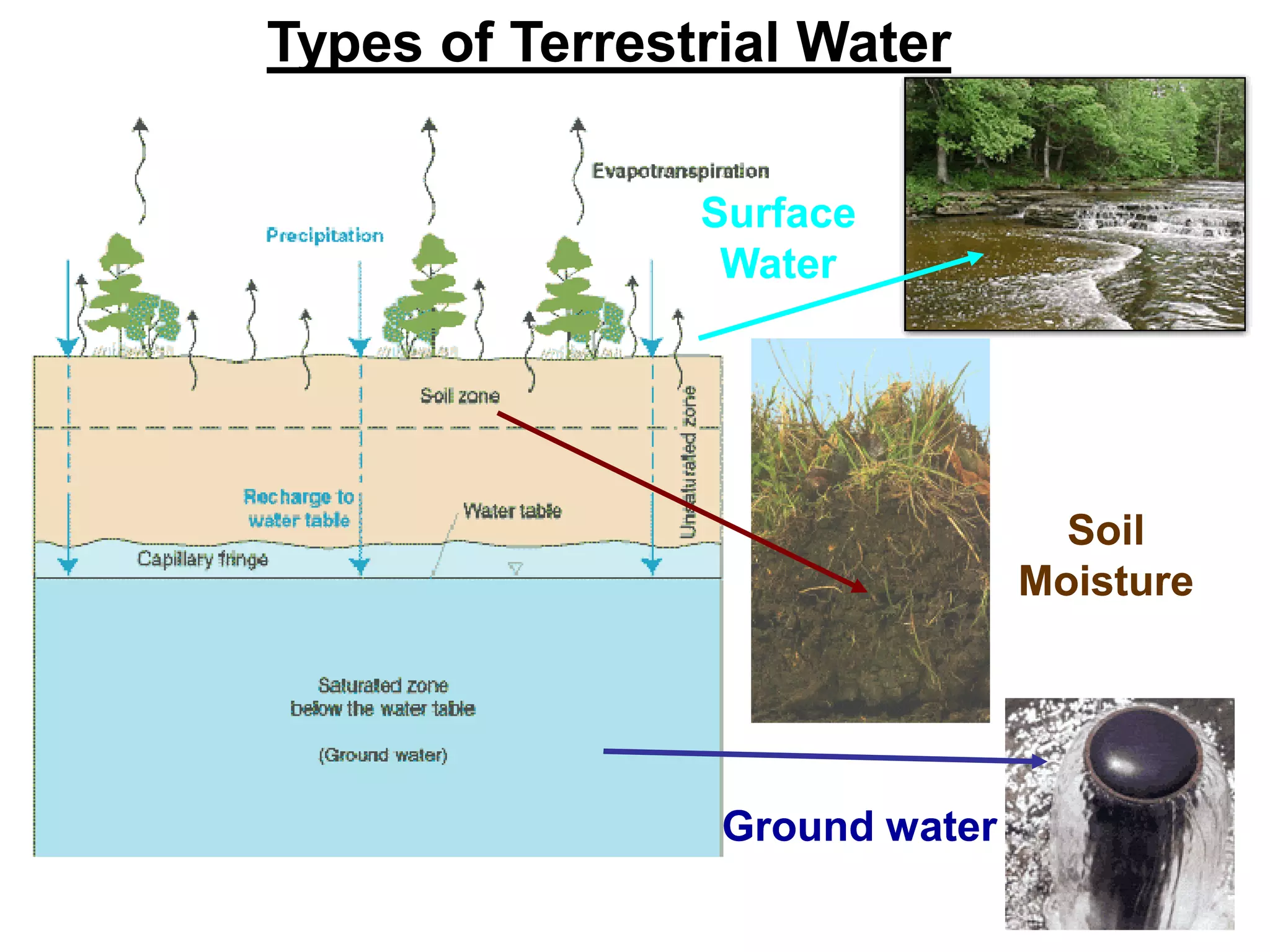
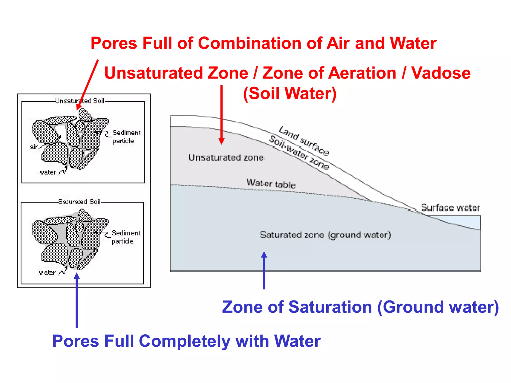
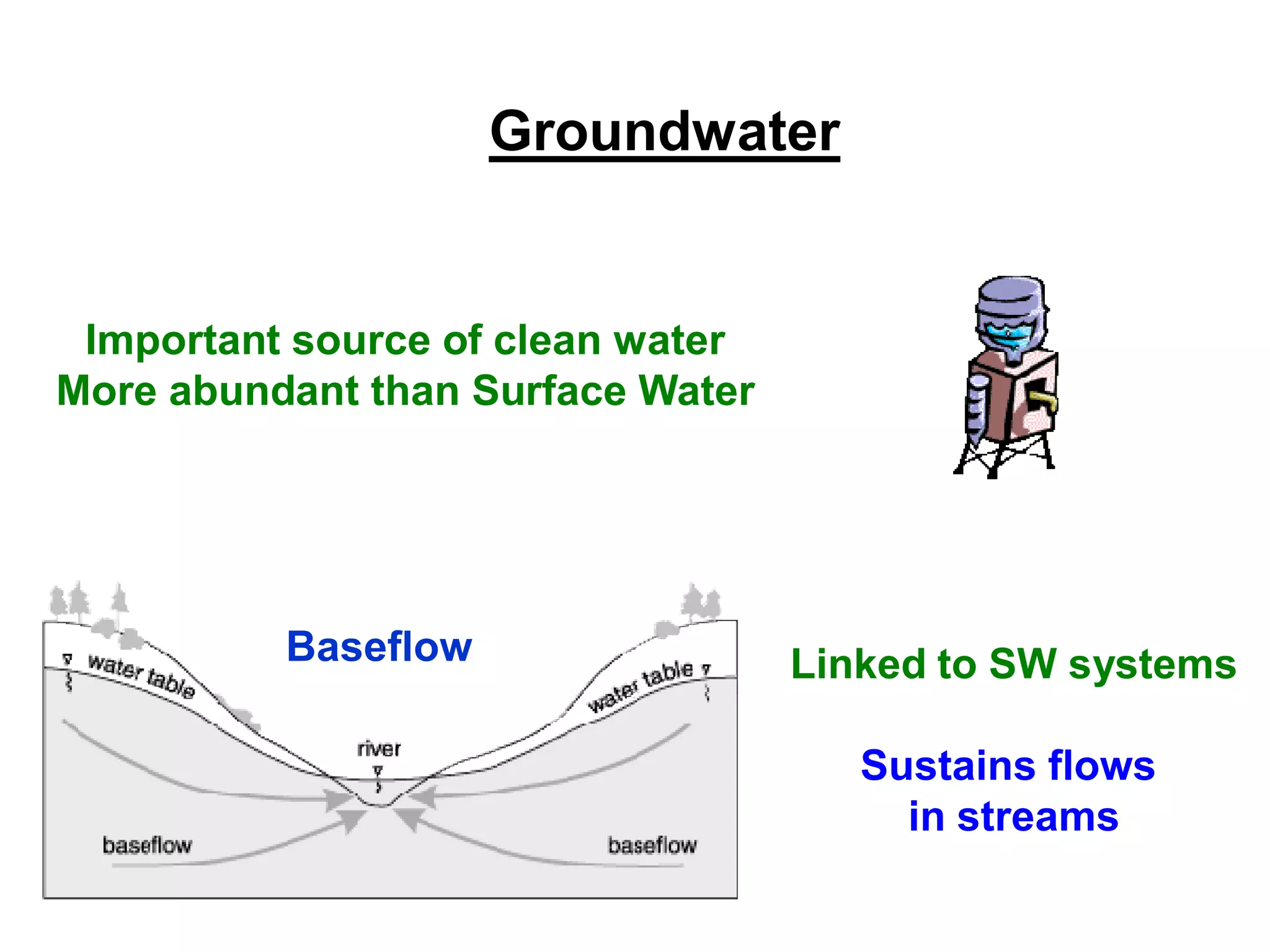

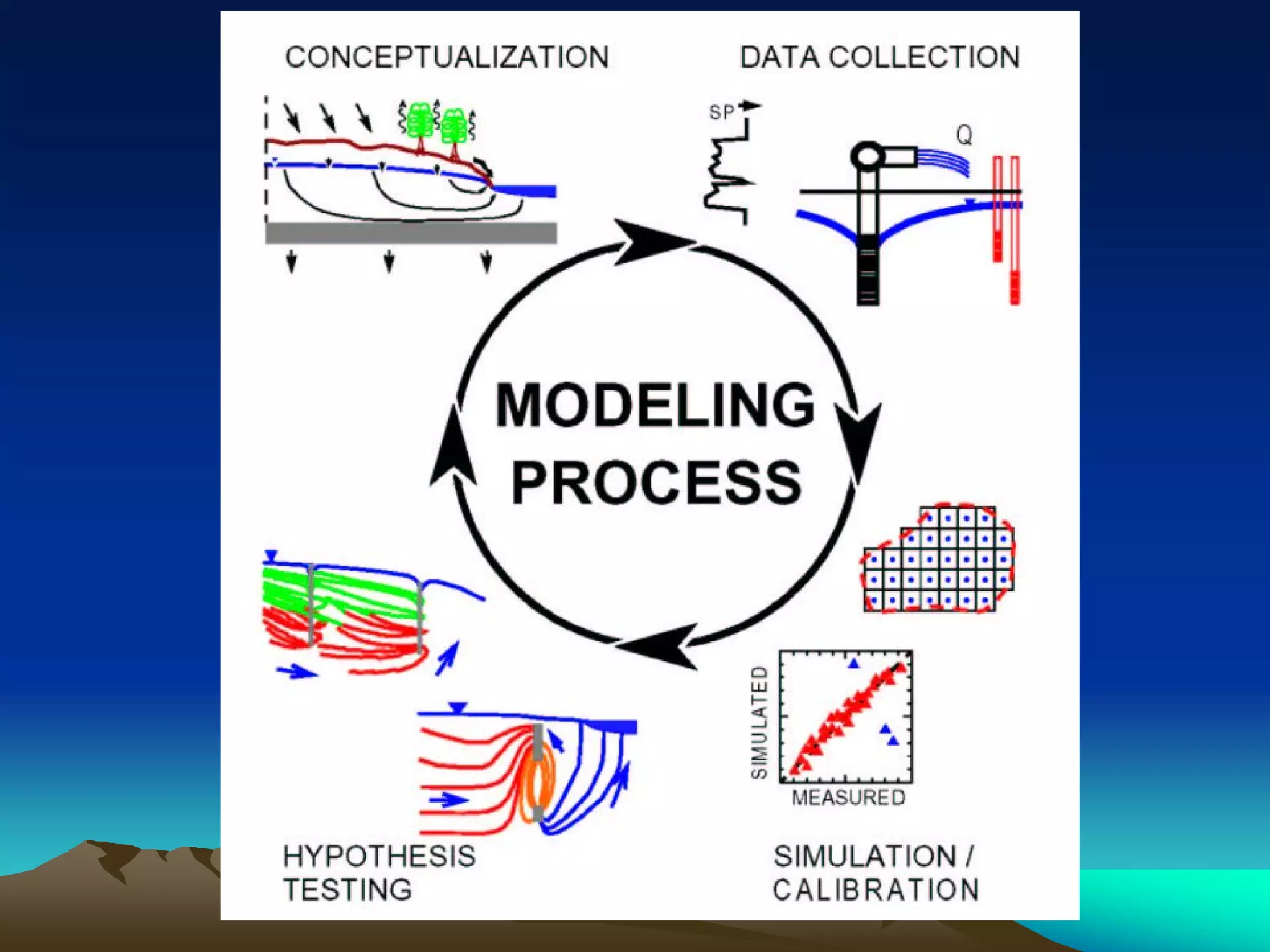
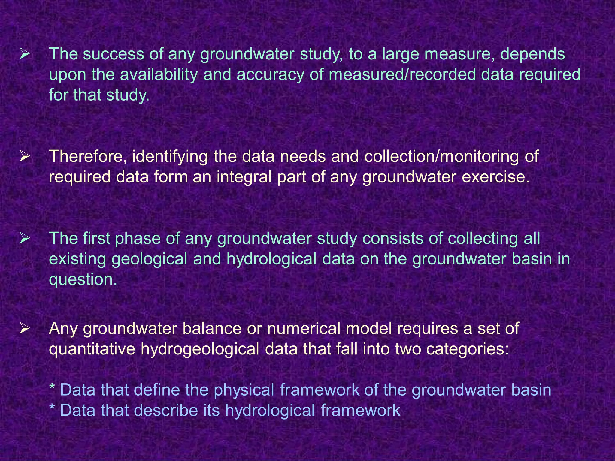
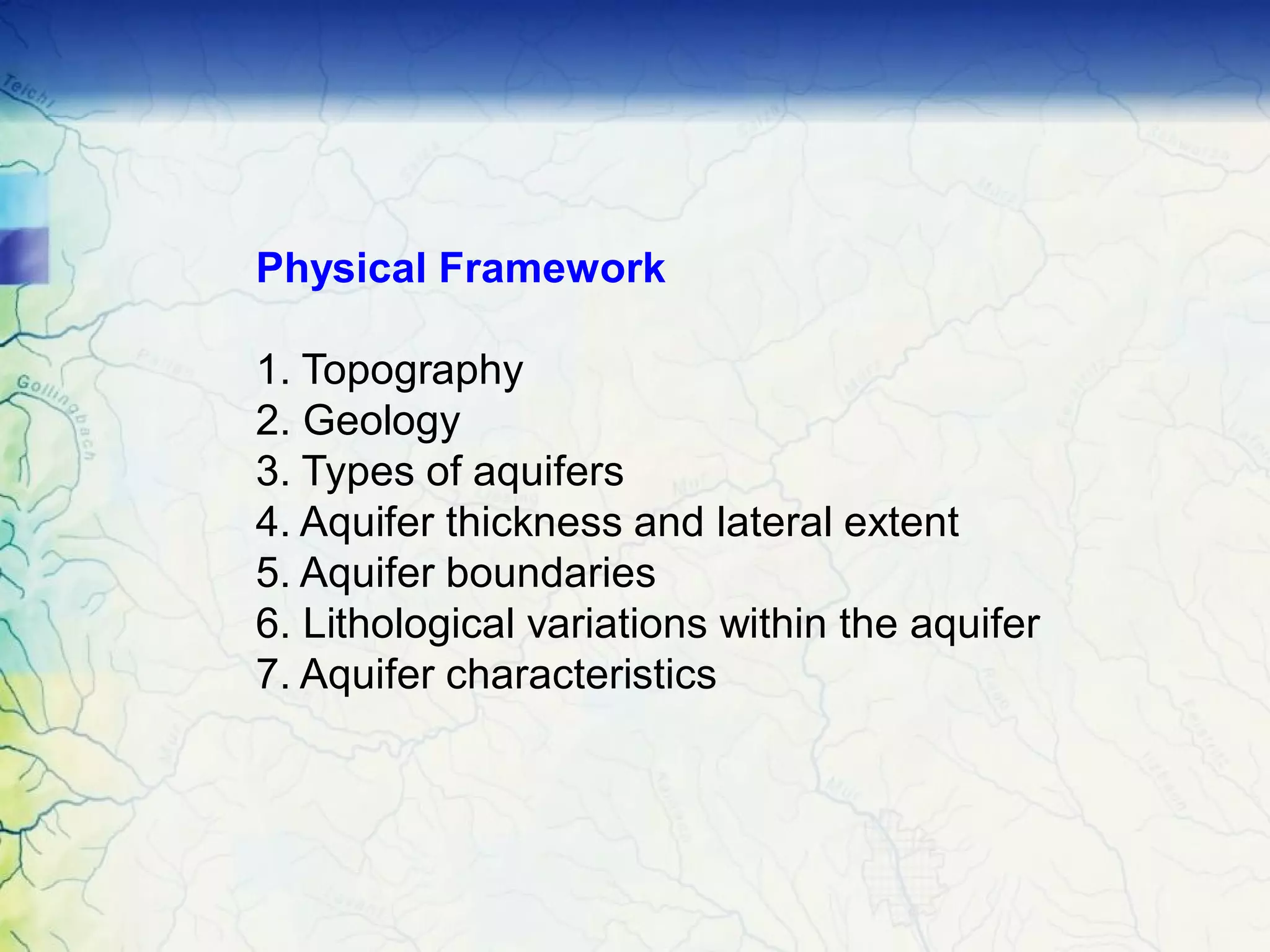
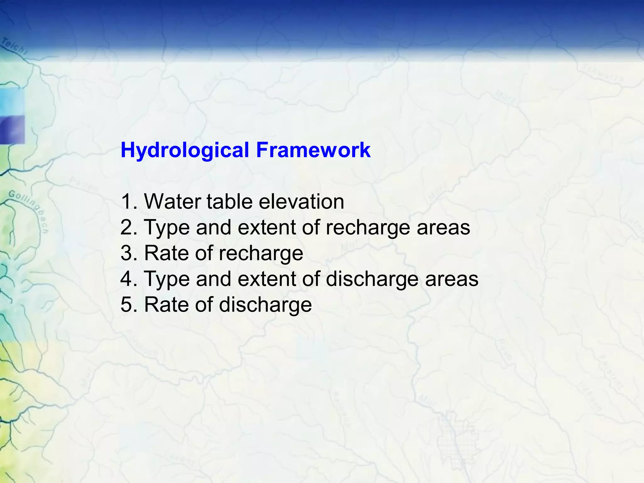
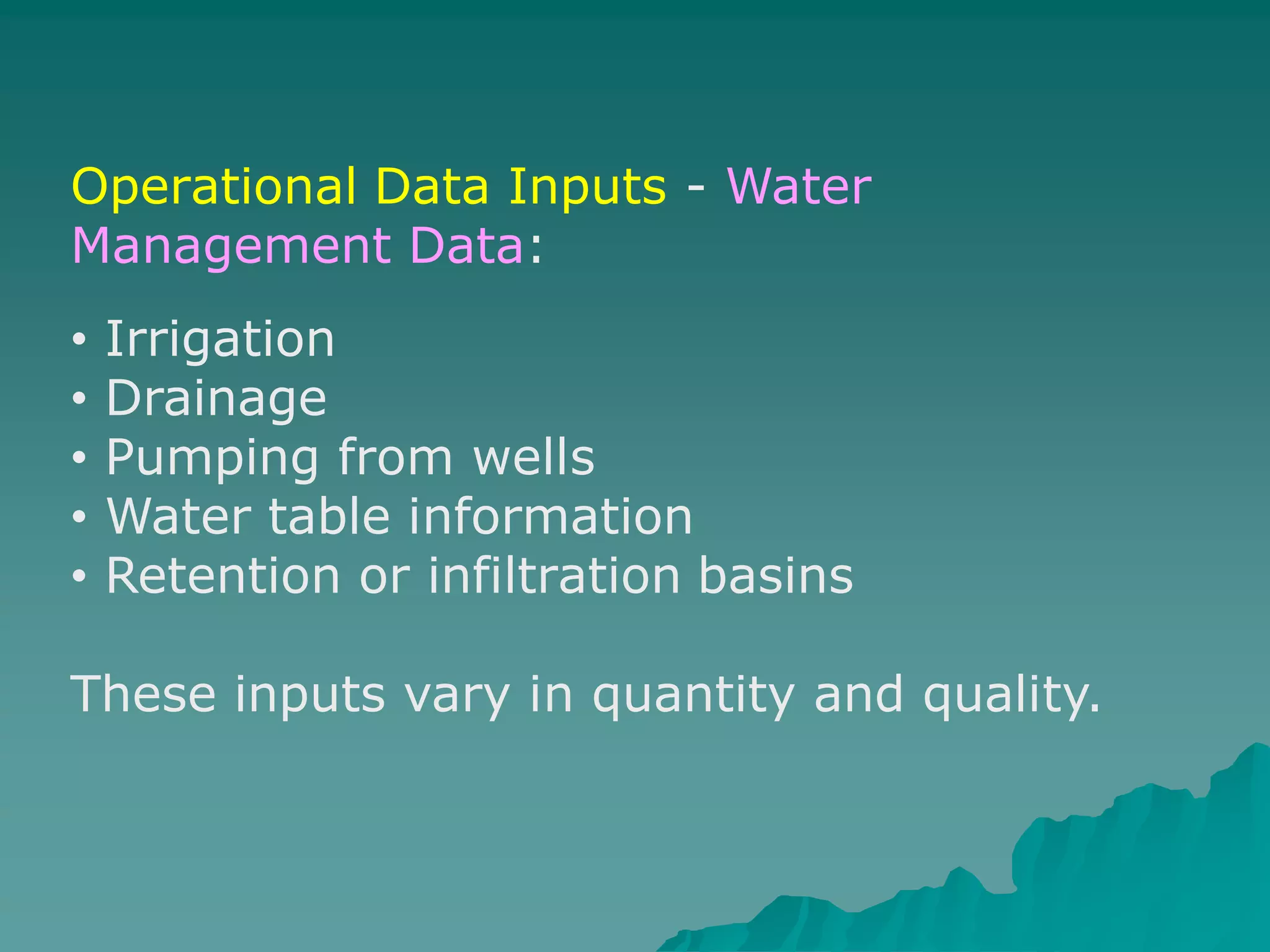
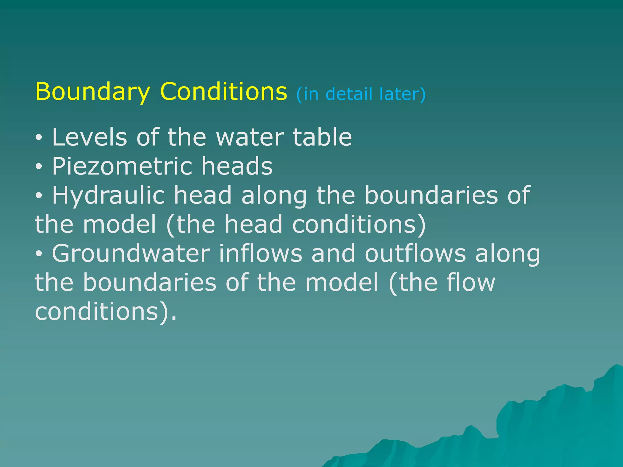
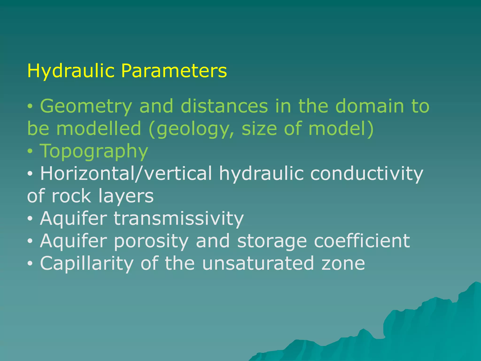
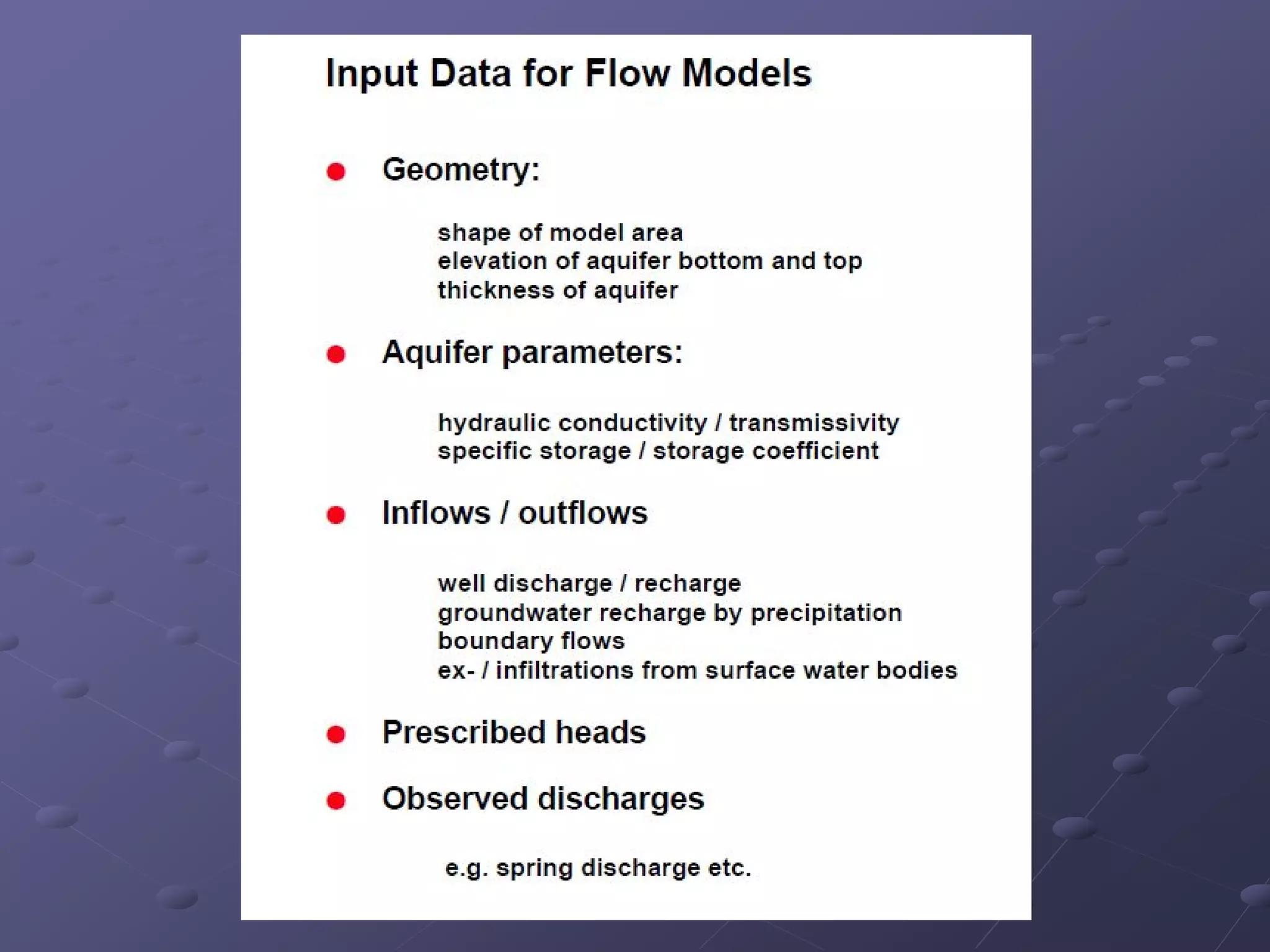

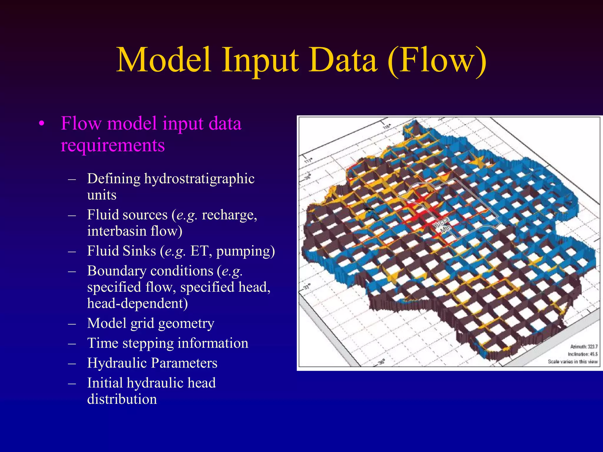
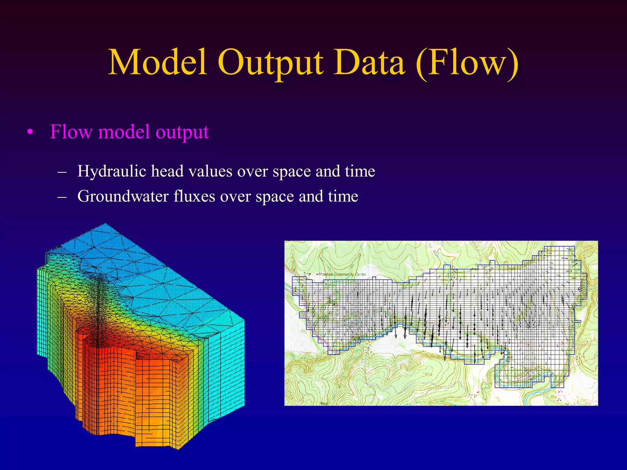
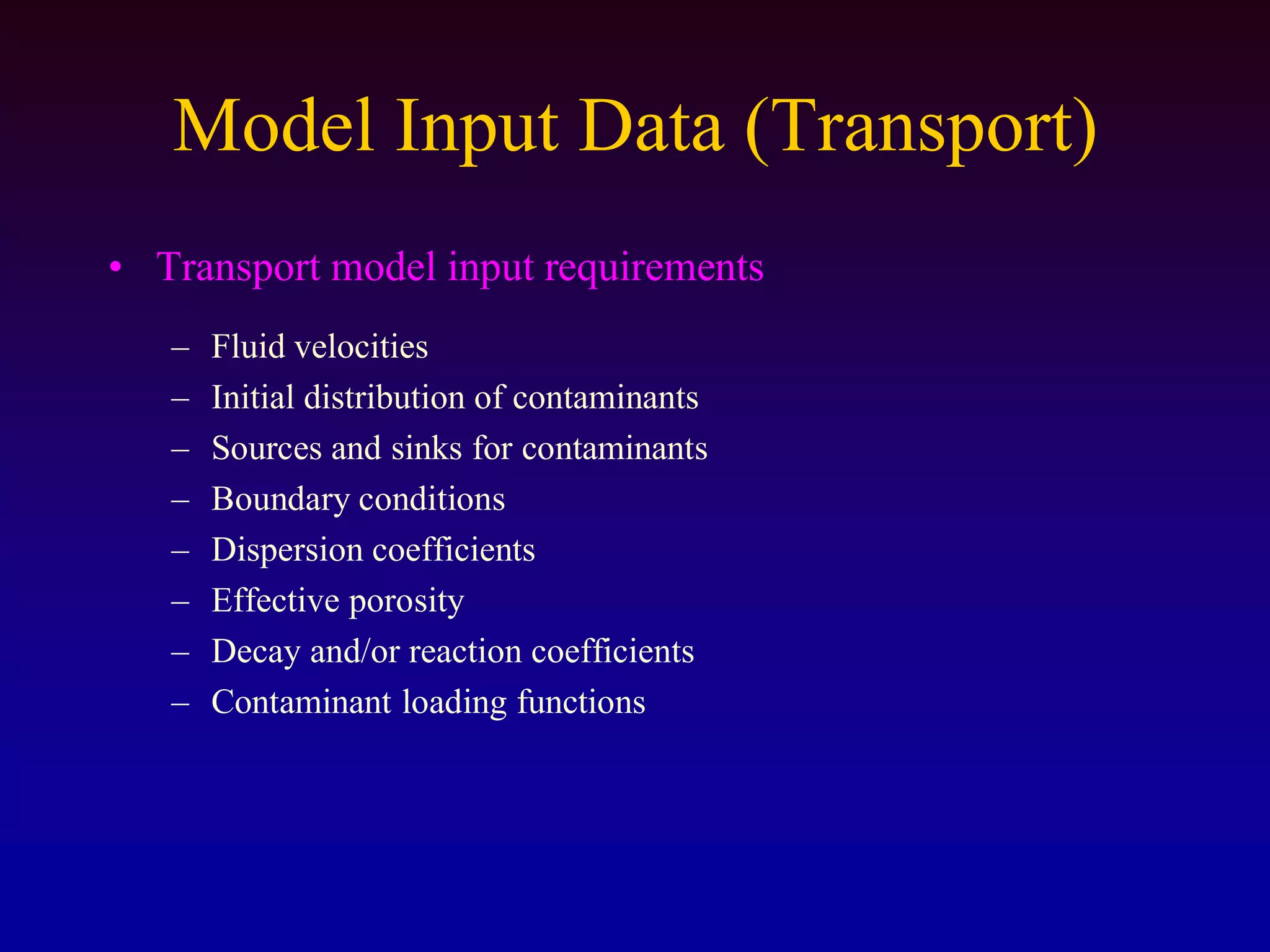
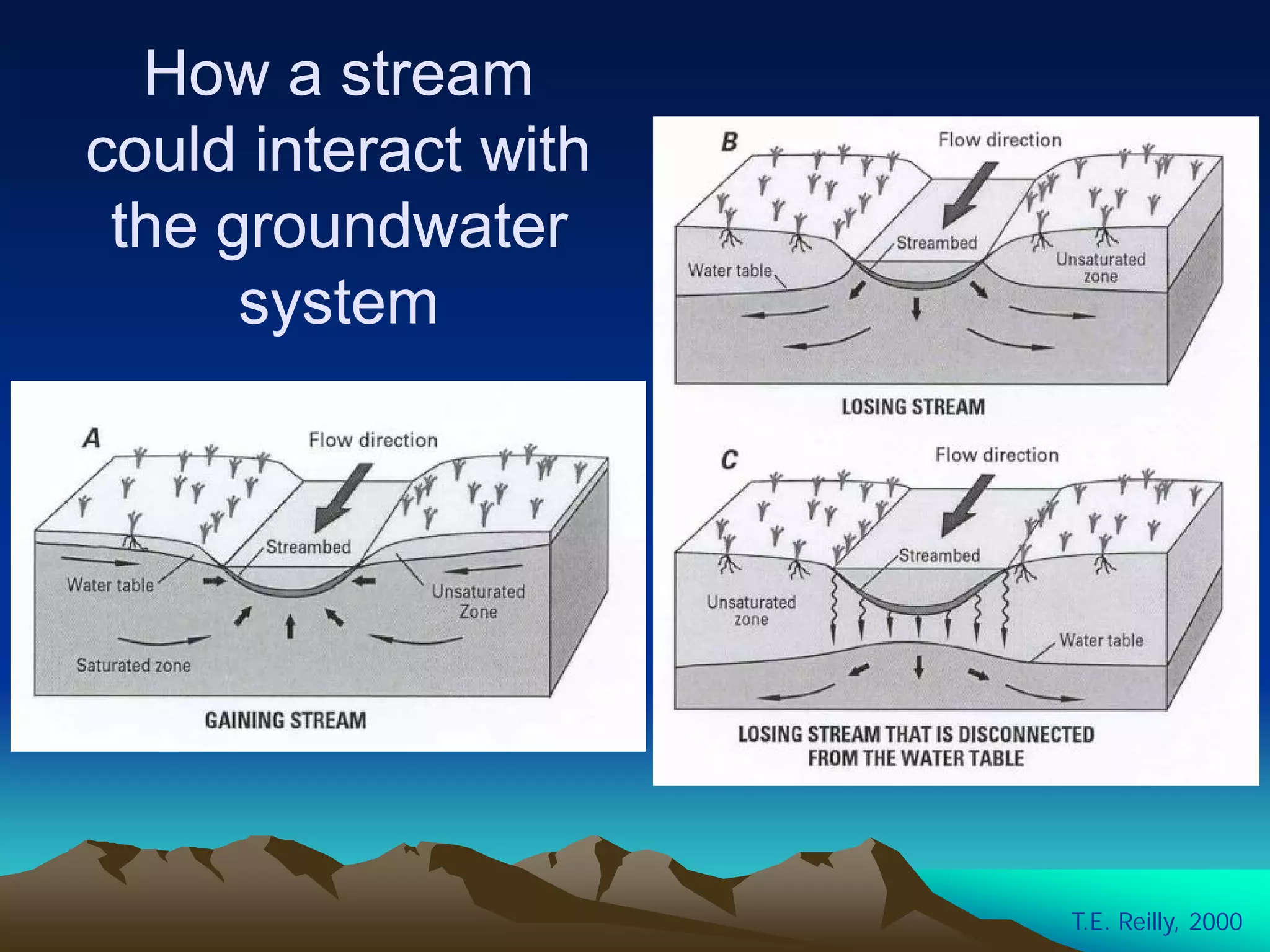
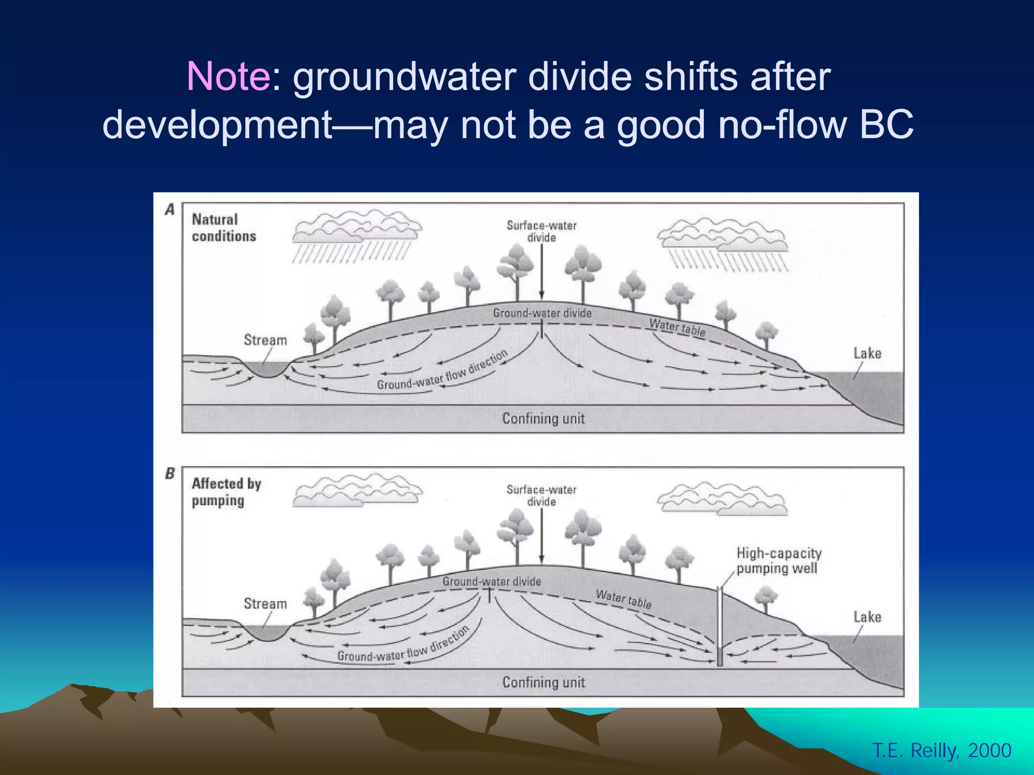
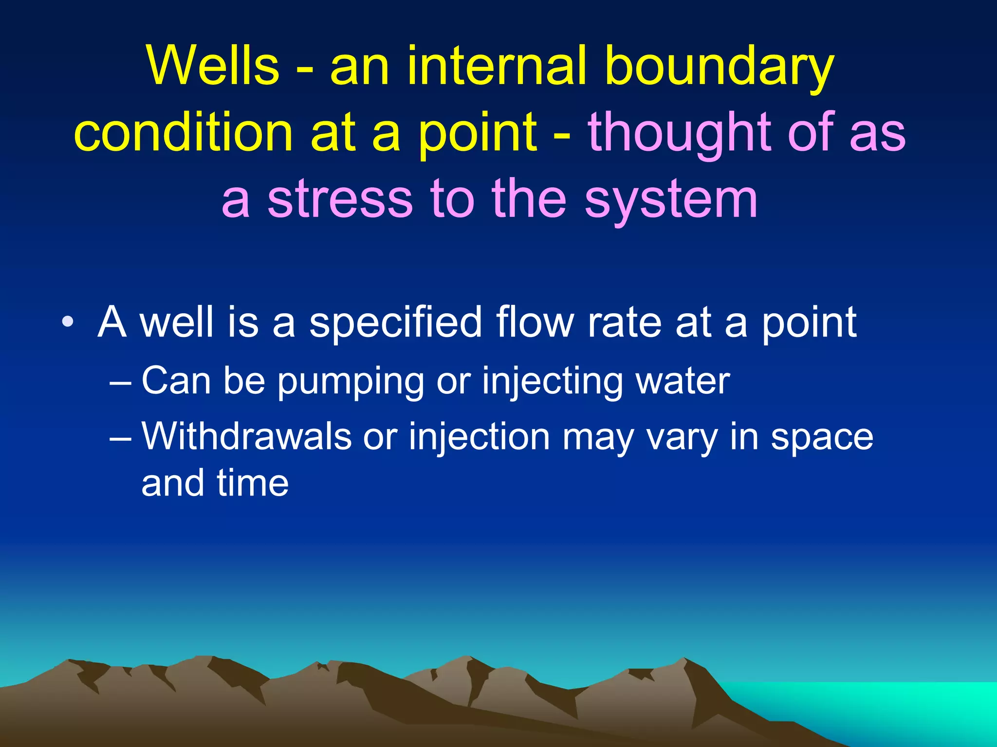


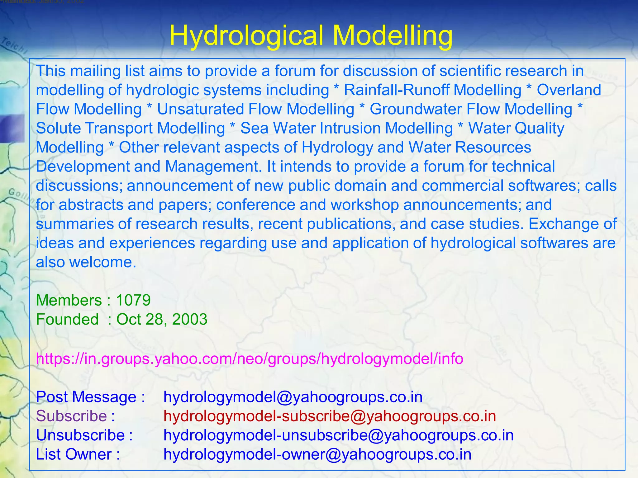
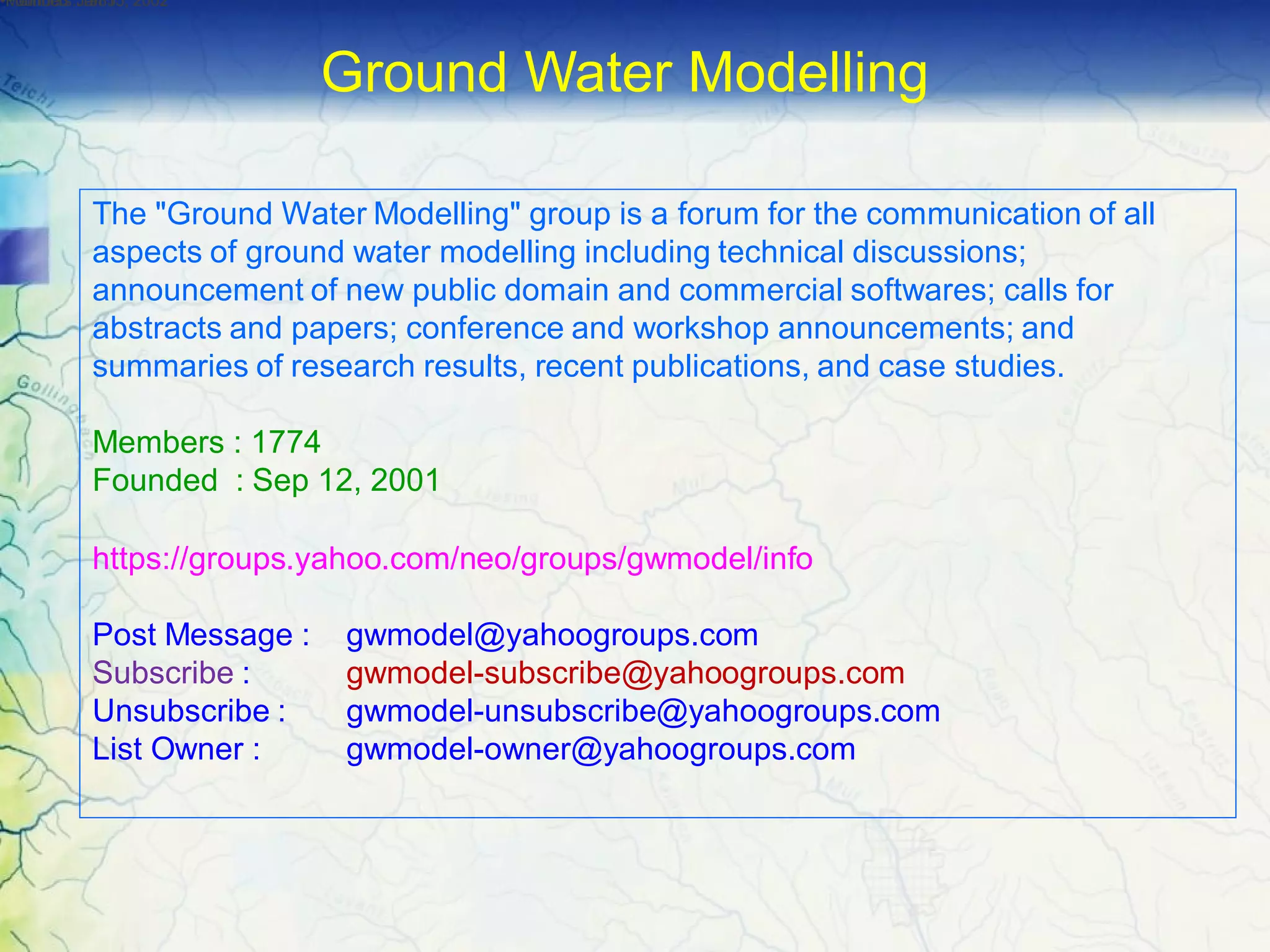

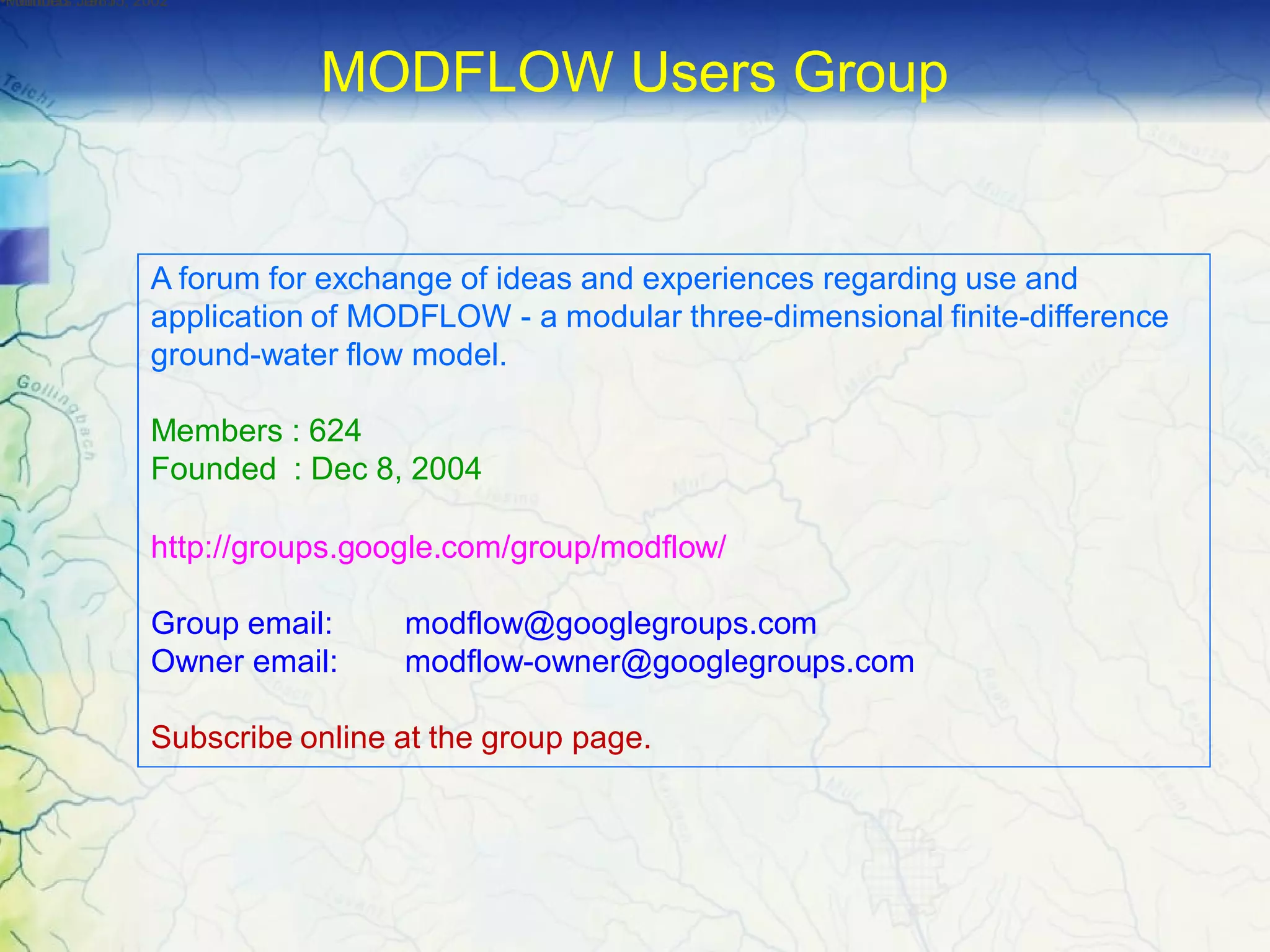


Groundwater modeling requires data on the physical and hydrological framework of the aquifer. The physical framework data defines the aquifer geometry and properties, including topography, geology, aquifer thickness and boundaries. The hydrological framework data describes the flow in and out of the aquifer, such as water table elevations, recharge and discharge rates and areas. Collecting these types of data from existing sources and monitoring programs is the first step of any groundwater modeling study.