Data Communications and Networks- OSI Reference Model
•
0 likes•9 views

Data Communications and Networks- OSI Reference Model

Recommended
More Related Content
Similar to Data Communications and Networks- OSI Reference Model
Similar to Data Communications and Networks- OSI Reference Model (20)
More from Chandrakant Divate
More from Chandrakant Divate (20)
Recently uploaded
Recently uploaded (20)
Data Communications and Networks- OSI Reference Model
- 1. 1 Mr. C. P. Divate Department of Computer Engineering
- 2. 2 OSI Reference Model OSI stands for Open System Interconnection is a reference model that describes how information from a software application in one computer moves through a physical medium to the software application in another computer. OSI consists of seven layers, and each layer performs a particular network function.
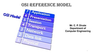
- 3. OSI model was developed by the International Organization for Standardization (ISO) in 1984, and it is now considered as an architectural model for the inter-computer communications. OSI model divides the whole task into seven smaller and manageable tasks. Each layer is assigned a particular task. Each layer is self-contained, so that task assigned to each layer can be performed independently. 3 OSI Reference Model 7. Application Layer 6. Presentation Layer 5. Session Layer 4. Transport Layer 3. Network Layer 2. Data Link Layer 1. Physical Layer
- 4. The OSI model is divided into two layers: upper layers and lower layers. Upper Layer: • The upper layer of the OSI model mainly deals with the application related issues, and they are implemented only in the software. • The application layer is closest to the end user. Both the end user and the application layer interact with the software applications. • An upper layer refers to the combination just above lower layer. Lower Layer: • The lower layer of the OSI model deals with the data transport issues. • The data link layer and the physical layer are implemented in hardware and software. • The physical layer is the lowest layer of the OSI model and is closest to the physical medium. • The physical layer is mainly responsible for placing the information on the physical medium. 4 Characteristics of OSI Model: Upper layer Lower layer
- 5. There are the seven OSI layers. Each layer has different functions. A list of seven layers are given below: 1) Physical Layer 2) Data-Link Layer 3) Network Layer 4) Transport Layer 5) Session Layer 6) Presentation Layer 7) Application Layer 5 Functions of the OSI Layers in OSI Model:
- 6. 6
- 7. 7
- 8. 8 The main functionality of the physical layer is to transmit the individual bits from one node to another node. It is the lowest layer of the OSI model. It establishes, maintains and deactivates the physical connection. Physical layer Host-1 Host-2
- 9. 9 Line Configuration: It defines the way how two or more devices can be connected physically (Wired/Wireless). Data Transmission: It defines the transmission mode whether it is simplex, half-duplex or full-duplex mode between the two devices on the network. Topology: It defines the way how network devices are arranged. Signals: It determines the type of the signal used for transmitting the information. Encoding: Digital to Analog / Light signal conversion at sender host for respective transmission medium Coaxial, Ethernet and Wi-Fi / Fiber Optic cable. Decoding: Analog / Light to Digital signal conversion at Receiver host for respective transmission medium Coaxial, Ethernet and Wi-Fi / Fiber Optic cable. Functions of a Physical layer:
- 10. 10 Examples of hardware in the physical layer are Cables, network adapters, ethernet, repeaters, networking hubs, switches, brides and routers etc. Components of a Physical layer: 1) Cables 1) Connectors Bayonet Neill–Concelman) registered jack 1) Connectors Name SC- subscriber connector LC- Line Construction FC- Ferrule Connector or Fiber Channel ST- straight tip
- 11. 11 Components of a Physical layer: Electromagnetic spectrum for type of signal on Transmission Medium on network
- 12. 12 Components of a Physical layer: AS per requirement of speed of data transmission Network designer have to select type of cable for computer network
- 13. 13 Examples of hardware in the physical layer are Cables, network adapters, ethernet, repeaters, networking hubs, switches, brides and routers etc. Components of a Physical layer: 2) Network Interface Card (NIC ) in HOST RJ45 Connector Port BNC Connector Port Fiber cable Connector Port Wi-Fi Connector Port
- 14. 14 Examples of hardware in the physical layer are Cables, network adapters, ethernet, repeaters, networking hubs, switches, brides and routers etc. Components of a Physical layer: 3) Repeater
- 15. 15 Examples of hardware in the physical layer are Cables, network adapters, ethernet, repeaters, networking hubs, switches, brides and routers etc. Components of a Physical layer: 4) HUB
- 16. 16 Examples of hardware in the physical layer are Cables, network adapters, ethernet, repeaters, networking hubs, switches, brides and routers etc. Components of a Physical layer: 5) Switch
- 17. 17 Components of a Physical layer: 7) Bridge
- 18. 18 Components of a Physical layer: 6) Bridge
- 19. 19 Components of a Physical layer: 6) Router
- 20. 20 Router Components of a Physical layer:
- 21. 21 Components of a Physical layer: 6) Router works in Unicast an Multicast Mode
- 22. 22 Components of a Physical layer: 7) Gateway
- 23. 23 Examples of hardware in the physical layer are Cables, network adapters, ethernet, repeaters, networking hubs, switches, brides and routers etc. Components of a Physical layer: Repeater 1) Repeater / Hub 2) Switch 3) Router 4) Gateway
- 24. 24
- 25. 1) Physical characteristics of interfaces and medium : the purpose of the physical layer is to transport a raw bit stream from one machine to another. Various physical media can be used for the actual transmission. Each one has its own position in terms of bandwidth, delay, cost, and ease of installation and maintenance. 2) Representation of bits : The physical layer data consists of a stream of bits (sequence of 0’s or 1’s) with no interpretation. To be transmitted, bits must be encoded into signals--electrical or optical. The physical layer defines the type of encoding (how 0’s and 1’s are changed to signals). 3) Data rate : The transmission rate-the number of bits sent each second-is also defined by the physical layer. In other words, the physical layer defines the duration of a bit, which is how long it takes for transmission over transmission medium. 25 Functions of a Physical layer in details: Major duties of the physical layer are as follows :
- 26. 4) Synchronization of bits : The sender and receiver not only must use the same bit rate but also must be synchronized at the bit level. In other words, the sender and the receiver clocks must be synchronized. 5) Line configuration : The physical layer is concerned with the connection of devices to the media. In a point-to-point configuration, two devices are connected through a dedicated link. In a multipoint configuration, a link is shared among several devices. 6) Physical topology : The physical topology defines how devices are connected to make a network. Devices can be connected by using a mesh topology (every device is connected to every other device) A star topology (devices are connected through a central device) A ring topology (each device is connected to the next, forming a ring) A bus topology (every device is on a common link) A hybrid topology (this is a combination of two or more topologies). 26 Functions of a Physical layer in details:
- 27. 7) Transmission mode : The physical layer also defines the direction of transmission between two devices: Simplex Half-duplex Full-duplex. In simplex mode, only one device can send and the other canonly receive. The simplex mode is a one-way communication. In the half-duplex mode, two devices can send and receive, but not at the same time. In a full-duplex (or simply duplex) mode, two devices can send and receive at the same time. 27 Functions of a Physical layer in details:
- 28. Media is a general term used to describe the data path that forms the physical channel between sender and receiver. Transmission media can be twisted pair wire such as that used for telephone installation, wire media are referred to as Bounded Media and wireless media are sometimes referred to as Unbounded Media. Bandwidth, noise, radiation and attenuation are considered while using the different transmission media. Higher bandwidth transmission media supports higher data rates. Attenuation limits the usable distance that data can travel on the media. Noise is related to electrical signal noise that can cause distortion of the data signal and data errors. 28
- 29. 14 Radiation is the leakage of signal from the media caused by undesirable electrical characteristic of the transmission media. The transmission medium is the physical path between transmitter and receiver in a data transmission system. In transmission medium, communication is in the form of electromagnetic waves. The characteristics and quality of transmission are determined both bythe characteristics of the medium and the characteristics of signal.
- 30. Design Factors: ◦ Bandwidth : The greater the bandwidth the higher the data rate can be achieved. ◦ Transmission Impairments : such as attenuation, limit the distance (repeater spacing) for guided media. Twisted pair generally suffer more impairment than co-axial cable. ◦ Interference ◦ Number of Receivers Guided or Unguided Media : ◦ Depending on the type of application and geographical situation suitable guided or unguided media is chosen. ◦ For long distance point-to-point transmission guided media are suitable. ◦ For long distance broadcasting transmission unguided media are chosen. 30
- 31. 31
- 32. 32 TP is least expensive and most widely used. TP consists of two insulated copper wire arranged in regular spiral pattern. A wire pair act as a signal communication link. TP may used to transmit both analog and digital signals. For analog signal amplifiers are required about every 5 to 6 km. for digital signals, repeaters are required every 2 or 3 km. TP is most commonly used medium for in the telephone network. Compared to other commonly used transmission media, TP is limited in distance, bandwidth and data rate when two copper wire conduct electric signal in close proximity, a certain amount of electromagnetic inference occurs (EMI). This type of inference is called Cross Talk. Twisting the copper wire reduces cross talk. Twisted pair cable comes in two varieties. Unshielded twisted pair (UTP) cable. Shielded twisted pair (STP) cable.
- 33. 18 UTP is a set of twisted pairs of cable within a plastic sheet. UTP is ordinary telephone wire. This is the least expensive of all the transmission media commonly used for LAN, and is easy to work with and simple to install. UTP is subject to external electromagnetic inference. Category 3 and category 5 UTP are commonly used in computer networks. UTP can transfer data at 1 to 100 Mbps over a distance of 100 meters. The difference between cat3 and cat5 cable is the number of twists in the cable per unit distance cat5 is much more tightly twisted. TP cable contains eight separate wires with four pairs. Four of them are solid colors (Blue, Green, Orange and Brown), while the other four are striped with white.
- 34. Category 5 : Used in local network. It supports upto 100 Mbps data transmission speed. Category 4 : It support transmission speed of 16 Mbps and three twist per foot. Category 3 : It supports data transmission speed upto 10 Mbps. Atleast three twist per feet and used in telephone system. Category 2 : It supports data transmission speed upto 4 Mbps and suitable for voice data transmission. Category 1 : mostly used in telephone system. Cat1 is suitable for voice and low speed data communication. 18
- 35. 18
- 36. CHARACTERISTICS OF UTP : Transmission rate of 10-100 Mbps. UTP is less expensive than FOC and co-axial cable. Maximum cable segment of UTP is 100 meters. UTP cable is very flexible and easy to work. Most susceptible to electrical interference or cross talk. 36 ADVANTAGES OF UTP: UTP is easy to terminate. Cost of installation is less. High installed base. DISADVANTAGES OF UTP : It is very noisy. It covers less distance. UTP suffers from interference.
- 37. 37 APPLICATION OF TP CABLES : Twisted Pair can used for both analog and digital signals. Twisted Pair cable are used in telephone network. In LAN, TP wires mainly use for low cost, low performance application. STP offers a protective sheathing around the copper wire. STP provides better performance at lower data rates. They are not commonly used in networks. Installation of STP is easy. Special connectors are required for installation. Cost is moderately expensive. Distance is limited to 100 meters for 500 meters. STP suffers from outside interference but not as much UTP.
- 38. 38 RJ45 is a type of connector commonly used for Ethernet networking. It looks similar to a telephone jack, but is slightly wider. Since Ethernet cables have an RJ45 connector on each end, Ethernet cables are sometimes also called RJ45 cables. The "RJ" in RJ45 stands for "registered jack," since it is a standardized networking interface. Each RJ45 connector has eight pins, which means an RJ45 cable contains eight separate wires. Four of them are solid colors (Blue, Green, Orange and Brown), while the other four are striped with white. Connector for Twisted Pair Cable RJ45
- 39. 39 Crimping of Twisted Pair Cable RJ45 Click to see the video Click to see how to Crimp Twisted Pair Cable with RJ45 connector RJ45 cables can be wired in two different ways. One version is called T-568A and the other is T-568B. These wiring standards are listed below:
- 40. It is made up of two conductors that shares the common axis. It consists of a hollow outer cylindrical conductor that surrounds a single inner wire conductor. Coaxial cable is used to transmit both analog and digital signals. Data transfer rate of coaxial cable is in between TP and FOC. It is relatively inexpensive. The cost for thin coaxial cable is less than STP. Thick coaxial cable must be grounded and terminated. A typical data rate for today’s coaxial network is 10 Mbps, although potential is higher. It suffers from attenuation.
- 41. Coaxial cable is classified by size (RG) and by the cable resistance to direct or alternative electric currents. RG means Rating Government. 50 ohm, RG-8 and RG-11 for thick Ethernet. 50 ohm, RG-58 used for thin Ethernet. 75 ohm, RG-59 used for cable TV. 93 ohm, RG-62 used for ARC net
- 43. 43 CHARACTERISTICS OF CO-AXIAL CABLE : 10 Mbps is transmission rate. Maximum cable length for thinnet is 185 meters and thicknet is 500 meters. Flexible and easy to work with thinnet for small distance. Ethernet designation to 10 base 2 (thinnet) or 10 base 5 (thicknet). Less expensive than FOC but more expensive than TP. Good resistance to electrical interference. APPLICATION OF CO-AXIAL CABLE : In analog and digital transmission. In telephone networks. In Ethernet LANs. In cable TV network.
- 44. 44 ADVANTAGES OF CO-AXIAL CABLE : Coaxial cable used for both data transmission i.e. analog and digital data transmission. It has higher bandwidth. Easy to handle and relatively inexpensive as compared to FOC. It uses for longer distance at higher data rates. Excellent noise immunity. DISADVANTAGES OF CO-AXIAL CABLE : Distance is limited. Number of nodes connection is limited. Proper connectors and termination is must.
- 45. 45 Coaxial cable connectors are used to connect cables to other devices. High-quality connectors offer reliable, long-lasting connections. There are two distinct connector styles; male and female. Male connectors have a protruding metal pin in the center, whereas female connectors have a receptacle to receive that pin. Within digital, video, audio, RF, and microwave industries, there are several varieties of coaxial cable connector types. Type of Connectors for Coaxial cable Following are the types of Coaxial Cables, 1) BNC Bayonet Neil-Concelman (BNC)- i. Originally designed for military use. ii. The coaxial connector used for quick connect/disconnect in RF equipment and test instruments like radio, television, and video signal. iii. are best suited for frequencies below 4GHz,
- 46. 46 Type of Connectors for Coaxial cable 2) TNC Threaded Neil-Concelman (TNC)- i. It is the threaded version of a BNC connector. ii. It performs better microwave frequencies than BNC connectors. iii. TNC Connectors are weatherproof, miniature units that operate up to 12 GHz and are commonly used in cellular phone and RF/antenna connections to resolve leakage and stability issues
- 47. 47 Striping of Coaxial Cable RJ45 Click to see the video Click to see how to striping coaxial Cable with BNC connector
- 48. Fiber optic cable is a cable that uses light signals for communication. Fiber optic is a cable that holds the optical fibers coated in plastic that are used to send the data by pulses of light. Fiber optics provide faster data transmission than copper wires. It is a light pipe which is used to carry a light beam from one place to another place. Light is an electromagnetic signal and can be modulated by information. since the frequency of light is extremely high hence it can be achieved with excellent reliability. The modulated light travel along the fiber and at the far end, are converted to an electrical signal by means of a photo electric cell. Thus the original input signal is recovered at the far end. 48
- 49. Basic elements of Fiber optic cable: Core: The optical fiber consists of a narrow strand of glass or plastic known as a core. A core is a light transmission area of the fiber. The more the area of the core, the more light will be transmitted into the fiber. Cladding: The concentric layer of glass is known as cladding. The main functionality of the cladding is to provide the lower refractive index at the core interface as to cause the reflection within the core so that the light waves are transmitted through the fiber. Jacket(Buffer): The protective coating consisting of plastic is known as a jacket. The main purpose of a jacket is to preserve the fiber strength, absorb shock and extra fiber protection. 49
- 50. FOC transmits light signal rather than electrical signals. Each fiber has a inner core of glass or plastic that conducts light. the inner core is surrounded by cladding, a layer of glass that reflects the light back into core. A cable may contain a single fiber, but often fibers are bundled together in the centre of the cable. FOC may be multimode or signal mode. Multimode fibers use multiple light paths whereas signal mode fibers allow a single light path and are typically used with laser signaling. It is more expansive and greater bandwidth. 50
- 51. 1) Plastic Core and Plastic Cladding 2) GlassCore with Plastic Cladding (often called PCS fiber, plastic-clad silica) 3) Glass Core and Glass Cladding. 51 Plastic fibers have several advantages over glass fibers. Plastic fibersare more flexible and, consequently, more rugged than glass. They are easy to install, can better withstand stress, are less expensive, and weight approximately 60% less than glass. The disadvantages of plastic fibersis their high attenuation characteristics; they do not propagate light as efficiently as glass. Plastic fibers are limited to relatively short runs, such as within a single building or a building complex. 1) Plastic Core and Plastic Cladding
- 52. 52 Fibers with glass cores exhibit low attenuation characteristics. PCS fibers are slightly better than SCS fibers. PCS fibers are less affected by radiation and are therefore more attractive to military applications. 2) PCS- Class Core and Plastic Cladding
- 53. 53 SCS fiber have the best propagation characteristics and they are easier to terminate than PCS fibers. SCS cables are the least rugged, and they are more susceptible to increase in attenuation when exposed to radiation. The selection of fiber for a given application is a function of specific system requirements. They are always trade-offs based on the economics and logistics of a particular application. 3) Glass Core and Glass Cladding.
- 54. Transmission rate of 100 Gbps. Not affected by the electrical interference. Most expensive cable. FOC support cable length of 10 km or more. It supports voice, video and data. It provides most secure media. Commonly used as backbones between buildings and token ring networks. Not very flexible, difficult to work. 54
- 55. Wide Bandwidth Low Losses Immune to Cross Talk Interference Immune Lightweight Small Size More Strength Security Long Distance Transmission Environment Immune Safe and Easy Installation Reliable Accuracy 55
- 56. High Initial Cost : The initial installation or setting up cost is very high compared to all other systems. Maintenance and Repairing Cost : The maintenance and repairing of fiber optics systems is not only difficult but expensive also. 56 Clicking for video to attach Fiber cable to connectors Terminate The Fiber optical cable to connector
- 57. 57 Types of Fiber Optical Cable Connectors • SC- subscriber connector • ST- straight tip • LC- Line Construction • FC- Ferrule Connector or Fiber Channel The main difference between APC and UPC connectors is the fiber endface. APC connectors feature a fiber endface that is polished at an eight-degree angle; UPC connectors are polished with no angle.
- 58. 58 An unguided transmission transmits the electromagnetic waves without using any physical medium. Therefore it is also known as wireless transmission. In unguided media, air is the media through which the electromagnetic energy can flow easily. Unguided transmission is broadly classified into three categories: 1) Radio waves 2) Microwaves 3) Infrared
- 59. 59
- 60. Radio waves are the electromagnetic waves that are transmitted in all the directions of free space. Radio waves are omnidirectional, i.e., the signals are propagated in all the directions. The range in frequencies of radio waves is from 10 Khz to 1 Ghz. In the case of radio waves, the sending and receiving antenna are not aligned, i.e., the wave sent by the sending antenna can be received by any receiving antenna. An example of the radio wave is FM radio. Radio waves includes following types : i. Short wave. ii. Very High Frequency (VHF) television and FM radio. iii. Ultra High Frequency (UHF) radio and television. Various kind of antennas can be used to broadcast radio signals. The power of the radio frequency signal is determined by the antenna and transreceiver (a device that transmit and receive a signal over a medium such a copper, radio waves, or fiber optic cables). 60
- 61. Radio waves are easy to generate. They can travel long distances. They can penetrate building easily so they are widely used for communication both indoor and outdoors. Radio waves are omni directional. The properties of radio waves are frequency dependent. At low frequencies, radio waves pass through obstacles well, but the power falls off sharply with distance from the source. At high frequencies, radio waves are subject to interference from motors and other electrical equipment. Low frequency and medium frequency range cannot be used for data transfer because of their very small bandwidth. 61
- 62. A Radio wave is useful for multicasting when there is one sender and many receivers. An FM radio, television, cordless phones are examples of a radio wave. 62 Applications Of Radio waves: Radio transmission is mainly used for wide area networks and mobile cellular phones. Radio waves cover a large area, and they can penetrate the walls. Radio transmission provides a higher transmission rate. Advantages Of Radio transmission:
- 63. Microwaves are of two types: Terrestrial microwave Satellite microwave communication. 63 Microwaves
- 64. Terrestrial Microwave transmission is a technology that transmits the focused beam of a radio signal from one ground-based microwave transmission antenna to another. Microwaves are the electromagnetic waves having the frequency in the range from 1GHz to 1000 GHz. Microwaves are unidirectional as the sending and receiving antenna is to be aligned, i.e., the waves sent by the sending antenna are narrowly focused. In this case, antennas are mounted on the towers to send a beam to another antenna which is km away. It works on the line of sight transmission, i.e., the antennas mounted on the towers are the direct sight of each other. 64 Terrestrial Microwave Transmission
- 65. Frequency range: The frequency range of terrestrial microwave is from 4-6 GHz to 21-23 GHz. Bandwidth: It supports the bandwidth from 1 to 10 Mbps. Short distance: It is inexpensive for short distance. Long distance: It is expensive as it requires a higher tower for a longer distance. Attenuation: Attenuation means loss of signal. It is affected by environmental conditions and antenna size. 65 Characteristics of Microwave:
- 66. 66 Design of Microwave Communication
- 67. 67 Design of Microwave Communication
- 68. Microwave transmission is cheaper than using cables. It is free from land acquisition as it does not require any land for the installation of cables. Microwave transmission provides an easy communication in terrains as the installation of cable in terrain is quite a difficult task. Communication over oceans can be achieved by using microwave transmission. 68 Advantages Of Microwave:
- 69. 69 Disadvantages Of Microwave: Eavesdropping: An eavesdropping creates insecure communication. Any malicious user can catch the signal in the air by using its own antenna. Out of phase signal: A signal can be moved out of phase by using microwave transmission. Susceptible to weather condition: A microwave transmission is susceptible to weather condition. This means that any environmental change such as rain, wind can distort the signal. Bandwidth limited: Allocation of bandwidth is limited in the case of microwave transmission.
- 70. Mobile telephone network uses microwave communication. Wireless LAN. Point-to-point communication between stations. Line –of sight communication. 70
- 71. 71 Satellite Microwave Communication A satellite is a physical object that revolves around the earth at a known height. Satellite communication is more reliable nowadays as it offers more flexibility than cable and fiber optic systems. We can communicate with any point on the globe by using satellite communication. How Does Satellite work? The satellite accepts the signal that is transmitted from the earth station, and it amplifies the signal. The amplified signal is retransmitted to another earth station.
- 72. 72 Advantages Of Satellite Microwave Communication: The coverage area of a satellite microwave is more than the terrestrial microwave. The transmission cost of the satellite is independent of the distance from the centre of the coverage area. Satellite communication is used in mobile and wireless communication applications. It is easy to install. It is used in a wide variety of applications such as weather forecasting, radio/TV signal broadcasting, mobile communication, etc.
- 73. 73 Disadvantages Of Satellite Microwave Communication: Satellite designing and development requires more time and higher cost. The Satellite needs to be monitored and controlled on regular periods so that it remains in orbit. The life of the satellite is about 12-15 years. Due to this reason, another launch of the satellite has to be planned before it becomes non-functional.
- 74. An infrared transmission is a wireless technology used for communication over short ranges. The frequency of the infrared in the range from 300 GHz to 400 THz. It is used for short-range communication such as data transfer between two cell phones, TV remote operation, data transfer between a computer, VCR and stereos all use infrared communication and cell phone resides in the same closed area. They do not pass through solid objects. An infrared system in one room of a building will not interfere with a similar system in adjacent rooms. Infrared light is suitable for indoor wireless. 74
- 75. It supports high bandwidth, and hence the data rate will be very high. Infrared waves cannot penetrate the walls. Therefore, the infrared communication in one room cannot be interrupted by the nearby rooms. An infrared communication provides better security with minimum interference. Infrared communication is unreliable outside the building because the sun rays will interfere with the infrared waves. 75 Characteristics Of Infrared:
- 76. The data link layer is responsible for moving frames from one hop (node) to the next. 76 This layer is responsible for the error-free transfer of data frames. It defines the format of the data on the network. It provides a reliable and efficient communication between two or more devices. It is mainly responsible for the unique identification of each device that resides on a local network.
- 77. 77 It contains two sub-layers: 1) Logical Link Control Layer It is responsible for transferring the packets to the Network layer of the receiver that is receiving. It identifies the address of the network layer protocol from the header. It also provides flow control. 2) Media Access Control Layer A Media access control layer is a link between the Logical Link Control layer and the network's physical layer. It is used for transferring the packets over the network.
- 78. 78 It contains two sub-layers: 1) Logical Link Control Layer 2) Media Access Control Layer
- 79. ▶Framing. The data link layer divides the stream of bits received from the network layer into manageable data units called frames. ▶ The DLL breaks the stream into discrete frames and computes the checksum for each frames. 79 ▶ At the destination the checksum is recomputed. ▶At breaking of bit stream by inserting spaces or time gaps is called framing. Since it is difficult and risky to count on timing and mark the start and end of each frame, various simple method used for framing are, ◦ Character count ◦ Starting and ending character, with character stuffing. ◦ Starting and ending flags, with bit stuffing. Functions of the Data-link layer
- 80. ▶Physical addressing. If frames are to be distributed to different systems on the network, the data link layer adds a header to the frame to define the sender and/or receiver of the frame. 80 ◦ If the frame is intended for a system outside the sender's network, the receiver address is the address of the device that connects the network to the next one. ▶Flow control. If the rate at which the data are absorbed by the receiver is less than the rate at which data are produced in the sender, the data link layer imposes a flow control mechanism to avoid overwhelming the receiver. ▶Flow control mechanism is incorporated which includes a feedback mechanism requesting transmitter a retransmission of incorrect message block. ▶ The most common retransmission technique is known as Automatic Repeat Request. ▶ Retransmission of data in three cases : ▶ Damaged frames ▶ Lost frames ▶ Lost acknowledgements.
- 81. ▶ Error control. The data link layer adds reliability to the physical layer by adding mechanisms to detect and retransmit damaged or lost frames. 81 ◦ It also uses a mechanism to recognize duplicate frames. ◦ Error control is normally achieved through a trailer added to the end of the frame. ▶ Access control. When two or more devices are connected to the same link, data link layer protocols are necessary to determine which device has control over the link at any given time.
- 82. ▶Improvement to ISO Model ▶ Logical Link Control (LLC) sub-layer 82 ◦ Manages service access points (logical link) ◦ Error and flow control ▶Media Access Control (MAC) sub-layer ◦ Applies directly to network card communication ◦ Access control
- 83. ▶ Network Interface Card driver 83 NETWORK SOFTWARE N ETWORK CARD NIC Driver facilitates data transfer
- 85. ▶The network layer is responsible for the delivery of individual packets from the source host to the destination host 85
- 86. 86
- 87. ▶ Logical addressing : The physical addressing implemented by the data link layer handles the addressing problem locally. If a packet passes the network boundary, we need another addressing system to help distinguish the source and destination systems. The network layer adds a header to the packet coming from the upper layer that, among other things, includes the logical addresses of the sender and receiver. ▶ The network layer functions are carried out by adding header to every Network Service Data Unit (NSDU) forming Network Protocol Data Unit (NPDU). The header contains all the information necessary for carrying out functions. 87
- 88. ▶ Routing : When independent networks or links are connected to create internetworks (network of networks) or a large network, the connecting devices (called routers or switches) route or switch the packets to their final destination. 88
- 89. ▶ Source-to- destination delivery 89
- 90. ▶The transport layer is responsible for the delivery of a message from one process to another. 90
- 91. 91
- 92. Service-point addressing. ▶ Computers often run several programs at the same time. ▶For this reason, source-to-destination delivery means delivery not only from one computer to the next but also from a specific process ( running program) on one computer to a specific process (running program) on the other. The transport layer header must therefore include a type of address called a service-point address (or port address). ▶ The network layer gets each packet to the correct computer; the transport layer gets the entire message to the correct process on that computer. 92
- 93. ▶ Segmentation and reassembly : A message is divided into transmittable segments, with each segment containing a sequence number. These numbers enable the transport layer to reassemble the message correctly upon arriving at the destination and to identify and replace packets that were lost in transmission. ▶ Connection control : The transport layer can be either connectionless or connection oriented. A connectionless transport layer treats each segment as an independent packet and delivers it to the transport layer at the destination machine. A connection oriented transport layer makes a connection with the transport layer at the destination machine first before delivering the packets. After all the data are transferred, the connection is terminated. 93
- 94. ▶Flow control : Like the data link layer, the transport layer is responsible for flow control. However, flow control at this layer is performed end to end rather than across a single link. ▶ Error control : Like the data link layer, the transport layer is responsible for error control. However, error control at this layer is performed process-to process rather than across a single link. The sending transport layer makes sure that the entire message arrives at the receiving transport layer without error (damage, loss, or duplication). ▶ Error correction is usually achieved through retransmission. 94
- 96. ▶The session layer is responsible for dialog control and synchronization 96
- 97. 97
- 98. Dialog control : The session layer allows two systems to enter into a dialog. ▶It allows the communication between two processes to take place in either half duplex (one way at a time) or full-duplex (two ways at a time) mode. Synchronization : The session layer allows a process to add checkpoints, or synchronization points, to a stream of data. ▶For example, if a system is sending a file of 2000 pages, it is advisable to insert checkpoints after every 100 pages to ensure that each 100-page unit is received and acknowledged independently. In this case, if a crash happens during the transmission of page 523, the only pages that need to be resent after system recovery are pages 501 to 523. Pages previous to 501 need not be resent. 98
- 99. ▶The presentation layer is responsible for translation, compression, and encryption. 99
- 100. 100
- 101. Translation : The processes (running programs) in two systems are usually exchanging information in the form of character strings, numbers, and so on. ▶ The information must be changed to bit streams before being transmitted. Because different computers use different encoding systems, the presentation layer is responsible for interoperability between these different encoding methods. ▶The presentation layer at the sender changes the information from its sender- dependent format into a common format. ▶The presentation layer at the receiving machine changes the common format into its receiver-dependent format. 101
- 102. Encryption : To carry sensitive information, a system must be able to ensure privacy. ▶Encryption means that the sender transforms the original information to another form and sends the resulting message out over the network. ▶Decryption reverses the original process to transform the message back to its original form. Compression : Data compression reduces the number of bits contained in the information. ▶Data compression becomes particularly important in the transmission of multimedia such as text, audio, and video. 102
- 103. ▶The application layer is responsible for providing services to the user 103
- 104. 104
- 105. ▶ Network virtual terminal : A network virtual terminal is a software version of a physical terminal, and it allows a user to log on to a remote host. ▶ To do so, the application creates a software emulation of a terminal at the remote host. ▶ The user's computer talks to the software terminal which, in turn, talks to the host, and vice versa. ▶The remote host believes it is communicating with one of its own terminals and allows the user to log on. ▶File transfer, access, and management : This application allows a user to access files in a remote host (to make changes or read data), to retrieve files from a remote computer for use in the local computer, and to manage or control files in a remote computer locally. 105
- 106. ▶Mail services : This application provides the basis for e- mail forwarding and storage. ▶Directory services : This application provides distributed database sources and access for global information about various objects and services. 106
- 107. ▶At each layer, additional information is added to the data packet ▶An example would be information related to the IP protocol that is added at Layer 3 107
- 108. Data Header 108 Trailer A general concept of packets serves as a prerequisite to the understanding of the ISO-OSI model.
- 109. ▶ Packet arrival information ▶Receiver’s address ▶Sender’s address ▶ Synchronization character 109
- 110. ▶ Error correction code ◦ Character oriented ◦ VRC (Parity Checking) • ▶ Packet oriented error correction codes ◦ LRC ◦ CRC 110
- 111. 111
- 112. 112