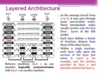
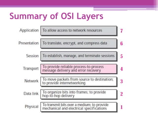
SlideShare a Scribd company logo
1 of 57
The OSI Model and
the TCP/IP Protocol Suite
OBJECTIVES
• To discuss the idea of multiple layering in data
communication and networking and the interrelationship
between layers.
• To discuss the OSI model and its layer architecture and
to show the interface between the layers.
• To briefly discuss the functions of each layer in the OSI
model.
• To introduce the TCP/IP protocol suite and compare its
layers with the ones in the OSI model.
• To show the functionality of each layer in the TCP/IP
protocol with some examples.
• To discuss the addressing mechanism used in some
layers of the TCP/IP protocol suite for the delivery of a
message from the source to the destination.
Introduction
• The layered model that dominated data communication
and networking literature before 1990 was the Open
Systems Interconnection (OSI) model. Everyone
believed that the OSI model would become the
ultimate standard for data communications—but this did
not happen. The TCP/IP protocol suite became the
dominant commercial architecture because it was
used and tested extensively in the Internet; the OSI
model was never fully implemented.
PROTOCOL LAYERS
• A protocol is required when two entities need to
communicate.
• When communication is not simple, we may
divide the complex task of communication
into several layers.
Example (face to face)
Assume Maria and Ann are neighbors with a lot of common
ideas.
• Example ( Different Cities)
• Now assume that Ann has to move to another town
because of her job.
PROTOCOL LAYERS
Protocol Hierarchies
• To reduce their design
complexity, most networks are
organized as a stack of layers
or levels, each one built upon
the one below it.
• The purpose of each layer is to
offer certain services to the
higher layers while shielding
those layers from the details of
how the offered services are
actually implemented.
• In reality, no data are directly
transferred from layer n on one
machine to layer n on another
machine.
The interface defines which
primitive operations and
services the lower layer makes
available to the upper one.
THE OSI MODEL
• This model is based on a proposal developed by the
International Standards Organization (ISO) as a first step
toward international standardization of the protocols
used in the various layers.
• The model is called the Open Systems Interconnection
(OSI) Reference Model because it deals with connecting
open systems. It was first introduced in the late 1970s.
• An open system is a set of protocols that allows any two
different systems to communicate regardless of their
underlying architecture.
• The purpose of the OSI model is to show how to
facilitate communication between different systems
without requiring changes to the logic of the underlying
hardware and software.
• The OSI model is not a protocol; it is a model for
understanding and designing a network architecture
that is flexible, robust, and interoperable.
• The OSI model is a layered framework for the design
of network systems that allows communication between
all types of computer systems.
THE OSI MODEL
• It consists of seven separate but related layers, each of
which defines a part of the process of moving
information across a network .
THE OSI MODEL
The network
support layers
The user
support layers
links the two
subgroups
Layered Architecture
• As the message travels from
A to B, it may pass through
many intermediate nodes.
These intermediate nodes
usually involve only the first
three layers of the OSI
model.
• Each layer defines a family
of functions distinct from
those of the other layers.
• Within a single machine,
each layer calls upon the
services of the layer just
below it. Layer 3, for
example, uses the services
provided by layer 2 and
provides services for layer 4.
Between machines, layer x on one
machine logically communicates
with layer x on another machine.
• Interfaces between Layers: Each interface
defines what information and services a layer
must provide for the layer above it.
• The upper OSI layers are almost always
implemented in software; lower layers are a
combination of hardware and software, except
for the physical layer, which is mostly hardware.
Layered Architecture
Encapsulation • The process starts at
layer 7 (the
application layer),
then moves from layer
to layer in descending,
sequential order. At
each layer, a header
can be added to the
data unit. At layer 2, a
trailer may also be
added. When the
formatted data unit
passes through the
physical layer (layer
1), it is changed into
an electromagnetic
signal and transported
along a physical link.
A packet at level 7 is encapsulated in the
packet at level 6. The whole packet at level 6 is
encapsulated in a packet at level 5, and so on.
Bits
Frame
Packet
Segment
Data Unit
PPDU
SPDU
Physical Layer (1)
• The physical layer coordinates the functions
required to carry a bit stream over a physical
medium.
• It deals with the mechanical and electrical
specifications of the interface and transmission
media.
• It also defines the procedures and functions that
physical devices and interfaces have to perform
for transmission to occur.
Physical characteristics of interfaces and media.
o The physical layer defines the characteristics of the interface
between the devices and the transmission media.
o It also defines the type of transmission media.
 Representation of bits.
o To be transmitted, bits must be encoded into signals—
electrical or optical. The physical layer defines the type of
encoding (how 0s and 1s are changed to signals).
 Data rate.
o The transmission rate—the number of bits sent each second.
 Synchronization of bits.
o the sender and the receiver clocks must be synchronized.
Line configuration (point-to-point, multipoint).
 Physical topology (mesh, bus, star, ring)
Transmission mode (simplex mode, half-duplex, full-
duplex)
Physical Layer (1)
• The data link layer transforms the physical layer,
a raw transmission facility, to a reliable link. It
makes the physical layer appear error-free to the
upper layer (network layer).
Framing.
• The data link layer divides the stream of bits received from the
network layer into manageable data units called frames.
Physical addressing.
▫ If frames are to be distributed to different systems on the
network, the data link layer adds a header to the frame to define
the sender and/or receiver of the frame. If the frame is
intended for a system outside the sender’s network, the
receiver address is the address of the connecting device
that connects the network to the next one.
Data Link Layer (2)
Data Link Layer (2)
Flow control.
o If the rate at which the data is absorbed by the receiver
is less than the rate produced at the sender, the data
link layer imposes a flow control mechanism to prevent
overwhelming the receiver.
Error control.
o The data link layer adds reliability to the physical layer by
adding mechanisms to detect and retransmit damaged or lost
frames. It also uses a mechanism to recognize duplicate
frames. Error control is normally achieved through a trailer
added to the end of the frame.
Access control.
o When two or more devices are connected to the same link,
data link layer protocols are necessary to determine which
device has control over the link at any given time.
Network Layer (3)
• The network layer is responsible for the source-to-
destination delivery of a packet, possibly across
multiple networks (links).
• Whereas the data link layer oversees the delivery of
the packet between two systems on the same network
(link), the network layer ensures that each packet gets
from its point of origin to its final destination.
• If two systems are connected to the same link, there is
usually no need for a network layer. However, if the
two systems are attached to different networks
(links) with connecting devices between the networks
(links), there is often a need for the network layer
to accomplish source-to-destination delivery.
Network Layer (3)
 Logical addressing.
o The physical addressing implemented by the data
link layer handles the addressing problem
locally. If a packet passes the network boundary, we
need another addressing system to help distinguish
the source and destination systems. The network layer
adds a header to the packet coming from the upper layer
that, among other things, includes the logical addresses
of the sender and receiver.
 Routing.
o When independent networks or links are connected
together to create internetworks (network of networks)
or a large network, the connecting devices (called
routers or switches) route or switch the packets to
their final destination. One of the functions of the
network layer is to provide this mechanism.
• The transport layer is responsible for process-to-
process delivery of the entire message. A process
is an application program running on the
host.
• The transport layer, ensures that the whole
message arrives intact and in order.
 Service-point addressing.
o The transport layer header must add a type of address
called a service-point address (or port address). The
network layer gets each packet to the correct
computer; the transport layer gets the entire message
to the correct process on that computer.
Transport Layer(4)
 Segmentation and reassembly.
o A message is divided into transmittable segments, with each
segment containing a sequence number. These numbers
enable the transport layer to reassemble the message
correctly upon arriving at the destination and to identify and
replace packets that were lost in transmission.
 Connection control.
o The transport layer can be either connectionless or connection-
oriented.
 Flow control.
o Like the data link layer, the transport layer is responsible for
flow control. However, flow control at this layer is performed
end to end rather than across a single link.
 Error control.
o Like the data link layer, the transport layer is responsible for
error control. However, error control at this layer is performed
process-to-process rather than across a single link. Error
correction is usually achieved through retransmission.
Transport Layer(4)
• The session layer is the network dialog controller. It
establishes, maintains, and synchronizes the interaction
between communicating systems.
 Dialog control.
• The session layer allows two systems to enter into a dialog. It
allows the communication between two processes to take place
in either half-duplex or full-duplex mode.
 Synchronization.
• The session layer allows a process to add checkpoints
(synchronization points) into a stream of data. For example, if a
system is sending a file of 2,000 pages, it is advisable to insert
checkpoints after every 100 pages to ensure that each 100-
page unit is received and acknowledged independently. In this
case, if a crash happens during the transmission of page 523, the
only pages that need to be resent after system recovery are pages
501 to 523. Pages previous to 501 need not be resent.
Session Layer(5)
• The presentation layer is concerned with the syntax and
semantics of the information exchanged between two
systems.
 Translation.
o The presentation layer is responsible for interoperability
between these different encoding methods.
o The presentation layer at the sender changes the
information from its sender-dependent format into a
common format. The presentation layer at the receiving
machine changes the common format into its receiver-
dependent format.
 Encryption.
 Compression.
Presentation Layer (6)
• The application layer enables the user, whether
human or software, to access the network.
• It provides user interfaces and support for
services such as electronic mail, remote file
access and transfer, shared database
management, and other types of
distributed information services.
Application Layer (7)
Summary of OSI Layers
TCP/IP PROTOCOL SUITE
• The first layered protocol model for internetwork
communications was created in the early 1970s and is
referred to as the Internet model. It defines four
categories of functions that must occur for
communications to be successful. The architecture of the
TCP/IP protocol suite follows the structure of this model.
Because of this, the Internet model is commonly referred
to as the TCP/IP model.
• The TCP/IP protocol suite was developed prior to the OSI
model. Therefore, the layers in the TCP/IP protocol suite
do not match exactly with those in the OSI model. The
original TCP/IP protocol suite was defined as four
software layers built upon the hardware.
TCP/IP PROTOCOL SUITE
• Today, TCP/IP is thought of as a five-layer model
with the layers named similarly to the ones in the
OSI model.
Comparison between OSI and TCP/IP
Protocol Suite • Here, two layers, session
and presentation, are
missing from the TCP/IP
protocol suite. These two
layers were not added to
the TCP/IP protocol suite
after the publication of
the OSI model. The
application layer in the
suite is usually
considered to be the
combination of three
layers in the OSI model.
Comparison between OSI and TCP/IP
Protocol Suite
• Two reasons were mentioned for this
decision.
• First, TCP/IP has more than one transport-layer protocol.
Some of the functionalities of the session layer are
available in some of the transport layer protocols.
• Second, the application layer is not only one piece of
software. Many applications can be developed at this layer.
If some of the functionalities mentioned in the session and
presentation are needed for a particular application, it can
be included in the development of that piece of software.
Layers in the TCP/IP Protocol Suite
• When we study the purpose of each layer, it is easier to think
of a private internet, instead of the global Internet. Such an
internet is made up of several small networks called links.
• A link is a network that allows a set of computers to
communicate with each other. A link can be a LAN or WAN.
• Our imaginary internet that is used to show the purpose of
each layer.
Physical Layer (1) TCP/IP
• TCP/IP does not define any specific protocol for the physical
layer. It supports all of the standard and proprietary protocols.
• At this level, the communication is between two
hops or nodes, either a computer or router.
• The unit of communication is a single bit. When the
connection is established between the two nodes, a stream of
bits is flowing between them. The physical layer, however,
treats each bit individually.
• We are assuming that at this moment the two computers
have discovered that the most efficient way to communicate
with each other is via routers R1, R3, and R4.
Physical Layer (1) TCP/IP
• Computer A sends
each bit to router R1
in the format of the
protocol used by
link 1. Router 1
sends each bit to
router R3 in the
format dictated by
the protocol used by
link 3. And so on.
• Note that if a node is
connected to n links,
it needs n physical-
layer protocols, one
for each link.
Physical Layer (1) TCP/IP
• TCP/IP does not define any specific protocol for the data
link layer either. It supports all of the standard and
proprietary protocols.
• At this level, the communication is also between
two hops or nodes. The unit of communication
however, is a packet called a frame.
• A frame is a packet that encapsulates the data received
from the network layer with an added header and
sometimes a trailer.
• The head includes the source and destination of frame.
The destination address is needed to define the right
recipient of the frame. The source address is needed for
possible response or acknowledgment as may be
required by some protocols.
Data Link Layer (2) TCP/IP
• Note that the frame that
is travelling between
computer A and router
R1 may be different
from the one travelling
between router R1 and
R3.
• When the frame is
received by router R1,
this router passes the
frame to the data link
layer protocol (left). The
frame is opened, the
data are removed.
• The data are then passed
to the data link layer
protocol (right) to create
a new frame to be sent
to the router R3.
Data Link Layer (2) TCP/IP
• At the network layer (or, more accurately, the
internetwork layer), TCP/IP supports the Internet
Protocol (IP).
• The Internet Protocol (IP) is the transmission mechanism
used by the TCP/IP protocols.
• IP transports data in packets called Datagrams, each of
which is transported separately. Datagrams can travel
along different routes and can arrive out of sequence or
be duplicated.
• IP does not keep track of the routes and has no facility for
reordering datagrams once they arrive at their
destination.
Network Layer(3) TCP/IP
• Note that there is a main difference between the
communication at the network layer and the
communication at data link or physical layers:
Communication at the network layer is end to end
while the communication at the other two layers are
node to node.
• The datagram started at computer A is the one that
reaches computer B. The network layers of the routers
can inspect (check) the source and destination of the
packet for finding the best route, but they are not
allowed to change the contents of the packet.
Network Layer(3) TCP/IP
• There is a main difference between the transport layer
and the network layer.
Although all nodes in a network need to have the
network layer, only the two end computers need
to have the transport layer.
• The network layer is responsible for sending individual
datagrams from computer A to computer B; the transport
layer is responsible for delivering the whole message,
which is called a Segment, a user datagram, or a packet,
from A to B.
• A segment may consist of a few or tens of
datagrams. The segments need to be broken into
datagrams and each datagram has to be delivered to the
network layer for transmission.
Transport Layer (4) TCP/IP
• Since the
Internet defines
a different route
for each
datagram, the
datagrams may
arrive out of
order and may
be lost. The
transport layer
at computer B
needs to wait
until all of these
datagrams to
arrive,
assemble them
and make a
segment out of
them.
Transport Layer (4) TCP/IP
• Traditionally, the transport layer was represented in
the TCP/IP suite by two protocols:
1- Transmission Control Protocol (TCP): is a reliable
connection-oriented protocol that allows a byte stream
originating on one machine to be delivered without error on any
other machine in the internet. TCP also handles flow control
to make sure a fast sender cannot swamp a slow receiver with
more messages than it can handle.
2- User Datagram Protocol (UDP): UDP is an unreliable,
connectionless protocol for applications that do not want
TCP’s sequencing or flow control and wish to provide their
own. It is also widely used for one-shot, client-server-type
request-reply queries and applications in which prompt
delivery is more important than accurate delivery, such as
transmitting speech or video. Its advantage low overhead.
3- A new protocol called Stream Control Transmission
Protocol (SCTP) has been introduced in the last few years.
Transport Layer (4) TCP/IP
• The application layer in TCP/IP is equivalent to the combined
session, presentation, and application layers in the OSI model.
The application layer allows a user to access the services of our
private internet or the global Internet. Many protocols are
defined at this layer to provide services such as electronic mail,
file transfer, accessing the World Wide Web, and so on.
• Note that the communication at the application layer, like the one
at the transport layer, is end to end. A message generated at
computer A is sent to computer B without being changed
during the transmission.
Application Layer (5) TCP/IP
Transport Layer (5) TCP/IP
• Four levels of addresses are used in an internet employing the
TCP/IP protocols: physical address, logical address,
port address, and application-specific address. Each
address is related to a one layer in the TCP/IP architecture:
ADDRESSING
• The physical address, also known as the link address, is the
address of a node as defined by its LAN or WAN. It is included
in the frame used by the data link layer. It is the lowest-level
address.
• The size and format of these addresses vary depending
on the network. For example, Ethernet uses a 6-byte
(48-bit) physical address that is imprinted on the
network interface card (NIC). LocalTalk (Apple), however,
has a 1-byte dynamic address that changes each time the
station comes up.
Physical Addresses
Physical Addresses
Layer 2 addresses are only used to communicate
between devices on a single local network
• Physical addresses can be either unicast (one single
recipient), multicast (a group of recipients), or
broadcast (to be received by all systems in the network).
• Some networks support all three addresses. Ethernet
supports the unicast physical addresses (6 bytes), the
multicast addresses, and the broadcast addresses.
• Some networks do not support the multicast or
broadcast physical addresses.
Unicast, Multicast, and Broadcast Physical Addresses
• Logical addresses are necessary for universal
communications that are independent of underlying
physical networks.
• Physical addresses are not adequate in an internetwork
environment where different networks can have different
address formats.
• A universal addressing system is needed in which each host
can be identified uniquely, regardless of the underlying
physical network. The logical addresses are designed for this
purpose.
• A logical address in the Internet is currently a 32-bit address
that can uniquely define a host connected to the Internet. No
two publicly addressed and visible hosts on the Internet can have
the same IP address.
Logical Addresses
• The network layer,
however, needs to
find the physical
address of the next
hop before the packet
can be delivered. The
network Layer
consults its routing
table and finds the
logical address of the
next hop to be F.
• Another protocol,
Address Resolution
Protocol (ARP),
finds the physical
address of router 1
that corresponds to its
logical address (20).
Logical Addresses
Logical Addresses
Unicast, Multicast, and Broadcast Addresses
 The logical addresses can be either unicast (one single
recipient), multicast (a group of recipients), or broadcast
(all systems in the network). There are limitations on
broadcast addresses.
Logical Addresses
• Computers are devices that can run multiple processes at
the same time. The end objective of Internet
communication is a process communicating with
another process.
• For example, computer A can communicate with
computer C by using TELNET. At the same time,
computer A communicates with computer B by using
the File Transfer Protocol (FTP).
• For these processes to receive data simultaneously, we
need a method to label the different processes. In the
TCP/IP architecture, the label assigned to a process is
called a port address. A port address in TCP/IP is 16
bits in length.
Port Addresses
• Port address is a
16-bit address
represented by
one decimal
number as
shown.
• 753 A 16-bit port
address
represented as
one single
number
Port Addresses
 Some of these Addresses are:
▫ Domain Name System (DNS) - TCP/UDP Port 53
▫ Hypertext Transfer Protocol (HTTP) - TCP Port 80
▫ Simple Mail Transfer Protocol (SMTP) - TCP Port 25
▫ Post Office Protocol (POP) - UDP Port 110 Telnet - TCP Port 23
▫ Dynamic Host Configuration Protocol - UDP Port 67
▫ File Transfer Protocol (FTP) - TCP Ports 20 and 21
For more:
CCNA Exploration 4.0 Network Fundamentals, Chapter Three
Application Layer functionality & Protocols (P. 24).
Port Addresses
• Some applications have user-friendly addresses that are
designed for that specific application.
• Examples include the e-mail address (for example,
forouzan@fhda.edu) and the Universal Resource Locator
(URL) (for example, www.mhhe.com). The first defines the
recipient of an e-mail; the second is used to find a document
on the World Wide Web.
• These addresses, however, get changed to the corresponding
port and logical addresses by the sending computer.
Application-Specific Addresses

More Related Content

Similar to Pwani notes-Network Essentials.pp for Internet Protocoltx

Class work 6,computer_network_317
Class work 6,computer_network_317Class work 6,computer_network_317
Class work 6,computer_network_317Khondoker Sadia
 
Chapter 1.2 osi model
Chapter 1.2 osi modelChapter 1.2 osi model
Chapter 1.2 osi modelNaiyan Noor
 
ET3003-2 OSI-TCPIP (Semester II 2013-2014)
ET3003-2 OSI-TCPIP (Semester II 2013-2014)ET3003-2 OSI-TCPIP (Semester II 2013-2014)
ET3003-2 OSI-TCPIP (Semester II 2013-2014)Tutun Juhana
 
Open system interference reference model.pptx
Open system interference reference model.pptxOpen system interference reference model.pptx
Open system interference reference model.pptxSwapnilGaikwad138578
 
OSI Model.It was created in 1983 by osi.
OSI Model.It was created in 1983 by osi.OSI Model.It was created in 1983 by osi.
OSI Model.It was created in 1983 by osi.muhammadsaudm19a
 
OSI Reference Model.pdf
OSI Reference Model.pdfOSI Reference Model.pdf
OSI Reference Model.pdfTamiratDejene1
 
Osi reference model
Osi reference modelOsi reference model
Osi reference modelSagar Gor
 
osireferencemodel-170703104058 (1).pdf
osireferencemodel-170703104058 (1).pdfosireferencemodel-170703104058 (1).pdf
osireferencemodel-170703104058 (1).pdfFira253524
 
OSI Reference Model and TCP/IP (Lecture #3 ET3003 Sem1 2014/2015)
OSI Reference Model and TCP/IP (Lecture #3 ET3003 Sem1 2014/2015)OSI Reference Model and TCP/IP (Lecture #3 ET3003 Sem1 2014/2015)
OSI Reference Model and TCP/IP (Lecture #3 ET3003 Sem1 2014/2015)Tutun Juhana
 
06 - OSI Model.ppt
06 - OSI Model.ppt06 - OSI Model.ppt
06 - OSI Model.pptssuserf7cd2b
 
06 - OSI Model.ppt
06 - OSI Model.ppt06 - OSI Model.ppt
06 - OSI Model.pptssuserf7cd2b
 

Similar to Pwani notes-Network Essentials.pp for Internet Protocoltx (20)

Class work 6,computer_network_317
Class work 6,computer_network_317Class work 6,computer_network_317
Class work 6,computer_network_317
 
Chapter 1.2 osi model
Chapter 1.2 osi modelChapter 1.2 osi model
Chapter 1.2 osi model
 
OSI model
OSI modelOSI model
OSI model
 
Osi model
Osi model Osi model
Osi model
 
Network architecture
Network architectureNetwork architecture
Network architecture
 
ET3003-2 OSI-TCPIP (Semester II 2013-2014)
ET3003-2 OSI-TCPIP (Semester II 2013-2014)ET3003-2 OSI-TCPIP (Semester II 2013-2014)
ET3003-2 OSI-TCPIP (Semester II 2013-2014)
 
OSI &TCP/IP Model
OSI &TCP/IP ModelOSI &TCP/IP Model
OSI &TCP/IP Model
 
Osi model
Osi modelOsi model
Osi model
 
Open system interference reference model.pptx
Open system interference reference model.pptxOpen system interference reference model.pptx
Open system interference reference model.pptx
 
Chap 2 network models
Chap 2 network modelsChap 2 network models
Chap 2 network models
 
OSI Model.It was created in 1983 by osi.
OSI Model.It was created in 1983 by osi.OSI Model.It was created in 1983 by osi.
OSI Model.It was created in 1983 by osi.
 
OSI Reference Model.pdf
OSI Reference Model.pdfOSI Reference Model.pdf
OSI Reference Model.pdf
 
OSI Model.pdf
OSI Model.pdfOSI Model.pdf
OSI Model.pdf
 
Basics of Ethernet
Basics of Ethernet Basics of Ethernet
Basics of Ethernet
 
Osi reference model
Osi reference modelOsi reference model
Osi reference model
 
osireferencemodel-170703104058 (1).pdf
osireferencemodel-170703104058 (1).pdfosireferencemodel-170703104058 (1).pdf
osireferencemodel-170703104058 (1).pdf
 
ch5-osi.pdf
ch5-osi.pdfch5-osi.pdf
ch5-osi.pdf
 
OSI Reference Model and TCP/IP (Lecture #3 ET3003 Sem1 2014/2015)
OSI Reference Model and TCP/IP (Lecture #3 ET3003 Sem1 2014/2015)OSI Reference Model and TCP/IP (Lecture #3 ET3003 Sem1 2014/2015)
OSI Reference Model and TCP/IP (Lecture #3 ET3003 Sem1 2014/2015)
 
06 - OSI Model.ppt
06 - OSI Model.ppt06 - OSI Model.ppt
06 - OSI Model.ppt
 
06 - OSI Model.ppt
06 - OSI Model.ppt06 - OSI Model.ppt
06 - OSI Model.ppt
 

Recently uploaded

Kotlin Multiplatform & Compose Multiplatform - Starter kit for pragmatics
Kotlin Multiplatform & Compose Multiplatform - Starter kit for pragmaticsKotlin Multiplatform & Compose Multiplatform - Starter kit for pragmatics
Kotlin Multiplatform & Compose Multiplatform - Starter kit for pragmaticscarlostorres15106
 
"LLMs for Python Engineers: Advanced Data Analysis and Semantic Kernel",Oleks...
"LLMs for Python Engineers: Advanced Data Analysis and Semantic Kernel",Oleks..."LLMs for Python Engineers: Advanced Data Analysis and Semantic Kernel",Oleks...
"LLMs for Python Engineers: Advanced Data Analysis and Semantic Kernel",Oleks...Fwdays
 
Making_way_through_DLL_hollowing_inspite_of_CFG_by_Debjeet Banerjee.pptx
Making_way_through_DLL_hollowing_inspite_of_CFG_by_Debjeet Banerjee.pptxMaking_way_through_DLL_hollowing_inspite_of_CFG_by_Debjeet Banerjee.pptx
Making_way_through_DLL_hollowing_inspite_of_CFG_by_Debjeet Banerjee.pptxnull - The Open Security Community
 
"Federated learning: out of reach no matter how close",Oleksandr Lapshyn
"Federated learning: out of reach no matter how close",Oleksandr Lapshyn"Federated learning: out of reach no matter how close",Oleksandr Lapshyn
"Federated learning: out of reach no matter how close",Oleksandr LapshynFwdays
 
Enhancing Worker Digital Experience: A Hands-on Workshop for Partners
Enhancing Worker Digital Experience: A Hands-on Workshop for PartnersEnhancing Worker Digital Experience: A Hands-on Workshop for Partners
Enhancing Worker Digital Experience: A Hands-on Workshop for PartnersThousandEyes
 
Connect Wave/ connectwave Pitch Deck Presentation
Connect Wave/ connectwave Pitch Deck PresentationConnect Wave/ connectwave Pitch Deck Presentation
Connect Wave/ connectwave Pitch Deck PresentationSlibray Presentation
 
CloudStudio User manual (basic edition):
CloudStudio User manual (basic edition):CloudStudio User manual (basic edition):
CloudStudio User manual (basic edition):comworks
 
SIEMENS: RAPUNZEL – A Tale About Knowledge Graph
SIEMENS: RAPUNZEL – A Tale About Knowledge GraphSIEMENS: RAPUNZEL – A Tale About Knowledge Graph
SIEMENS: RAPUNZEL – A Tale About Knowledge GraphNeo4j
 
My Hashitalk Indonesia April 2024 Presentation
My Hashitalk Indonesia April 2024 PresentationMy Hashitalk Indonesia April 2024 Presentation
My Hashitalk Indonesia April 2024 PresentationRidwan Fadjar
 
Transcript: #StandardsGoals for 2024: What’s new for BISAC - Tech Forum 2024
Transcript: #StandardsGoals for 2024: What’s new for BISAC - Tech Forum 2024Transcript: #StandardsGoals for 2024: What’s new for BISAC - Tech Forum 2024
Transcript: #StandardsGoals for 2024: What’s new for BISAC - Tech Forum 2024BookNet Canada
 
AI as an Interface for Commercial Buildings
AI as an Interface for Commercial BuildingsAI as an Interface for Commercial Buildings
AI as an Interface for Commercial BuildingsMemoori
 
New from BookNet Canada for 2024: BNC BiblioShare - Tech Forum 2024
New from BookNet Canada for 2024: BNC BiblioShare - Tech Forum 2024New from BookNet Canada for 2024: BNC BiblioShare - Tech Forum 2024
New from BookNet Canada for 2024: BNC BiblioShare - Tech Forum 2024BookNet Canada
 
Install Stable Diffusion in windows machine
Install Stable Diffusion in windows machineInstall Stable Diffusion in windows machine
Install Stable Diffusion in windows machinePadma Pradeep
 
Kotlin Multiplatform & Compose Multiplatform - Starter kit for pragmatics
Kotlin Multiplatform & Compose Multiplatform - Starter kit for pragmaticsKotlin Multiplatform & Compose Multiplatform - Starter kit for pragmatics
Kotlin Multiplatform & Compose Multiplatform - Starter kit for pragmaticsAndrey Dotsenko
 
Key Features Of Token Development (1).pptx
Key  Features Of Token  Development (1).pptxKey  Features Of Token  Development (1).pptx
Key Features Of Token Development (1).pptxLBM Solutions
 
Human Factors of XR: Using Human Factors to Design XR Systems
Human Factors of XR: Using Human Factors to Design XR SystemsHuman Factors of XR: Using Human Factors to Design XR Systems
Human Factors of XR: Using Human Factors to Design XR SystemsMark Billinghurst
 
Swan(sea) Song – personal research during my six years at Swansea ... and bey...
Swan(sea) Song – personal research during my six years at Swansea ... and bey...Swan(sea) Song – personal research during my six years at Swansea ... and bey...
Swan(sea) Song – personal research during my six years at Swansea ... and bey...Alan Dix
 
Artificial intelligence in the post-deep learning era
Artificial intelligence in the post-deep learning eraArtificial intelligence in the post-deep learning era
Artificial intelligence in the post-deep learning eraDeakin University
 

Recently uploaded (20)

Kotlin Multiplatform & Compose Multiplatform - Starter kit for pragmatics
Kotlin Multiplatform & Compose Multiplatform - Starter kit for pragmaticsKotlin Multiplatform & Compose Multiplatform - Starter kit for pragmatics
Kotlin Multiplatform & Compose Multiplatform - Starter kit for pragmatics
 
"LLMs for Python Engineers: Advanced Data Analysis and Semantic Kernel",Oleks...
"LLMs for Python Engineers: Advanced Data Analysis and Semantic Kernel",Oleks..."LLMs for Python Engineers: Advanced Data Analysis and Semantic Kernel",Oleks...
"LLMs for Python Engineers: Advanced Data Analysis and Semantic Kernel",Oleks...
 
Making_way_through_DLL_hollowing_inspite_of_CFG_by_Debjeet Banerjee.pptx
Making_way_through_DLL_hollowing_inspite_of_CFG_by_Debjeet Banerjee.pptxMaking_way_through_DLL_hollowing_inspite_of_CFG_by_Debjeet Banerjee.pptx
Making_way_through_DLL_hollowing_inspite_of_CFG_by_Debjeet Banerjee.pptx
 
"Federated learning: out of reach no matter how close",Oleksandr Lapshyn
"Federated learning: out of reach no matter how close",Oleksandr Lapshyn"Federated learning: out of reach no matter how close",Oleksandr Lapshyn
"Federated learning: out of reach no matter how close",Oleksandr Lapshyn
 
Enhancing Worker Digital Experience: A Hands-on Workshop for Partners
Enhancing Worker Digital Experience: A Hands-on Workshop for PartnersEnhancing Worker Digital Experience: A Hands-on Workshop for Partners
Enhancing Worker Digital Experience: A Hands-on Workshop for Partners
 
Connect Wave/ connectwave Pitch Deck Presentation
Connect Wave/ connectwave Pitch Deck PresentationConnect Wave/ connectwave Pitch Deck Presentation
Connect Wave/ connectwave Pitch Deck Presentation
 
CloudStudio User manual (basic edition):
CloudStudio User manual (basic edition):CloudStudio User manual (basic edition):
CloudStudio User manual (basic edition):
 
SIEMENS: RAPUNZEL – A Tale About Knowledge Graph
SIEMENS: RAPUNZEL – A Tale About Knowledge GraphSIEMENS: RAPUNZEL – A Tale About Knowledge Graph
SIEMENS: RAPUNZEL – A Tale About Knowledge Graph
 
My Hashitalk Indonesia April 2024 Presentation
My Hashitalk Indonesia April 2024 PresentationMy Hashitalk Indonesia April 2024 Presentation
My Hashitalk Indonesia April 2024 Presentation
 
Transcript: #StandardsGoals for 2024: What’s new for BISAC - Tech Forum 2024
Transcript: #StandardsGoals for 2024: What’s new for BISAC - Tech Forum 2024Transcript: #StandardsGoals for 2024: What’s new for BISAC - Tech Forum 2024
Transcript: #StandardsGoals for 2024: What’s new for BISAC - Tech Forum 2024
 
AI as an Interface for Commercial Buildings
AI as an Interface for Commercial BuildingsAI as an Interface for Commercial Buildings
AI as an Interface for Commercial Buildings
 
New from BookNet Canada for 2024: BNC BiblioShare - Tech Forum 2024
New from BookNet Canada for 2024: BNC BiblioShare - Tech Forum 2024New from BookNet Canada for 2024: BNC BiblioShare - Tech Forum 2024
New from BookNet Canada for 2024: BNC BiblioShare - Tech Forum 2024
 
Install Stable Diffusion in windows machine
Install Stable Diffusion in windows machineInstall Stable Diffusion in windows machine
Install Stable Diffusion in windows machine
 
The transition to renewables in India.pdf
The transition to renewables in India.pdfThe transition to renewables in India.pdf
The transition to renewables in India.pdf
 
Kotlin Multiplatform & Compose Multiplatform - Starter kit for pragmatics
Kotlin Multiplatform & Compose Multiplatform - Starter kit for pragmaticsKotlin Multiplatform & Compose Multiplatform - Starter kit for pragmatics
Kotlin Multiplatform & Compose Multiplatform - Starter kit for pragmatics
 
Key Features Of Token Development (1).pptx
Key  Features Of Token  Development (1).pptxKey  Features Of Token  Development (1).pptx
Key Features Of Token Development (1).pptx
 
Human Factors of XR: Using Human Factors to Design XR Systems
Human Factors of XR: Using Human Factors to Design XR SystemsHuman Factors of XR: Using Human Factors to Design XR Systems
Human Factors of XR: Using Human Factors to Design XR Systems
 
Swan(sea) Song – personal research during my six years at Swansea ... and bey...
Swan(sea) Song – personal research during my six years at Swansea ... and bey...Swan(sea) Song – personal research during my six years at Swansea ... and bey...
Swan(sea) Song – personal research during my six years at Swansea ... and bey...
 
Artificial intelligence in the post-deep learning era
Artificial intelligence in the post-deep learning eraArtificial intelligence in the post-deep learning era
Artificial intelligence in the post-deep learning era
 
E-Vehicle_Hacking_by_Parul Sharma_null_owasp.pptx
E-Vehicle_Hacking_by_Parul Sharma_null_owasp.pptxE-Vehicle_Hacking_by_Parul Sharma_null_owasp.pptx
E-Vehicle_Hacking_by_Parul Sharma_null_owasp.pptx
 

Pwani notes-Network Essentials.pp for Internet Protocoltx

  • 1. The OSI Model and the TCP/IP Protocol Suite
  • 2. OBJECTIVES • To discuss the idea of multiple layering in data communication and networking and the interrelationship between layers. • To discuss the OSI model and its layer architecture and to show the interface between the layers. • To briefly discuss the functions of each layer in the OSI model. • To introduce the TCP/IP protocol suite and compare its layers with the ones in the OSI model. • To show the functionality of each layer in the TCP/IP protocol with some examples. • To discuss the addressing mechanism used in some layers of the TCP/IP protocol suite for the delivery of a message from the source to the destination.
  • 3. Introduction • The layered model that dominated data communication and networking literature before 1990 was the Open Systems Interconnection (OSI) model. Everyone believed that the OSI model would become the ultimate standard for data communications—but this did not happen. The TCP/IP protocol suite became the dominant commercial architecture because it was used and tested extensively in the Internet; the OSI model was never fully implemented.
  • 4. PROTOCOL LAYERS • A protocol is required when two entities need to communicate. • When communication is not simple, we may divide the complex task of communication into several layers. Example (face to face) Assume Maria and Ann are neighbors with a lot of common ideas.
  • 5. • Example ( Different Cities) • Now assume that Ann has to move to another town because of her job. PROTOCOL LAYERS
  • 6. Protocol Hierarchies • To reduce their design complexity, most networks are organized as a stack of layers or levels, each one built upon the one below it. • The purpose of each layer is to offer certain services to the higher layers while shielding those layers from the details of how the offered services are actually implemented. • In reality, no data are directly transferred from layer n on one machine to layer n on another machine. The interface defines which primitive operations and services the lower layer makes available to the upper one.
  • 7. THE OSI MODEL • This model is based on a proposal developed by the International Standards Organization (ISO) as a first step toward international standardization of the protocols used in the various layers. • The model is called the Open Systems Interconnection (OSI) Reference Model because it deals with connecting open systems. It was first introduced in the late 1970s. • An open system is a set of protocols that allows any two different systems to communicate regardless of their underlying architecture.
  • 8. • The purpose of the OSI model is to show how to facilitate communication between different systems without requiring changes to the logic of the underlying hardware and software. • The OSI model is not a protocol; it is a model for understanding and designing a network architecture that is flexible, robust, and interoperable. • The OSI model is a layered framework for the design of network systems that allows communication between all types of computer systems. THE OSI MODEL
  • 9. • It consists of seven separate but related layers, each of which defines a part of the process of moving information across a network . THE OSI MODEL The network support layers The user support layers links the two subgroups
  • 10. Layered Architecture • As the message travels from A to B, it may pass through many intermediate nodes. These intermediate nodes usually involve only the first three layers of the OSI model. • Each layer defines a family of functions distinct from those of the other layers. • Within a single machine, each layer calls upon the services of the layer just below it. Layer 3, for example, uses the services provided by layer 2 and provides services for layer 4. Between machines, layer x on one machine logically communicates with layer x on another machine.
  • 11. • Interfaces between Layers: Each interface defines what information and services a layer must provide for the layer above it. • The upper OSI layers are almost always implemented in software; lower layers are a combination of hardware and software, except for the physical layer, which is mostly hardware. Layered Architecture
  • 12. Encapsulation • The process starts at layer 7 (the application layer), then moves from layer to layer in descending, sequential order. At each layer, a header can be added to the data unit. At layer 2, a trailer may also be added. When the formatted data unit passes through the physical layer (layer 1), it is changed into an electromagnetic signal and transported along a physical link. A packet at level 7 is encapsulated in the packet at level 6. The whole packet at level 6 is encapsulated in a packet at level 5, and so on. Bits Frame Packet Segment Data Unit PPDU SPDU
  • 13. Physical Layer (1) • The physical layer coordinates the functions required to carry a bit stream over a physical medium. • It deals with the mechanical and electrical specifications of the interface and transmission media. • It also defines the procedures and functions that physical devices and interfaces have to perform for transmission to occur.
  • 14. Physical characteristics of interfaces and media. o The physical layer defines the characteristics of the interface between the devices and the transmission media. o It also defines the type of transmission media.  Representation of bits. o To be transmitted, bits must be encoded into signals— electrical or optical. The physical layer defines the type of encoding (how 0s and 1s are changed to signals).  Data rate. o The transmission rate—the number of bits sent each second.  Synchronization of bits. o the sender and the receiver clocks must be synchronized. Line configuration (point-to-point, multipoint).  Physical topology (mesh, bus, star, ring) Transmission mode (simplex mode, half-duplex, full- duplex) Physical Layer (1)
  • 15. • The data link layer transforms the physical layer, a raw transmission facility, to a reliable link. It makes the physical layer appear error-free to the upper layer (network layer). Framing. • The data link layer divides the stream of bits received from the network layer into manageable data units called frames. Physical addressing. ▫ If frames are to be distributed to different systems on the network, the data link layer adds a header to the frame to define the sender and/or receiver of the frame. If the frame is intended for a system outside the sender’s network, the receiver address is the address of the connecting device that connects the network to the next one. Data Link Layer (2)
  • 16. Data Link Layer (2) Flow control. o If the rate at which the data is absorbed by the receiver is less than the rate produced at the sender, the data link layer imposes a flow control mechanism to prevent overwhelming the receiver. Error control. o The data link layer adds reliability to the physical layer by adding mechanisms to detect and retransmit damaged or lost frames. It also uses a mechanism to recognize duplicate frames. Error control is normally achieved through a trailer added to the end of the frame. Access control. o When two or more devices are connected to the same link, data link layer protocols are necessary to determine which device has control over the link at any given time.
  • 17. Network Layer (3) • The network layer is responsible for the source-to- destination delivery of a packet, possibly across multiple networks (links). • Whereas the data link layer oversees the delivery of the packet between two systems on the same network (link), the network layer ensures that each packet gets from its point of origin to its final destination. • If two systems are connected to the same link, there is usually no need for a network layer. However, if the two systems are attached to different networks (links) with connecting devices between the networks (links), there is often a need for the network layer to accomplish source-to-destination delivery.
  • 18. Network Layer (3)  Logical addressing. o The physical addressing implemented by the data link layer handles the addressing problem locally. If a packet passes the network boundary, we need another addressing system to help distinguish the source and destination systems. The network layer adds a header to the packet coming from the upper layer that, among other things, includes the logical addresses of the sender and receiver.  Routing. o When independent networks or links are connected together to create internetworks (network of networks) or a large network, the connecting devices (called routers or switches) route or switch the packets to their final destination. One of the functions of the network layer is to provide this mechanism.
  • 19. • The transport layer is responsible for process-to- process delivery of the entire message. A process is an application program running on the host. • The transport layer, ensures that the whole message arrives intact and in order.  Service-point addressing. o The transport layer header must add a type of address called a service-point address (or port address). The network layer gets each packet to the correct computer; the transport layer gets the entire message to the correct process on that computer. Transport Layer(4)
  • 20.  Segmentation and reassembly. o A message is divided into transmittable segments, with each segment containing a sequence number. These numbers enable the transport layer to reassemble the message correctly upon arriving at the destination and to identify and replace packets that were lost in transmission.  Connection control. o The transport layer can be either connectionless or connection- oriented.  Flow control. o Like the data link layer, the transport layer is responsible for flow control. However, flow control at this layer is performed end to end rather than across a single link.  Error control. o Like the data link layer, the transport layer is responsible for error control. However, error control at this layer is performed process-to-process rather than across a single link. Error correction is usually achieved through retransmission. Transport Layer(4)
  • 21. • The session layer is the network dialog controller. It establishes, maintains, and synchronizes the interaction between communicating systems.  Dialog control. • The session layer allows two systems to enter into a dialog. It allows the communication between two processes to take place in either half-duplex or full-duplex mode.  Synchronization. • The session layer allows a process to add checkpoints (synchronization points) into a stream of data. For example, if a system is sending a file of 2,000 pages, it is advisable to insert checkpoints after every 100 pages to ensure that each 100- page unit is received and acknowledged independently. In this case, if a crash happens during the transmission of page 523, the only pages that need to be resent after system recovery are pages 501 to 523. Pages previous to 501 need not be resent. Session Layer(5)
  • 22. • The presentation layer is concerned with the syntax and semantics of the information exchanged between two systems.  Translation. o The presentation layer is responsible for interoperability between these different encoding methods. o The presentation layer at the sender changes the information from its sender-dependent format into a common format. The presentation layer at the receiving machine changes the common format into its receiver- dependent format.  Encryption.  Compression. Presentation Layer (6)
  • 23. • The application layer enables the user, whether human or software, to access the network. • It provides user interfaces and support for services such as electronic mail, remote file access and transfer, shared database management, and other types of distributed information services. Application Layer (7)
  • 24. Summary of OSI Layers
  • 25. TCP/IP PROTOCOL SUITE • The first layered protocol model for internetwork communications was created in the early 1970s and is referred to as the Internet model. It defines four categories of functions that must occur for communications to be successful. The architecture of the TCP/IP protocol suite follows the structure of this model. Because of this, the Internet model is commonly referred to as the TCP/IP model. • The TCP/IP protocol suite was developed prior to the OSI model. Therefore, the layers in the TCP/IP protocol suite do not match exactly with those in the OSI model. The original TCP/IP protocol suite was defined as four software layers built upon the hardware.
  • 29. TCP/IP PROTOCOL SUITE • Today, TCP/IP is thought of as a five-layer model with the layers named similarly to the ones in the OSI model.
  • 30. Comparison between OSI and TCP/IP Protocol Suite • Here, two layers, session and presentation, are missing from the TCP/IP protocol suite. These two layers were not added to the TCP/IP protocol suite after the publication of the OSI model. The application layer in the suite is usually considered to be the combination of three layers in the OSI model.
  • 31. Comparison between OSI and TCP/IP Protocol Suite • Two reasons were mentioned for this decision. • First, TCP/IP has more than one transport-layer protocol. Some of the functionalities of the session layer are available in some of the transport layer protocols. • Second, the application layer is not only one piece of software. Many applications can be developed at this layer. If some of the functionalities mentioned in the session and presentation are needed for a particular application, it can be included in the development of that piece of software.
  • 32. Layers in the TCP/IP Protocol Suite • When we study the purpose of each layer, it is easier to think of a private internet, instead of the global Internet. Such an internet is made up of several small networks called links. • A link is a network that allows a set of computers to communicate with each other. A link can be a LAN or WAN. • Our imaginary internet that is used to show the purpose of each layer.
  • 33. Physical Layer (1) TCP/IP • TCP/IP does not define any specific protocol for the physical layer. It supports all of the standard and proprietary protocols. • At this level, the communication is between two hops or nodes, either a computer or router. • The unit of communication is a single bit. When the connection is established between the two nodes, a stream of bits is flowing between them. The physical layer, however, treats each bit individually.
  • 34. • We are assuming that at this moment the two computers have discovered that the most efficient way to communicate with each other is via routers R1, R3, and R4. Physical Layer (1) TCP/IP
  • 35. • Computer A sends each bit to router R1 in the format of the protocol used by link 1. Router 1 sends each bit to router R3 in the format dictated by the protocol used by link 3. And so on. • Note that if a node is connected to n links, it needs n physical- layer protocols, one for each link. Physical Layer (1) TCP/IP
  • 36. • TCP/IP does not define any specific protocol for the data link layer either. It supports all of the standard and proprietary protocols. • At this level, the communication is also between two hops or nodes. The unit of communication however, is a packet called a frame. • A frame is a packet that encapsulates the data received from the network layer with an added header and sometimes a trailer. • The head includes the source and destination of frame. The destination address is needed to define the right recipient of the frame. The source address is needed for possible response or acknowledgment as may be required by some protocols. Data Link Layer (2) TCP/IP
  • 37. • Note that the frame that is travelling between computer A and router R1 may be different from the one travelling between router R1 and R3. • When the frame is received by router R1, this router passes the frame to the data link layer protocol (left). The frame is opened, the data are removed. • The data are then passed to the data link layer protocol (right) to create a new frame to be sent to the router R3. Data Link Layer (2) TCP/IP
  • 38. • At the network layer (or, more accurately, the internetwork layer), TCP/IP supports the Internet Protocol (IP). • The Internet Protocol (IP) is the transmission mechanism used by the TCP/IP protocols. • IP transports data in packets called Datagrams, each of which is transported separately. Datagrams can travel along different routes and can arrive out of sequence or be duplicated. • IP does not keep track of the routes and has no facility for reordering datagrams once they arrive at their destination. Network Layer(3) TCP/IP
  • 40. • Note that there is a main difference between the communication at the network layer and the communication at data link or physical layers: Communication at the network layer is end to end while the communication at the other two layers are node to node. • The datagram started at computer A is the one that reaches computer B. The network layers of the routers can inspect (check) the source and destination of the packet for finding the best route, but they are not allowed to change the contents of the packet. Network Layer(3) TCP/IP
  • 41. • There is a main difference between the transport layer and the network layer. Although all nodes in a network need to have the network layer, only the two end computers need to have the transport layer. • The network layer is responsible for sending individual datagrams from computer A to computer B; the transport layer is responsible for delivering the whole message, which is called a Segment, a user datagram, or a packet, from A to B. • A segment may consist of a few or tens of datagrams. The segments need to be broken into datagrams and each datagram has to be delivered to the network layer for transmission. Transport Layer (4) TCP/IP
  • 42. • Since the Internet defines a different route for each datagram, the datagrams may arrive out of order and may be lost. The transport layer at computer B needs to wait until all of these datagrams to arrive, assemble them and make a segment out of them. Transport Layer (4) TCP/IP
  • 43. • Traditionally, the transport layer was represented in the TCP/IP suite by two protocols: 1- Transmission Control Protocol (TCP): is a reliable connection-oriented protocol that allows a byte stream originating on one machine to be delivered without error on any other machine in the internet. TCP also handles flow control to make sure a fast sender cannot swamp a slow receiver with more messages than it can handle. 2- User Datagram Protocol (UDP): UDP is an unreliable, connectionless protocol for applications that do not want TCP’s sequencing or flow control and wish to provide their own. It is also widely used for one-shot, client-server-type request-reply queries and applications in which prompt delivery is more important than accurate delivery, such as transmitting speech or video. Its advantage low overhead. 3- A new protocol called Stream Control Transmission Protocol (SCTP) has been introduced in the last few years. Transport Layer (4) TCP/IP
  • 44. • The application layer in TCP/IP is equivalent to the combined session, presentation, and application layers in the OSI model. The application layer allows a user to access the services of our private internet or the global Internet. Many protocols are defined at this layer to provide services such as electronic mail, file transfer, accessing the World Wide Web, and so on. • Note that the communication at the application layer, like the one at the transport layer, is end to end. A message generated at computer A is sent to computer B without being changed during the transmission. Application Layer (5) TCP/IP
  • 46. • Four levels of addresses are used in an internet employing the TCP/IP protocols: physical address, logical address, port address, and application-specific address. Each address is related to a one layer in the TCP/IP architecture: ADDRESSING
  • 47. • The physical address, also known as the link address, is the address of a node as defined by its LAN or WAN. It is included in the frame used by the data link layer. It is the lowest-level address. • The size and format of these addresses vary depending on the network. For example, Ethernet uses a 6-byte (48-bit) physical address that is imprinted on the network interface card (NIC). LocalTalk (Apple), however, has a 1-byte dynamic address that changes each time the station comes up. Physical Addresses
  • 48. Physical Addresses Layer 2 addresses are only used to communicate between devices on a single local network
  • 49. • Physical addresses can be either unicast (one single recipient), multicast (a group of recipients), or broadcast (to be received by all systems in the network). • Some networks support all three addresses. Ethernet supports the unicast physical addresses (6 bytes), the multicast addresses, and the broadcast addresses. • Some networks do not support the multicast or broadcast physical addresses. Unicast, Multicast, and Broadcast Physical Addresses
  • 50. • Logical addresses are necessary for universal communications that are independent of underlying physical networks. • Physical addresses are not adequate in an internetwork environment where different networks can have different address formats. • A universal addressing system is needed in which each host can be identified uniquely, regardless of the underlying physical network. The logical addresses are designed for this purpose. • A logical address in the Internet is currently a 32-bit address that can uniquely define a host connected to the Internet. No two publicly addressed and visible hosts on the Internet can have the same IP address. Logical Addresses
  • 51. • The network layer, however, needs to find the physical address of the next hop before the packet can be delivered. The network Layer consults its routing table and finds the logical address of the next hop to be F. • Another protocol, Address Resolution Protocol (ARP), finds the physical address of router 1 that corresponds to its logical address (20). Logical Addresses
  • 52. Logical Addresses Unicast, Multicast, and Broadcast Addresses  The logical addresses can be either unicast (one single recipient), multicast (a group of recipients), or broadcast (all systems in the network). There are limitations on broadcast addresses.
  • 54. • Computers are devices that can run multiple processes at the same time. The end objective of Internet communication is a process communicating with another process. • For example, computer A can communicate with computer C by using TELNET. At the same time, computer A communicates with computer B by using the File Transfer Protocol (FTP). • For these processes to receive data simultaneously, we need a method to label the different processes. In the TCP/IP architecture, the label assigned to a process is called a port address. A port address in TCP/IP is 16 bits in length. Port Addresses
  • 55. • Port address is a 16-bit address represented by one decimal number as shown. • 753 A 16-bit port address represented as one single number Port Addresses
  • 56.  Some of these Addresses are: ▫ Domain Name System (DNS) - TCP/UDP Port 53 ▫ Hypertext Transfer Protocol (HTTP) - TCP Port 80 ▫ Simple Mail Transfer Protocol (SMTP) - TCP Port 25 ▫ Post Office Protocol (POP) - UDP Port 110 Telnet - TCP Port 23 ▫ Dynamic Host Configuration Protocol - UDP Port 67 ▫ File Transfer Protocol (FTP) - TCP Ports 20 and 21 For more: CCNA Exploration 4.0 Network Fundamentals, Chapter Three Application Layer functionality & Protocols (P. 24). Port Addresses
  • 57. • Some applications have user-friendly addresses that are designed for that specific application. • Examples include the e-mail address (for example, forouzan@fhda.edu) and the Universal Resource Locator (URL) (for example, www.mhhe.com). The first defines the recipient of an e-mail; the second is used to find a document on the World Wide Web. • These addresses, however, get changed to the corresponding port and logical addresses by the sending computer. Application-Specific Addresses