Download to read offline

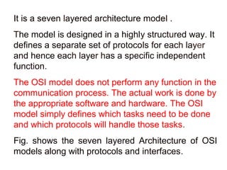
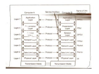

The OSI Reference Model describes a 7-layer network architecture developed by ISO to standardize network communication globally. It defines separate protocols for each layer to define tasks and responsibilities. The physical layer is responsible for sending bits between systems by defining encoding, transmission rates, and hardware details. The data link layer provides error checking, frame creation, and hardware addressing. The network layer establishes logical connections between systems, performs routing, handles addressing, and switches packets between networks.


![Computer Network [OSI Model]](https://cdn.slidesharecdn.com/ss_thumbnails/note-06cn-210605131126-thumbnail.jpg?width=640&height=640&fit=bounds)