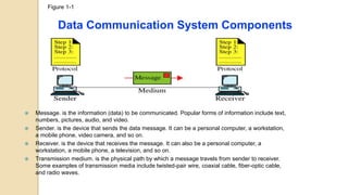
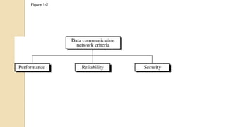
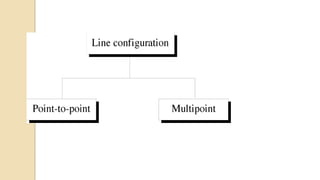
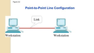
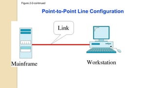
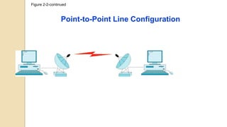
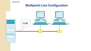
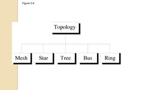
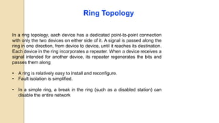
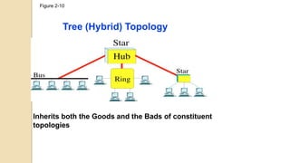
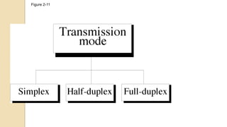
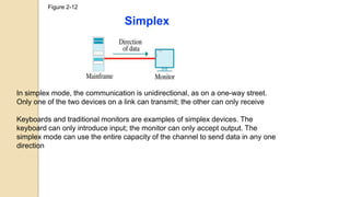
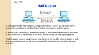
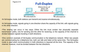
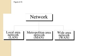
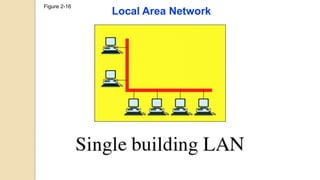
Bayero University , Kano CSC7307 Computer Communication & Networks
Computer Communication and
Networks (CSC7303)
DEPARTMENT OF COMPUTER SCIENCE,
Bayero University, Kano.
1
A. A. Datti
Bayero University , Kano CSC7307 Computer Communication & Networks
Course outline
 Basic Concepts
 Network Models
 Physical Layer
◦ Transmission Medium
◦ Data Transmission
 Data Link Layer
 Network Layer
 Transport Layer
 Application Layer
Bayero University , Kano CSC7307 Computer Communication & Networks
Introduction
 Data communications are the exchange of data between two
devices via some form of transmission medium such as a wire
cable.
 For data communications to occur, the communicating devices
must be part of a communication system (known as a data
communications network) made up of a combination of hardware
(physical equipment) and software (programs).
3
Bayero University , Kano CSC7307 Computer Communication & Networks
Communication Channel
 Uses electromagnetic signals to transmit messages
 Speed of electricity dramatically extends reach
◦ Sound waves: 343 m/s
◦ Electromagnetic waves: 299 792 458 m/s (speed of light)
◦ Sun to earth (149.6 billion meters) in 8 seconds
4
Figure 1-1
Data Communication System Components
 Message. is the information (data) to be communicated. Popular forms of information include text,
numbers, pictures, audio, and video.
 Sender. is the device that sends the data message. It can be a personal computer, a workstation,
a mobile phone, video camera, and so on.
 Receiver. is the device that receives the message. It can also be a personal computer, a
workstation, a mobile phone, a television, and so on.
 Transmission medium. is the physical path by which a message travels from sender to receiver.
Some examples of transmission media include twisted-pair wire, coaxial cable, fiber-optic cable,
and radio waves.
6
•Text is represented as a sequence of bits (Os or Is). Different sets of
bit patterns have been designed to represent text symbols such as in
the Unicode coding system , which uses 32 bits to represent a symbol
or character used in any language in the world.
•Numbers are also represented by bit patterns. However, the number is
directly converted to a binary number to simplify mathematical
operations.
Data Representation
7
Images are also represented by bit patterns. In its simplest form, an
image is composed of a matrix of pixels (picture elements), where each
pixel is a small dot. Each pixel is assigned a bit pattern.
For example, to show four levels of gray scale, you can use 2-bit
patterns. A black pixel can be represented by 00, a dark gray pixel by
01, a light gray pixel by 10, and a white pixel by 11.
Data Representation
8
•Audio is by nature different from text, numbers, or images. It is
continuous, not discrete. We subsequently learn how to convert
sound to a digital or an analog signal.
•Video: refers to the recording or broadcasting of a picture or
movie. Again we can change video to a digital or an analog signal,
as we will see subsequently.
Data Representation
Figure 1-2
Figure 1-2
Performance
•can be measured in many ways, including
•transit time : Transit time is the amount of time required for a message to
travel from one device to another
•response time: Response time is the elapsed time between an inquiry
and a response.
•depends on a number of factors,
•the number of users
•the type of transmission medium
•the capabilities of the connected hardware
•and the efficiency of the software.
•often evaluated by two networking metrics: throughput (volume of data) and
delay. We often need more throughput and less delay (time taken). However,
these two criteria are often contradictory.
Reliability In addition to accuracy of delivery, network
reliability is measured by the frequency of failure, the time it
takes a link to recover from a failure, and the network's
robustness in a catastrophe.
Security Network security issues include protecting data from
unauthorized access, protecting data from damage and
development, and implementing policies and procedures for
recovery from breaches and data losses.
•Point-to-Point provides a dedicated link between two devices. The entire
capacity of the link is reserved for transmission between those two devices.
When you change television channels by infrared remote control, you are
establishing a point-to-point connection between the remote control and the
television's control system.
•Multipoint A multipoint (also called multidrop) connection is one in which
more than two specific devices share a single link. In a multipoint environment,
the capacity of the channel is shared, either spatially or temporally. If several
devices can use the link simultaneously, it is a spatially shared connection. If
users must take turns, it is a timeshared connection.
Figure 2-2
Point-to-Point Line Configuration
Figure 2-2-continued
Point-to-Point Line Configuration
Figure 2-2-continued
Point-to-Point Line Configuration
Figure 2-3
Multipoint Line Configuration
Figure 2-4
Figure 2-5
Mesh Topology
Figure 2-5
Mesh Topology
In a mesh topology, every device has a dedicated point-to-point link to every other device
The number of physical links required in a fully connected mesh network with n nodes, we need
n(n -1) /2 links for full duplex and n(n -1) for simplex and n-1 network ports on each node.
Advantages:
Reduced Traffic
Robustness.
Privacy and security.
Easy fault identification and fault isolation
Disadvantages :
installation and reconnection are difficult
Large Space requirement due to bulk wiring
Expensive hardware
Figure 2-6
Star Topology
Figure 2-6
Star Topology
A star topology is less expensive than a mesh topology. In a star, each
device needs only one link and one I/O port to connect it to any number
of others.
Advantages:
easy to install and reconfigure.
Far less cabling needs to be housed,
Disadvantages
the dependency of the whole topology on one single point, the hub. If the
hub goes down, the whole system is dead.
Figure 2-8
Bus Topology
Figure 2-8
Bus Topology
The preceding examples all describe point-to-point connections. A bus
topology, on the other hand, is multipoint. One long cable acts as a backbone to
link all the devices in a network.
Nodes are connected to the bus cable by drop lines and taps
Advantages
Ease of installation
Disadvantages
Difficult reconnection and fault isolation.
Signal reflection at the taps can cause degradation in quality.
A fault or break in the bus cable stops all transmission
Figure 2-9
Ring Topology
Ring Topology
In a ring topology, each device has a dedicated point-to-point connection
with only the two devices on either side of it. A signal is passed along the
ring in one direction, from device to device, until it reaches its destination.
Each device in the ring incorporates a repeater. When a device receives a
signal intended for another device, its repeater regenerates the bits and
passes them along
• A ring is relatively easy to install and reconfigure.
• Fault isolation is simplified.
• In a simple ring, a break in the ring (such as a disabled station) can
disable the entire network
Figure 2-10
Tree (Hybrid) Topology
Inherits both the Goods and the Bads of constituent
topologies
Figure 2-11
Figure 2-12
Simplex
In simplex mode, the communication is unidirectional, as on a one-way street.
Only one of the two devices on a link can transmit; the other can only receive
Keyboards and traditional monitors are examples of simplex devices. The
keyboard can only introduce input; the monitor can only accept output. The
simplex mode can use the entire capacity of the channel to send data in any one
direction
Figure 2-13
Half-Duplex
In half-duplex mode, each station can both transmit and receive, but not at the same
time. When one device is sending, the other can only receive, and vice versa
In a half-duplex transmission, the entire capacity of a channel is taken over by whichever
of the two devices is transmitting at the time. Walkie-talkies are half-duplex systems.
The half-duplex mode is used in cases where there is no need for communication in both
directions at the same time; the entire capacity of the channel can be utilized for each
direction.
Figure 2-14
Full-Duplex
•In full-duplex mode, both stations can transmit and receive simultaneously.
•In full-duplex mode, signals going in one direction share the capacity of the link: with signals going
in the other direction.
•This sharing can occur in two ways: Either the link must contain two physically separate
transmission paths, one for sending and the other for receiving; or the capacity of the channel is
divided between signals traveling in both directions.
•One common example of full-duplex communication is the telephone network. When two people
are communicating by a telephone line, both can talk and listen at the same time. The full-duplex
mode is used when communication in both directions is required all the time. The capacity of the
channel, however, must be divided between the two directions.
Figure 2-15
Figure 2-16
Local Area Network
Figure 2-16-continued
Local Area Network
Local Area Network
A local area network (LAN) is usually privately owned and links the devices in a single
office, building, or campus. Depending on the needs of an organization and the type of
technology used, a LAN can be as simple as two PCs and a printer in someone's home
office; or it can extend throughout a company and include audio and video peripherals.
Currently, LAN size is limited to a few kilometers.
In addition to size, LANs are distinguished from other types of networks by their
transmission media and topology. In general, a given LAN will use only one type of
transmission medium. The most common LAN topologies are bus, ring, and star.
Early LANs had data rates in the 4 to 16 megabits per second (Mbps) range. Today,
however, speeds are normally 100 or 1000 Mbps.
Wireless LANs are the newest evolution in LAN technology.
Figure 2-17
Metropolitan Area Network
Figure 2-17
Metropolitan Area Network
A metropolitan area network (MAN) is a network with a size between a
LAN and a WAN. It normally covers the area inside a town or a city. It
is designed for customers who need a high-speed connectivity,
normally to the Internet, and have endpoints spread over a city or part
of city
Figure 2-18
Wide Area Network
Figure 2-18
Wide Area Network
A wide area network (WAN) provides long-distance transmission
of data, image, audio, and video information over large
geographic areas that may comprise a country, a continent, or
even the whole world.
Figure 2-19
Internetwork
(Internet)
Figure 2-19
Internetwork
(Internet)
Today, it is very rare to see a LAN, a MAN, or a LAN in isolation;
they are connected to one another. When two or more networks
are connected, they become an internetwork, or internet
Bayero University , Kano CSC7307 Computer Communication & Networks
Internet
 Internet evolved from ARPANET
 Developed to solve the dilemma of communicating across
arbitrary, multiple, packet-switched network
 TCP/IP provides the foundation
Bayero University , Kano CSC7307 Computer Communication & Networks
Internet – Key Elements
Bayero University , Kano CSC7307 Computer Communication & Networks
Internet Architecture

Basic Concepts of Networking.pptx

  • 1.
    Bayero University ,Kano CSC7307 Computer Communication & Networks Computer Communication and Networks (CSC7303) DEPARTMENT OF COMPUTER SCIENCE, Bayero University, Kano. 1 A. A. Datti
  • 2.
    Bayero University ,Kano CSC7307 Computer Communication & Networks Course outline  Basic Concepts  Network Models  Physical Layer ◦ Transmission Medium ◦ Data Transmission  Data Link Layer  Network Layer  Transport Layer  Application Layer
  • 3.
    Bayero University ,Kano CSC7307 Computer Communication & Networks Introduction  Data communications are the exchange of data between two devices via some form of transmission medium such as a wire cable.  For data communications to occur, the communicating devices must be part of a communication system (known as a data communications network) made up of a combination of hardware (physical equipment) and software (programs). 3
  • 4.
    Bayero University ,Kano CSC7307 Computer Communication & Networks Communication Channel  Uses electromagnetic signals to transmit messages  Speed of electricity dramatically extends reach ◦ Sound waves: 343 m/s ◦ Electromagnetic waves: 299 792 458 m/s (speed of light) ◦ Sun to earth (149.6 billion meters) in 8 seconds 4
  • 5.
    Figure 1-1 Data CommunicationSystem Components  Message. is the information (data) to be communicated. Popular forms of information include text, numbers, pictures, audio, and video.  Sender. is the device that sends the data message. It can be a personal computer, a workstation, a mobile phone, video camera, and so on.  Receiver. is the device that receives the message. It can also be a personal computer, a workstation, a mobile phone, a television, and so on.  Transmission medium. is the physical path by which a message travels from sender to receiver. Some examples of transmission media include twisted-pair wire, coaxial cable, fiber-optic cable, and radio waves.
  • 6.
    6 •Text is representedas a sequence of bits (Os or Is). Different sets of bit patterns have been designed to represent text symbols such as in the Unicode coding system , which uses 32 bits to represent a symbol or character used in any language in the world. •Numbers are also represented by bit patterns. However, the number is directly converted to a binary number to simplify mathematical operations. Data Representation
  • 7.
    7 Images are alsorepresented by bit patterns. In its simplest form, an image is composed of a matrix of pixels (picture elements), where each pixel is a small dot. Each pixel is assigned a bit pattern. For example, to show four levels of gray scale, you can use 2-bit patterns. A black pixel can be represented by 00, a dark gray pixel by 01, a light gray pixel by 10, and a white pixel by 11. Data Representation
  • 8.
    8 •Audio is bynature different from text, numbers, or images. It is continuous, not discrete. We subsequently learn how to convert sound to a digital or an analog signal. •Video: refers to the recording or broadcasting of a picture or movie. Again we can change video to a digital or an analog signal, as we will see subsequently. Data Representation
  • 9.
  • 10.
    Figure 1-2 Performance •can bemeasured in many ways, including •transit time : Transit time is the amount of time required for a message to travel from one device to another •response time: Response time is the elapsed time between an inquiry and a response. •depends on a number of factors, •the number of users •the type of transmission medium •the capabilities of the connected hardware •and the efficiency of the software. •often evaluated by two networking metrics: throughput (volume of data) and delay. We often need more throughput and less delay (time taken). However, these two criteria are often contradictory.
  • 11.
    Reliability In additionto accuracy of delivery, network reliability is measured by the frequency of failure, the time it takes a link to recover from a failure, and the network's robustness in a catastrophe. Security Network security issues include protecting data from unauthorized access, protecting data from damage and development, and implementing policies and procedures for recovery from breaches and data losses.
  • 13.
    •Point-to-Point provides adedicated link between two devices. The entire capacity of the link is reserved for transmission between those two devices. When you change television channels by infrared remote control, you are establishing a point-to-point connection between the remote control and the television's control system. •Multipoint A multipoint (also called multidrop) connection is one in which more than two specific devices share a single link. In a multipoint environment, the capacity of the channel is shared, either spatially or temporally. If several devices can use the link simultaneously, it is a spatially shared connection. If users must take turns, it is a timeshared connection.
  • 14.
  • 15.
  • 16.
  • 17.
  • 18.
  • 19.
  • 20.
    Figure 2-5 Mesh Topology Ina mesh topology, every device has a dedicated point-to-point link to every other device The number of physical links required in a fully connected mesh network with n nodes, we need n(n -1) /2 links for full duplex and n(n -1) for simplex and n-1 network ports on each node. Advantages: Reduced Traffic Robustness. Privacy and security. Easy fault identification and fault isolation Disadvantages : installation and reconnection are difficult Large Space requirement due to bulk wiring Expensive hardware
  • 21.
  • 22.
    Figure 2-6 Star Topology Astar topology is less expensive than a mesh topology. In a star, each device needs only one link and one I/O port to connect it to any number of others. Advantages: easy to install and reconfigure. Far less cabling needs to be housed, Disadvantages the dependency of the whole topology on one single point, the hub. If the hub goes down, the whole system is dead.
  • 23.
  • 24.
    Figure 2-8 Bus Topology Thepreceding examples all describe point-to-point connections. A bus topology, on the other hand, is multipoint. One long cable acts as a backbone to link all the devices in a network. Nodes are connected to the bus cable by drop lines and taps Advantages Ease of installation Disadvantages Difficult reconnection and fault isolation. Signal reflection at the taps can cause degradation in quality. A fault or break in the bus cable stops all transmission
  • 25.
  • 26.
    Ring Topology In aring topology, each device has a dedicated point-to-point connection with only the two devices on either side of it. A signal is passed along the ring in one direction, from device to device, until it reaches its destination. Each device in the ring incorporates a repeater. When a device receives a signal intended for another device, its repeater regenerates the bits and passes them along • A ring is relatively easy to install and reconfigure. • Fault isolation is simplified. • In a simple ring, a break in the ring (such as a disabled station) can disable the entire network
  • 27.
    Figure 2-10 Tree (Hybrid)Topology Inherits both the Goods and the Bads of constituent topologies
  • 28.
  • 29.
    Figure 2-12 Simplex In simplexmode, the communication is unidirectional, as on a one-way street. Only one of the two devices on a link can transmit; the other can only receive Keyboards and traditional monitors are examples of simplex devices. The keyboard can only introduce input; the monitor can only accept output. The simplex mode can use the entire capacity of the channel to send data in any one direction
  • 30.
    Figure 2-13 Half-Duplex In half-duplexmode, each station can both transmit and receive, but not at the same time. When one device is sending, the other can only receive, and vice versa In a half-duplex transmission, the entire capacity of a channel is taken over by whichever of the two devices is transmitting at the time. Walkie-talkies are half-duplex systems. The half-duplex mode is used in cases where there is no need for communication in both directions at the same time; the entire capacity of the channel can be utilized for each direction.
  • 31.
    Figure 2-14 Full-Duplex •In full-duplexmode, both stations can transmit and receive simultaneously. •In full-duplex mode, signals going in one direction share the capacity of the link: with signals going in the other direction. •This sharing can occur in two ways: Either the link must contain two physically separate transmission paths, one for sending and the other for receiving; or the capacity of the channel is divided between signals traveling in both directions. •One common example of full-duplex communication is the telephone network. When two people are communicating by a telephone line, both can talk and listen at the same time. The full-duplex mode is used when communication in both directions is required all the time. The capacity of the channel, however, must be divided between the two directions.
  • 32.
  • 33.
  • 34.
  • 35.
    Local Area Network Alocal area network (LAN) is usually privately owned and links the devices in a single office, building, or campus. Depending on the needs of an organization and the type of technology used, a LAN can be as simple as two PCs and a printer in someone's home office; or it can extend throughout a company and include audio and video peripherals. Currently, LAN size is limited to a few kilometers. In addition to size, LANs are distinguished from other types of networks by their transmission media and topology. In general, a given LAN will use only one type of transmission medium. The most common LAN topologies are bus, ring, and star. Early LANs had data rates in the 4 to 16 megabits per second (Mbps) range. Today, however, speeds are normally 100 or 1000 Mbps. Wireless LANs are the newest evolution in LAN technology.
  • 36.
  • 37.
    Figure 2-17 Metropolitan AreaNetwork A metropolitan area network (MAN) is a network with a size between a LAN and a WAN. It normally covers the area inside a town or a city. It is designed for customers who need a high-speed connectivity, normally to the Internet, and have endpoints spread over a city or part of city
  • 38.
  • 39.
    Figure 2-18 Wide AreaNetwork A wide area network (WAN) provides long-distance transmission of data, image, audio, and video information over large geographic areas that may comprise a country, a continent, or even the whole world.
  • 40.
  • 41.
    Figure 2-19 Internetwork (Internet) Today, itis very rare to see a LAN, a MAN, or a LAN in isolation; they are connected to one another. When two or more networks are connected, they become an internetwork, or internet
  • 42.
    Bayero University ,Kano CSC7307 Computer Communication & Networks Internet  Internet evolved from ARPANET  Developed to solve the dilemma of communicating across arbitrary, multiple, packet-switched network  TCP/IP provides the foundation
  • 43.
    Bayero University ,Kano CSC7307 Computer Communication & Networks Internet – Key Elements
  • 44.
    Bayero University ,Kano CSC7307 Computer Communication & Networks Internet Architecture