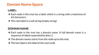
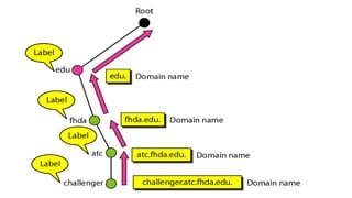
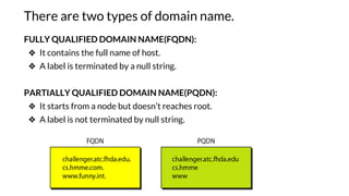
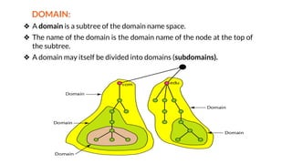
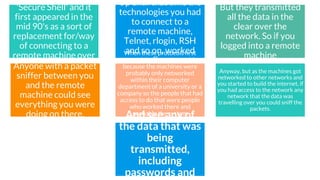
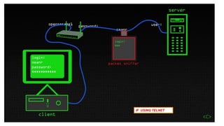
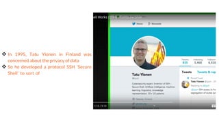
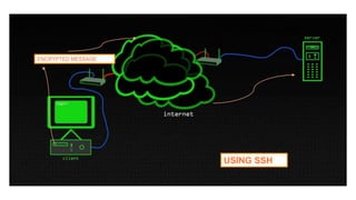
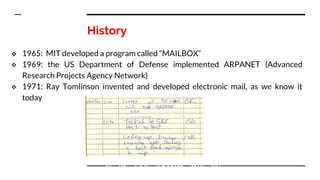
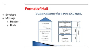
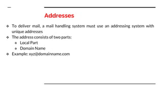
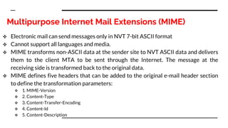
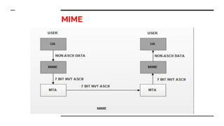
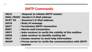
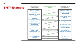
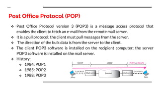
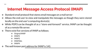
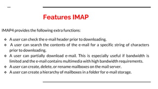
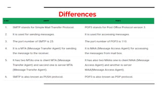
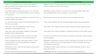
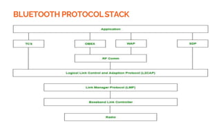
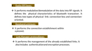
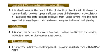
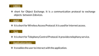
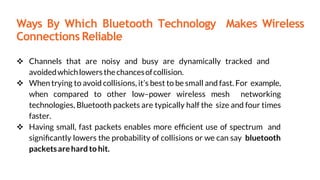
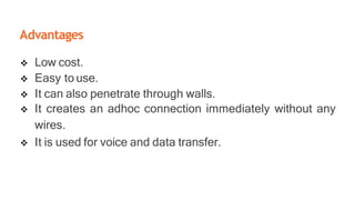
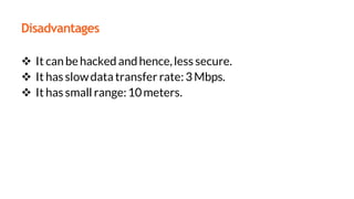
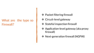
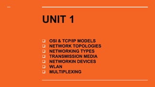
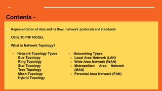
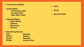
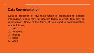
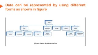
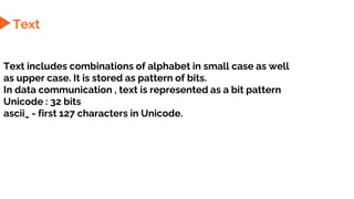
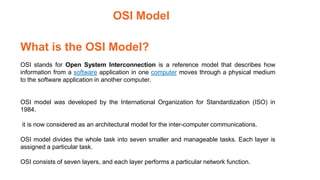
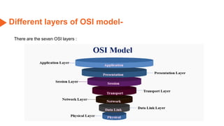
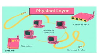
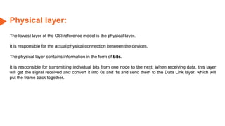
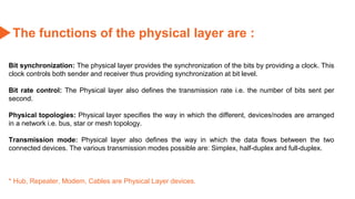
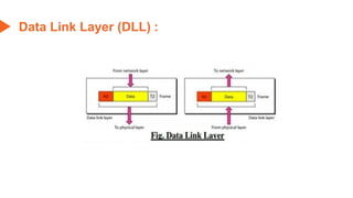
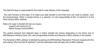
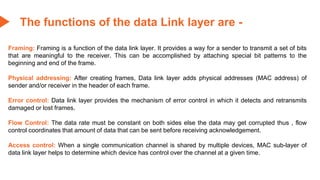
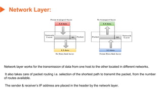
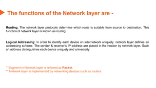
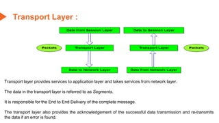
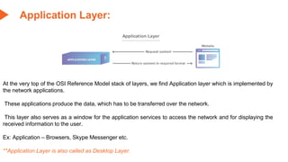
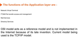
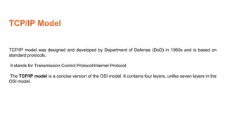
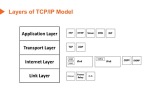
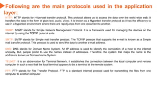
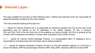
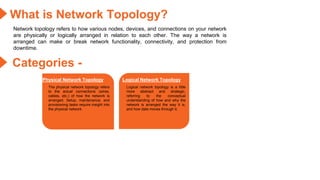
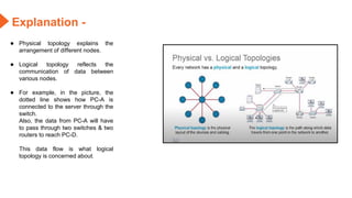
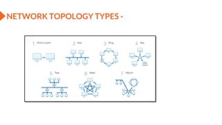
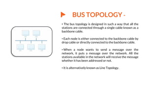
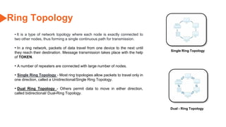
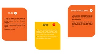
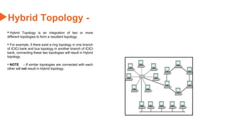
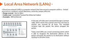
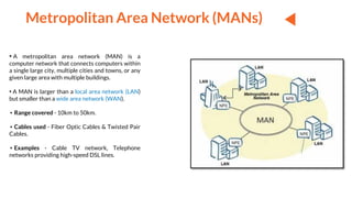
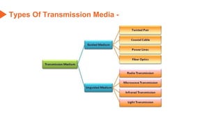
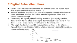
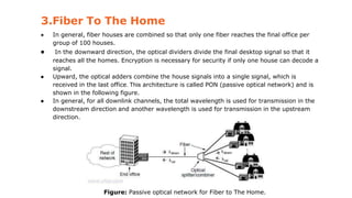
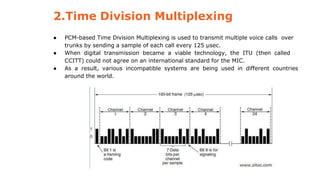
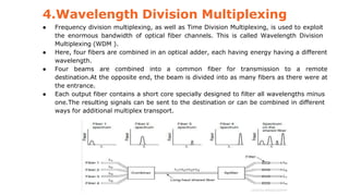
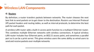
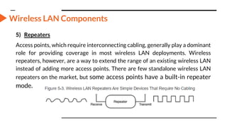
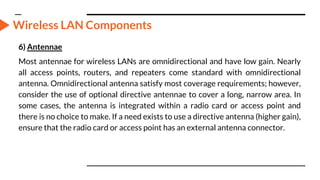
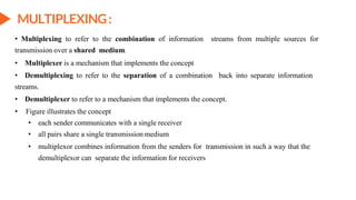
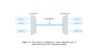
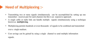
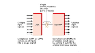
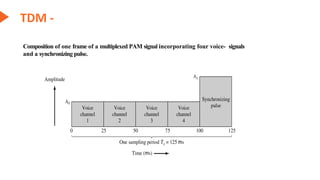
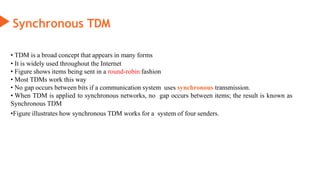
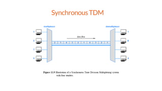
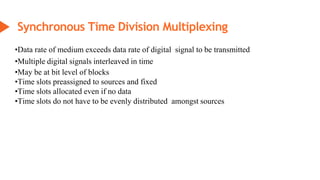
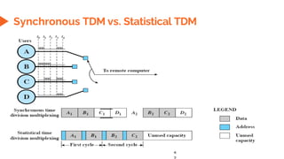
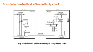
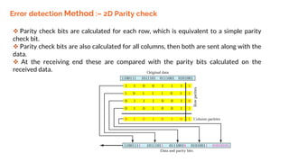
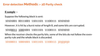
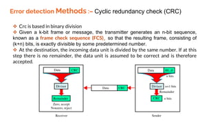
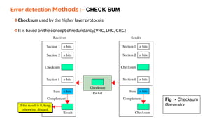
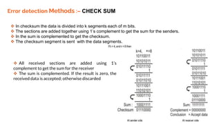
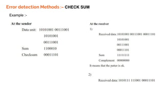
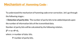
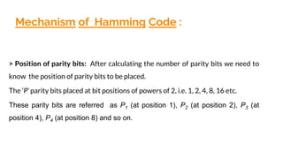
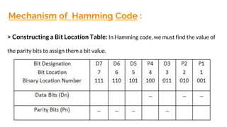
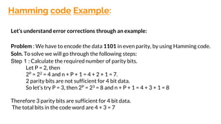
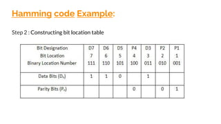
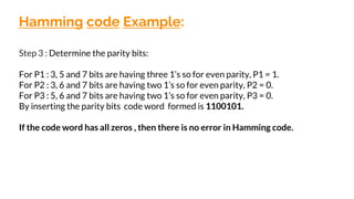
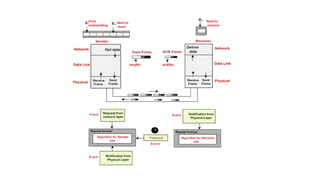
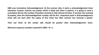
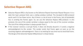
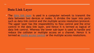
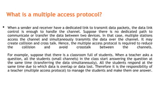
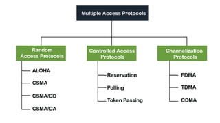
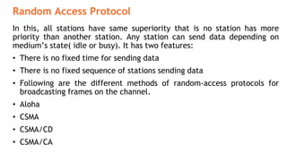
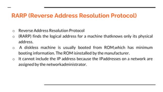
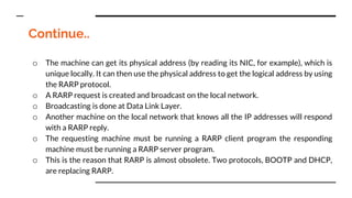
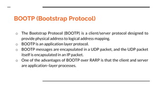
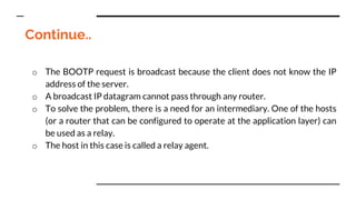
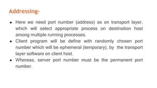
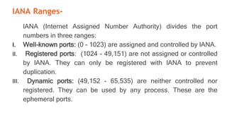
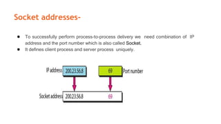
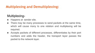
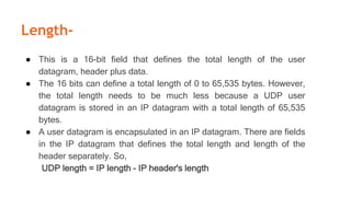
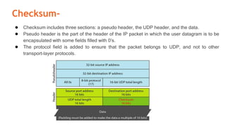
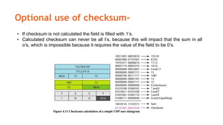
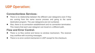
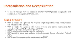
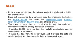
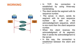
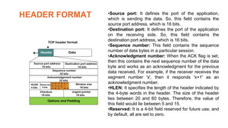
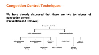
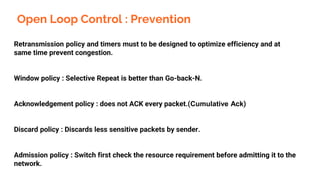
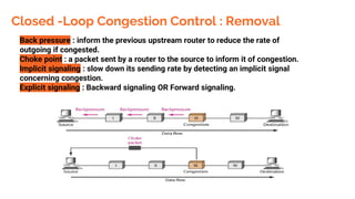
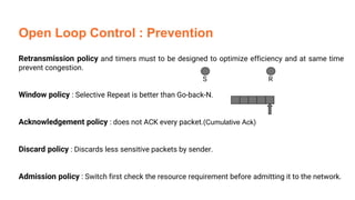
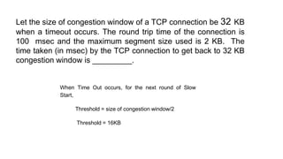
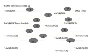
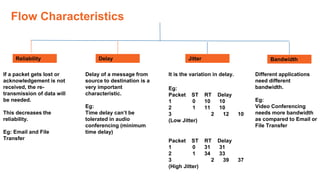
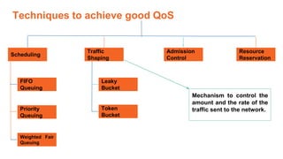
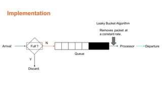
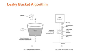
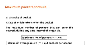
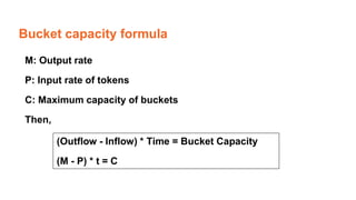
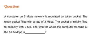
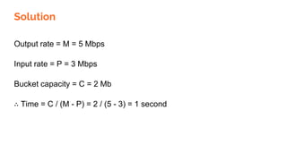
This document provides an overview of the topics that will be covered in the CS 352 Computer Networks course. The course is taught by Ms. Diksha Goyal and Unit 1 will cover OSI and TCP/IP models, network topologies, networking types, transmission media, networking devices, WLAN, and multiplexing. It then provides detailed descriptions of data representation, OSI layers including physical, data link, network, transport, session, presentation, and application layers. It also describes TCP/IP layers including network access, internet, and host-to-host layers.


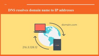
![A group composed of Jon Postel, Paul Mockapetris, Craig Partridge, and
others [Harvard University] met the need when they published RFC 882
in 1984 which resulted in the creation of the distributed naming
system known as the DNS.
Using Distributed DNS since 1984](https://image.slidesharecdn.com/cs-324computernetworks-240126052827-f3b89eca/85/CS-324-Computer-Networks-pdf-370-320.jpg)