Downloaded 31 times
![International Journal of Engineering Research and Development
e-ISSN: 2278-067X, p-ISSN: 2278-800X, www.ijerd.com
Volume 6, Issue 2 (March 2013), PP.22-27
Increasing the Power Quality for Grid Connected Wind
Energy System Using Facts
Gracr Priyanka J1, Alex David S2, Anitha J3
1
Assistant Professor, Dr. G. U. Pope College of Engineering, Sawyerpuram.
2
Assistant Professor, Sree Sastha College of Engineering, Chennai.
3
ME Power System, Anna University Regional Centre, Coimbatore.
Abstract:- Power quality is affected by injection of the wind power into an electric grid. Generated
power from wind energy system is always fluctuating due to the fluctuations in the wind. To
mitigate the power quality issues STATic COMpensator (STATCOM) is connected at a point of
common coupling with a battery energy storage system (BESS) is proposed here. Under fluctuating
wind power the battery energy storage is integrated to sustain the real power source. The system is
simulated using MATLAB/SIMULINK in power system block set.
Keywords:- Power Quality, Wind Generating System (WGS), STATCOM, BESS
I. INTRODUCTION
The demand of electricity increased dramatically nowadays, to satisfy this electrical demand, it is
needed to utilize the renewable energy resources like wind, biomass, hydro, co-generation, etc, The renewable
energy like wind need to integrate with power system to reduce the impact on environment. The integration of
wind energy into existing power system presents a technical challenges and that requires consideration of
voltage regulation, stability, power quality problems. The serious issue in wind turbine is power quality. The
rapid change in wind makes the behavior of wind generator quite different from conventional generator. In
recent years there has been extensive growth and quick development in the exploitation of wind energy. The
individual units can be of large capacity up to 2 MW, feeding into distribution network, particularly with
customers connected in close proximity [8].
Large voltage fluctuations occur when all the fluctuations in the wind speed are transmitted as
fluctuations in the mechanical torque in the fixed-speed wind turbine operation. During normal operation
continuous variable output power was produced by wind turbine. The effect of turbulence, wind shear, and
tower-shadow and control system in the power system causes the variations in power. Such fluctuations are
needed to be managed by the network. The power quality issues can be viewed with respect to the wind
generation, transmission and distribution network, such as voltage sag, swells, flickers, harmonics etc. Induction
generator which is connected directly to the grid system is the simple method of running a wind generating
system. Cost effectiveness and robustness are the advantages of induction generator.
A proper control scheme in wind energy generation system is required under normal operating
condition to allow the proper control over the active power production. Power quality can be improved by the
STATCOM-based control technology. Objectives are proposed by STATCOM control scheme for grid
connected wind energy generation for power quality improvement are, unity power factor at the source side,
reactive power support only from STATCOM to wind Generator and Load, simple bang-bang controller for
STATCOM to achieve fast dynamic response. At the Point of Common Coupling (PCC) high performance
steady state and transient voltage control have been achieved by the Shunt Flexible AC Transmission System
(FACTS) devices, such as the Static Var Compensator (SVC) and the Static Synchronous Compensator
(STATCOM) [8]. In [9] applications of SVC or a STATCOM to fixed-speed wind turbines equipped with
induction generators have been reported for steady state voltage regulation, and in [1] for short-term transient
voltage stability. The remaining of this paper has been organized as: Section II introduces the wind turbine
model. Section III introduces STATCOM controller section IV describes Grid coordination rules. Section V
gives overall system design. Control Scheme is described in section VI. Simulation results are presented in
Section VII. Finally the work is concluded with future enhancement.
II. WIND TURBINE MODEL
The aerodynamic model of a wind turbine can be characterized by the well-known CP-λ-β curves. CP
is called power coefficient, which is a function of both tip-speed-ratio λ and the blade pitch angle β. The tip-
speed-ratio λ is defined by Λ= ωt R/vw (1)
22](https://image.slidesharecdn.com/d06022227-130323020605-phpapp02/85/journal-publishing-how-to-publish-research-paper-Call-For-research-paper-international-journal-publishing-a-paper-IJERD-journal-of-science-and-technology-how-to-get-a-research-paper-published-publishing-a-paper-publishing-of-journal-publishing-o-1-320.jpg)
![International Journal of Engineering Research and Development
e-ISSN: 2278-067X, p-ISSN: 2278-800X, www.ijerd.com
Volume 6, Issue 2 (March 2013), PP.22-27
Increasing the Power Quality for Grid Connected Wind
Energy System Using Facts
Gracr Priyanka J1, Alex David S2, Anitha J3
1
Assistant Professor, Dr. G. U. Pope College of Engineering, Sawyerpuram.
2
Assistant Professor, Sree Sastha College of Engineering, Chennai.
3
ME Power System, Anna University Regional Centre, Coimbatore.
Abstract:- Power quality is affected by injection of the wind power into an electric grid. Generated
power from wind energy system is always fluctuating due to the fluctuations in the wind. To
mitigate the power quality issues STATic COMpensator (STATCOM) is connected at a point of
common coupling with a battery energy storage system (BESS) is proposed here. Under fluctuating
wind power the battery energy storage is integrated to sustain the real power source. The system is
simulated using MATLAB/SIMULINK in power system block set.
Keywords:- Power Quality, Wind Generating System (WGS), STATCOM, BESS
I. INTRODUCTION
The demand of electricity increased dramatically nowadays, to satisfy this electrical demand, it is
needed to utilize the renewable energy resources like wind, biomass, hydro, co-generation, etc, The renewable
energy like wind need to integrate with power system to reduce the impact on environment. The integration of
wind energy into existing power system presents a technical challenges and that requires consideration of
voltage regulation, stability, power quality problems. The serious issue in wind turbine is power quality. The
rapid change in wind makes the behavior of wind generator quite different from conventional generator. In
recent years there has been extensive growth and quick development in the exploitation of wind energy. The
individual units can be of large capacity up to 2 MW, feeding into distribution network, particularly with
customers connected in close proximity [8].
Large voltage fluctuations occur when all the fluctuations in the wind speed are transmitted as
fluctuations in the mechanical torque in the fixed-speed wind turbine operation. During normal operation
continuous variable output power was produced by wind turbine. The effect of turbulence, wind shear, and
tower-shadow and control system in the power system causes the variations in power. Such fluctuations are
needed to be managed by the network. The power quality issues can be viewed with respect to the wind
generation, transmission and distribution network, such as voltage sag, swells, flickers, harmonics etc. Induction
generator which is connected directly to the grid system is the simple method of running a wind generating
system. Cost effectiveness and robustness are the advantages of induction generator.
A proper control scheme in wind energy generation system is required under normal operating
condition to allow the proper control over the active power production. Power quality can be improved by the
STATCOM-based control technology. Objectives are proposed by STATCOM control scheme for grid
connected wind energy generation for power quality improvement are, unity power factor at the source side,
reactive power support only from STATCOM to wind Generator and Load, simple bang-bang controller for
STATCOM to achieve fast dynamic response. At the Point of Common Coupling (PCC) high performance
steady state and transient voltage control have been achieved by the Shunt Flexible AC Transmission System
(FACTS) devices, such as the Static Var Compensator (SVC) and the Static Synchronous Compensator
(STATCOM) [8]. In [9] applications of SVC or a STATCOM to fixed-speed wind turbines equipped with
induction generators have been reported for steady state voltage regulation, and in [1] for short-term transient
voltage stability. The remaining of this paper has been organized as: Section II introduces the wind turbine
model. Section III introduces STATCOM controller section IV describes Grid coordination rules. Section V
gives overall system design. Control Scheme is described in section VI. Simulation results are presented in
Section VII. Finally the work is concluded with future enhancement.
II. WIND TURBINE MODEL
The aerodynamic model of a wind turbine can be characterized by the well-known CP-λ-β curves. CP
is called power coefficient, which is a function of both tip-speed-ratio λ and the blade pitch angle β. The tip-
speed-ratio λ is defined by Λ= ωt R/vw (1)
22](https://image.slidesharecdn.com/d06022227-130323020605-phpapp02/75/journal-publishing-how-to-publish-research-paper-Call-For-research-paper-international-journal-publishing-a-paper-IJERD-journal-of-science-and-technology-how-to-get-a-research-paper-published-publishing-a-paper-publishing-of-journal-publishing-o-1-2048.jpg)
![Increasing The Power Quality For Grid Connected Wind Energy System Using Facts
Where R is the blade length in m, ωt is the wind turbine rotor speed in rad/s, and vw is the wind speed
in m/s. The CP-λ-β curves depend on the blade design and are given by the wind turbine manufacturer. Given
the power coefficient CP, the mechanical power extracted by the turbine from the wind, is calculated by
Pm = ½ ρAr Vw3Cp(λ,β) (2)
Where ρ is the air density in kg/m3; Ar = πR2 is the area in m2 swept by the rotor blades. At a specific
wind speed, there is a unique value of ωt, to achieve the maximum power coefficient CP and thereby extract the
maximum mechanical (wind) power. If the wind speed is below the rated (maximum) value, the wind turbine
operates in the variable speed mode, and the rotational speed is adjusted such that the maximum value of CP is
achieved. In this operating mode, the wind turbine pitch control is deactivated and the pitch angle β is
fixed at 0○. If the wind speed is above the rated value, the rotor speed can no longer be controlled
within the limits by increasing the generated power, as this would lead to overloading of the generator
and/or the converter. In this situation, the pitch control is activated to increase the wind turbine pitch angle
to reduce the mechanical power extracted from wind[1].
III. STATCOM MODEL
Shunt connected FACTS device STATCOM also known as an advanced static VAR compensator. At
the fundamental frequency, with rapidly controllable amplitude and phase angle it generates a set of balanced
three-phase sinusoidal voltages. Voltage support is a typical application of STATCOM. STATCOM is used for
voltage support. In this paper, the STATCOM is modeled as a IGBT PWM converter with a dc-link capacitor.
The objective of the STATCOM is to regulate the voltage at the PCC rapidly in the desired range and
keep its dc-link voltage constant. It can enhance the capability of the wind turbine to ride through
transient disturbances in the grid.
IV. GRID COORDINATION RULE
Grid code for the inter-connection of the wind plants to the utility system was adopted in the United
States by the American Wind Energy Association (AWEA). Distribution level was first focused in grid code,
after the blackout in the United State in August 2003. The rules for realization of grid operation of wind
generating system at the distribution net-work are defined as-per IEC-61400-21. The grid quality characteristics
and limits are given for references that the customer and the utility grid may expect. According to Energy-
Economic Law, the operator of transmission grid is responsible for the organization and operation of
interconnected system.
1. Voltage Rise (u): The voltage rise at the point of common coupling can be approximated as a function of
maximum apparent power of the turbine, the grid impedances R and X at the point of common coupling and the
phase angle [2], given in (3)
𝜟𝖚 = (3)
where, 𝜟𝖚 -voltage rise, smax —max. apparent power, Φ—phase difference, U—nominal voltage of grid.
The Limiting voltage rise value is <2 %
2) Voltage Dips (d): The voltage dips is due to start up of wind turbine and it causes a sudden reduction of
voltage. It is the relative % voltage change due to switching operation of wind turbine. The decrease of nominal
voltage change is given in (4).
D = Ku sn/sk (4)
Where d is relative voltage change, sn is rated apparent power, sk is short circuit apparent power, and Ku is
sudden voltage reduction factor. The acceptable voltage dips limiting value is <3%.
3) Flicker: The measurements are made for maximum number of specified switching operation of wind turbine
with 10-min period and 2-h period are specified, as given in (5)
P𝖚 = c (ψk ) sn/sk (5)
Where P𝖚 - Long term flicker. c (ψk ) - Flicker coefficient . The Limiting Value for flicker coefficient is about ≤
0.4, for average time of 2 h [6].
4) Harmonics: The harmonic distortion is assessed for variable speed turbine with a electronic power converter
at the point of common connection. The total harmonic voltage distortion of voltage is given as in (6)
VTHD = 100 (6)
Where Vn is the nth harmonic voltage and V1 is the fundamental frequency (50) Hz.
The THD limit for 132 KV is < 3%. THD of current ITHD is given as in (7)
23](https://image.slidesharecdn.com/d06022227-130323020605-phpapp02/85/journal-publishing-how-to-publish-research-paper-Call-For-research-paper-international-journal-publishing-a-paper-IJERD-journal-of-science-and-technology-how-to-get-a-research-paper-published-publishing-a-paper-publishing-of-journal-publishing-o-2-320.jpg)
![Increasing The Power Quality For Grid Connected Wind Energy System Using Facts
ITHD = 100 (7)
where In is the nth harmonic current and I1is the fundamental frequency (50) Hz. The THD of current and
limit for 132 KV is <2.5%.
5) Grid Frequency: The grid frequency in India is specified in the range of 47.5–51.5 Hz, for wind farm
connection.
V. GRID CONNECTED SYSTEM FOR POWER QUALITY IMPROVEMENT
The current is inject into the grid in such a way that the source current are harmonic free and their
phase-angle with respect to source voltage has a desired value by the STATCOM based current control voltage
source inverter.
The reactive part and harmonic part of the load and induction generator current is cancelled out by
injected current this lead to the power factor and the power quality improvement. The grid voltages are sensed
and were synchronized in generating the current command for the inverter to accomplish above goals. Fig. 1.
shows the proposed grid connected system and it is implemented for power quality improvement at the point of
common coupling (PCC). Wind energy generation system and battery energy storage system with STATCOM
were included in grid connected system.
Fig. 1. Grid connected system for power quality improvement.
A.WIND ENERGY GENERATING SYSTEMS
Wind generations are based on constant speed topologies with pitch control turbine. Due to the
simplicity of induction generator is used in the proposed scheme, a separate field circuit not needed, constant
and variable loads can accepted, and has natural protection against short circuit. The available power of wind
energy system is shown in (8)
(8)
Where ρ(kg/m) is the air density and A(m2) is the area swept out by turbine blade, Vwind is the wind
speed in mtr/s. It extract a fraction of power in wind because it impossible to extract all kinetic energy of wind,
called power coefficient Cp of the wind turbine.
(9)
Where Cp is the power coefficient, depends on type and operating condition of wind turbine. This
coefficient can be express as a function of tip speed ratio γ and θ pitch angle. The mechanical power produce by
wind turbine is given in (10)
(10)
Where R is the radius of the blade (m).
B. BESS- STATCOM
For voltage regulations the battery energy storage system (BSSS) is used as an energy storage element.
The BESS will naturally maintain dc capacitor voltage constant and is best suited in STATCOM since it rapidly
injects or absorbed reactive power to stabilize the grid system. It quickly controls the distribution and
transmission system. Power fluctuation leveled by BESS by charging and discharging operation when power
fluctuation occurs in the system. The battery is connected in parallel to the dc capacitor of STATCOM [3]–[4].
The STATCOM is a three-phase voltage source inverter having the capacitance on its DC link and connected at
24](https://image.slidesharecdn.com/d06022227-130323020605-phpapp02/85/journal-publishing-how-to-publish-research-paper-Call-For-research-paper-international-journal-publishing-a-paper-IJERD-journal-of-science-and-technology-how-to-get-a-research-paper-published-publishing-a-paper-publishing-of-journal-publishing-o-3-320.jpg)
![Increasing The Power Quality For Grid Connected Wind Energy System Using Facts
the point of common coupling. The STATCOM injects a compensating current of variable magnitude and
frequency component at the bus of common coupling.
C. SYSTEM OPERATION
The shunt connected STATCOM with battery energy storage is connected with the interface of the
induction generator and non-linear load at the PCC in the grid system. According to the controlled strategy the
STATCOM compensator output is varied, so as the power quality norms maintained in the grid system. The
control scheme that defines the functional operation of the STATCOM compensator in the power system
included in the current control strategy. A single STATCOM using insulated gate bipolar transistor is proposed
to have a reactive power support, to the induction generator and to the nonlinear load in the grid system. Fig.2.
shows system operational scheme.
Fig. 2. System operational scheme in grid system.
VI. CONTROL SCHEME
Bang-Bang controller used to inject the current in to grid in the control scheme approach. The
controller uses a hysteresis current controlled technique. The control system variable is kept between boundaries
of hysteresis area and gives correct switching signals for STATCOM operation using this technique. The control
system scheme for generating the switching signals to the STATCOM is shown in Fig. 3.The measurements of
several variables needed for control algorithm, such as three-phase source current, DC voltage, inverter current
with the help of sensor. An input of reference current is received by current control block, and to activate the
operation of STATCOM in current control mode actual current are subtracted [5] [7]. In three-phase balance
system, at the sampling frequency from the source phase voltage (Vsa, Vsb, Vsc), the RMS voltage source
amplitude is calculated and is expressed, as sample template, sampled peak voltage, as in (11)
Fig. 3. Control system scheme
(11)
The in-phase unit vectors are obtained from AC source—phase voltage and the RMS value of unit
vector (Usa, Usb, Usc) as shown in bellow (12)
(12)
The in-phase generated reference currents are derived using in-phase unit voltage template as bellow (13)
(13)
Where I= is proportional to magnitude of filtered source voltage for respective phases. This ensures that the
source current is controlled to be sinusoidal. In the current control scheme the Bang-Bang current controller
implemented. The reference current is generated and actual current are detected by current sensors and are
25](https://image.slidesharecdn.com/d06022227-130323020605-phpapp02/85/journal-publishing-how-to-publish-research-paper-Call-For-research-paper-international-journal-publishing-a-paper-IJERD-journal-of-science-and-technology-how-to-get-a-research-paper-published-publishing-a-paper-publishing-of-journal-publishing-o-4-320.jpg)
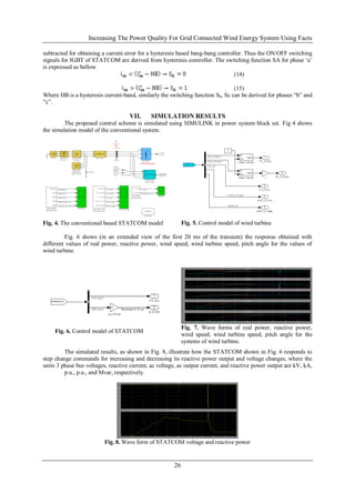
![Increasing The Power Quality For Grid Connected Wind Energy System Using Facts
Fig. 9. Wave form of PCC or Grid parameters with STATCOM control
VIII. CONCLUSION
The power quality improvement in grid connected wind generating system and with nonlinear load was
achieved with STATCOM-based control scheme. Wind turbine model, STATCOM model and Grid
coordination rules were presented. The operation of the control system developed for the STATCOM-BESS in
MATLAB/SIMULINK for maintaining the power quality is simulated. The STATCOM based controller not
only control current from stator also improves stability, it can mitigate both current and voltage
harmonics occurring in the system because of natural phenomenon or due to external sources.
REFERENCES
[1]. A. Sannino, ―Global power systems for sustainable development,‖ in IEEE General Meeting, Denver,
CO, Jun. 2004.
[2]. C. Han, A. Q. Huang, M. Baran, S. Bhattacharya, and W. Litzenberger, ―STATCOM impact study on
the integration of a large wind farm into a weak loop power system,‖ IEEE Trans. Energy Conv., vol.
23, no. 1, pp. 226–232, Mar. 2008.
[3]. D. L. Yao, S. S. Choi, K. J. Tseng, and T. T. Lie, ―A statistical approach to the design of a dispatchable
wind power—Battery energy storage system,‖ IEEE Trans. Energy Conv., vol. 24, no. 4, Dec. 2009.
[4]. T. Kinjo and T. Senjyu, ―Output leveling of renewable energy by electric double layer capacitor
applied for energy storage system,‖ IEEE Trans. Energy Conv., vol. 21, no.1, Mar. 2006.
[5]. Fu. S. Pai and S.-I. Hung, ―Design and operation of power converter for microturbine powered
distributed generator with capacity expansion capability,‖ IEEE Trans. Energy Conv., vol. 3, no. 1, pp.
110–116, Mar. 2008
[6]. J. J. Gutierrez, J. Ruiz, L. Leturiondo, and A. Lazkano, ―Flicker measurement system for wind turbine
certification,‖ IEEE Trans. Instrum. Meas., vol. 58, no. 2, pp. 375– 382, Feb. 2009.
[7]. M. I. Milands, E. R. Cadavai, and F. B. Gonzalez, ―Comparison of control strategies for shunt active
power filters in three phase four wire system,‖ IEEE Trans. Power Electron., vol. 22, no. 1, pp. 229–
236, Jan. 2007.
[8]. M. Tsili and S. Papathanassiou, ―A review of grid code technology requirements for wind
turbine,‖ Proc. IET Renew. Power gen., vol. 3, pp. 308–332, 2009.
[9]. S. Heier, Grid Integration of Wind Energy Conversions. Hoboken, NJ: Wiley, 2007, pp. 256–259.
27](https://image.slidesharecdn.com/d06022227-130323020605-phpapp02/85/journal-publishing-how-to-publish-research-paper-Call-For-research-paper-international-journal-publishing-a-paper-IJERD-journal-of-science-and-technology-how-to-get-a-research-paper-published-publishing-a-paper-publishing-of-journal-publishing-o-6-320.jpg)

The document discusses improving power quality in grid-connected wind energy systems using a Static Compensator (STATCOM) integrated with Battery Energy Storage Systems (BESS). It outlines how fluctuations in wind energy generation can lead to power quality issues and describes a control scheme for mitigating these challenges through simulations in MATLAB/Simulink. Additionally, it covers the operational mechanisms of wind turbines, STATCOM, and grid coordination rules essential for maintaining power quality.