SlideShare a Scribd company logo
1 of 10
Download to read offline
International Journal of Engineering Research and Development
e-ISSN: 2278-067X, p-ISSN: 2278-800X, www.ijerd.com
Volume 11, Issue 09 (September 2015), PP.62-71
62
Router 1X3 – RTL Design and Verification
Nidhi Gopal1
Abstract:- Routing is the process of moving a packet of data from source to destination and enables messages
to pass from one computer to another and eventually reach the target machine. A router is a networking device
that forwards data packets between computer networks. It is connected to two or more data lines from different
networks (as opposed to a network switch, which connects data lines from one single network). This paper,
mainly emphasizes upon the study of router device, it‟s top level architecture, and how various sub-modules of
router i.e. Register, FIFO, FSM and Synchronizer are synthesized, and simulated and finally connected to its top
module.
Keywords:- Routing, Router, Data Packets, Verilog, Xilinx ISE, Questasim
I. INTRODUCTION
A router is a networking device that forwards data packets between computer networks. A router is
connected to two or more data lines from different networks (as opposed to a network switch, which connects
data lines from one single network). When a data packet comes in on one of the lines, the router reads the
address information in the packet to determine its ultimate destination. Then, using information in its routing
table or routing policy, it directs the packet to the next network on its journey. This creates an
overlay internetwork. Routers perform the "traffic directing" functions on the Internet. A data packet is typically
forwarded from one router to another through the networks that constitute the internetwork until it reaches its
destination node.
Fig 1. Router Device
II. THEORETICAL BACKGROUND
A router is a device that forwards data packets along networks. It is connected to at least two networks,
commonly two LANs or WANs or a LAN and its ISP's network and is located at gateways, the places where
two or more networks connect. It is an OSI layer 3 routing device. It drives an incoming packet to an output
channel based on the address fields contained in the packet header. Routers use headers and forwarding tables to
determine the best path for forwarding the packets, and they use protocols to communicate with each other and
configure the best route between any two hosts.
Router 1X3 – RTL Design and Verification
63
Figure below, shows top level architecture of router, which include components like FIFO, Register,
synchronizer, FSM and input and output signals between them.
Diagrammatic Comparison between OSI Reference Model and TCP/IP Reference Model
1. Router packet:
Packet format: the packet consists of 3 parts: Header, payload and parity each of 8 bit width and the length of
the payload can be extended between 3 between 1 byte to 63 byte.
Router 1X3 – RTL Design and Verification
64
 Header: Packet header contain two fields DA and length.
 DA: destination address of the packet is of 2 bits. The router drives the packet to the respective ports
based on this destination address of the packets.
Each output port has 2-bit unique port address. If the destination address of the packet matches the port address,
then router drives the packet to the output port. The address „3‟ is invalid.
 Length: length of the data is of 6-bits. It specifies the number of the number of the data bytes. A packet
can have a minimum data size of 1 byte and a maximum size of 63 bytes.
If length =1, it means data length is 1 byte
If length =2, it means data length is 2 bytes
If length =63, it means data length is 63 bytes
 Payload: payload is the data information. Data should be in terms of the bytes.
 Parity: This field contains the security check of the packet. It is calculated as bitwise parity over the
header and payload bytes of the packet as mentioned below.
2. Router Input Protocol:
The characteristics of the DUT input protocols are as follows:
 Testbench Notes: All input signals are active high except low reset and are synchronized to the falling edge
of the clock. This is because the DUT router is sensitive to the rising edge of the clock. Therefore, in the
testbench, driving input signals on the falling edge ensures setup and hold time. But in the system
Verilog/UVM based testbench, clocking block can be used to drive the signals on the positive edge of the
clock itself and thus avoids metastability.
 The packet_valid signal is asserted on the same clock edge when the header byte driven onto the input data
bus.
 Since the header byte contains the address, this the router to which output channel the packet should be
routed to (data_out_0, data_out_1, data_out_2).
 Each subsequent byte of payload after header byte should be driven on the input data bus for every new
falling edge of the clock.
Router 1X3 – RTL Design and Verification
65
 After the last payload byte has been driven, on the next falling edge of the clock, the packet_valid signal
must be de-asserted, and the packet parity should be driven. This signals packet completion.
 The testbench shouldn`t drive any byte when busy signal is detected instead it should hold the last driven
values.
 The `busy` signal when asserted drops any incoming byte of the data.
 The “err” signal is asserted when a packet parity mismatch is detected.
3. Router Output Protocol
The characteristics of the output protocol are as follows:
 Test bench Note: All output signals are active high and are synchronized to the rising edge of the clock.
 Each output port data_out_X (data_out_0, data_out_1, data_out_2) is internally buffered by a FIFO of size
16X9.
 The router asserts the vld_out_X (vld_out_0, vld_out_!, vld_out_2) signal when valid data appears on the
vld_out_X(data_out_0,data_out_1,data_out_2) output bus. This is a signal to the receiver‟s client which
indicates the data is available on a particular output data bus.
 The packet receiver will then wait until it has enough space to hold the bytes of the packet and then respond
with the assertion of the read_enb_X(read_enb_0.read_enb_1,read_enb_2) signal.
 The read_enb_X(read_enb_0,read_enb_`1 or read_enb_2) input signal can be asserted on the falling clock
edge in which data are read from the data_out_X(data_out_0,data_out_1,data_out_2)bus.
 The read_enb_X(read_enb_0,read_out_1 or read_out_2) must be asserted within 30 clock cycles of the
vld_out_X(vld_out_0,vld_out_1,vld_out_2) being asserted else time-out occurs, which resets the FIFO.
 The data_out_X (data_out_0,data_out_1 or data_out_2) bus will be tri-stated(high Z) during a scenario
when a packet‟s header byte is lost due to time-out condition .
4. Router- Top Level block
The top level architecture of router is shown in the figure. The router module consists of FSM,
REGISTER, SYNCHRONIZER, FIFO_0, FIFO_1, FIFO_2.
During the course of the designing and implementing the whole module, we design each sub-module one by one
individually using RTL coding in Verilog and then from the top we will instantiate all sub-module using
structural style of modeling and using some constructs of advance Verilog also.
5. Router : FIFO
Functionality
There are 3 FIFOs used in the router design. Each FIFO is of 9 bits wide and 16 bit bytes depth. The
FIFO works on the system clock and is reset with a synchronizer active low reset.The FIFO is also internally
reset by an internal reset signal soft_reset. Soft_reset is an active high signal which is generated by the
SYNCHRONIZER block during time out state of the ROUTER.
If resetn is low then full=0, empty=1 and data_out=0.
Router 1X3 – RTL Design and Verification
66
The FIFO m/m size is 16X9. The extra bit in the data width is appended in order to detect the header byte.
Lfd_state detects the header byte of a packet.
The 9th
bit is 1 for header byte and 0 for the remaining bytes.
Write Operation:
 Signal data_in is sampled at the rising edge of the edge of the clock when write_enb is high.
 Write operation only takes place when FIFO is not full in order to avoid over_run condition.
Read operation:
 The data is read from data_out at rising edge of the clock, when read_enb is high.
 Read operation only takes place when the FIFO is not empty in order to avoid under run condition.
 During the read operation when a header byte is read, an internal counter is loaded with the payload
length of the packet plus „1‟ (parity byte) and starts decrementing every clock till it reached 0. The
counter holds 0 till it is reloaded back with a new packet payload length.
 During the time out condition, full=0, empty=1.
 data out is driven to HIGH impedance state under 2 scenarios:
 When the fifo m/m is read completely (header+payload+parity).
 Under the time out condition of the Router.
 Full- FIFO status which indicates that all the locations inside FIFO have been written.
 Empty- FIFO status which indicates that all the locations of the FIFO have been read and made empty.
 Read and write operation can be done simultaneously.
6. ROUTER : SYNCHRONIZER
Functionality:
This module provides synchronization between router FSM and router FIFO modules. It provides faithful
communication between the single input port and three output ports.
 detect_add and data_in signals are used to select a FIFO till a packet routing is over for the selected
FIFO.
 Signal fifo_full signal is asserted based on full_status of fifo_0 or FIFO_1 or FIFO_2.
 If data_in =2‟b00 then fifo_full=full_0
 If data_in=2‟b01 then fifo_full=full_1
 If data_in=2‟b10 then fifo_full=full_2 else fifo_full=0
 The signal vld_out_x signal is generated based on empty status of the FIFO as shown below :
 vld_out_0=~empty_0
 vld_out_1=~empty_1
 vld_out_2=~empty_2
 The write_enb_reg signal is used to generate write_enb signal for the write operation of the selected
FIFO.
 There are 3 internal reset signals (soft_reset_0, soft_reset_1, soft_reset_2) for each of the FIFO
respectively. The respective internal reset signals goes high if read_enb_X
(read_enb_0,read_out_1,read_out_2) is not asserted within 30 clock cycles of the
vld_out_X(vld_out_0,vld_out_1 or vld_out_2) being asserted respectively.
Router 1X3 – RTL Design and Verification
67
7. ROUTER: FSM
STATE-DECODE_ADDRESS
 This is the initial reset state.
 Signal detect_add is asserted in this state which is used to detect an incoming packet. It is also used to
latch the first byte as a header byte.
STATE-LOAD_FIRST_DATA
 Signal lfd_state is asserted in this state which is used to load the first data byte to the FIFO.
 Signal busy is also asserted in this state so that header byte that is already latched doesn‟t update to a
new value for the current packet.
 This state is changed to LAOD_DATA state unconditionally in the next clock cycle.
STATE-LOAD_DATA
 In this state the signal ld_state is asserted which is used to load the payload data to the FIFO.
 Signal busy is de asserted in this state, so that ROUTER can receive the new data from input source
every clock cycle,
 Signal write_enb_reg is asserted in this state in order to write the Packet information
(Header+Payload+Parity) to the selected FIFO.
 This state transits to LAOD_PARITY state when pkt_valid goes low and to FIFO_FULL_STATE
when FIFO is full.
STATE-LOAD_PARITY
 In this state the last byte is latched which is the parity byte.
 It goes unconditionally to the state CHECK_PARITY_ERROR.
 Signal busy is asserted so that ROUTER doesn‟t accepts any new data.
 write_enb_reg is made high for latching the parity byte to FIFO.
STATE-FIFO_FULL_STATE
 Busy signal is made high and write_enb_reg signal is made low.
 Signal full_state is asserted which detects the FIFO full state.
STATE-LOAD_AFTER_FULL
 In this state laf_state signal is asserted which is used to latch the data after FIFO_FULL_STATE.
 Signal busy & write_enb_reg is asserted.
 It checks for parity_done signal and if it is high, shows that LOAD_PARITY state has been detected
and it goes to the state DECODE_ADDRESS.
 If low_packet_valid is high it goes to LOAD_PARITY state otherwise it goes back to the
LOAD_DATA state.
STATE-WAIT_TILL_EMPTY
 Busy signal is made high and write_enb_reg signal is made low.
STATE-CHECK_PARITY_ERROR
 In this state rst_int_reg signal is generated, which is used to reset low_packet_valid signal.
 This state changes to DECODE_ADDRESS when FIFO is not full and to FIFO_FULL_STATE when
FIFO is full.
 Busy is asserted in this state.
Router 1X3 – RTL Design and Verification
68
8. ROUTER: Register
Functionality:
This module implements 4 internal registers in order to hold a header byte, FIFO full state byte, internal parity
and packet parity byte. All the registers in this module are latched on the rising edge of the clock.
 If resetn is low then the signals (dout,err,parity_done and low_pkt_valid) are low.
 The signal parity_done is high under the following conditions:
 When signal ld_state is high and signals (fifo_full and pkt_valid) are low.
 When signals laf_state and low_pkt_valid both are high and the previous value of parity_done is low.
 rst_int_reg signal is used to reset low_pkt_valid signal.
 detect_add signal is used to reset parity_done signal.
 Signal low_pkt_valid is high when ld_state is high and pkt_valid is low. Low_packet_valid shows
that pkt_valid for current state has been deasserted.
 First data byte i.e., header is latched inside an internal register when detect_add and pkt_valid signals
are high. This data is latched to the output dout when lfd_state goes high.
 Then signal data_in i.e. Payload is latched to dout if ld_state signal is high and fifo_full is low.
 Signal data_in is latched to an internal register when ld_state and fifo_full are high. This data is
latched to output dout when laf_state goes high.
 Full_state is used to calculate internal parity.
 Another internal register is used to store internal parity for parity matching. Internal parity is calculated
using the bit-wise xor operation between header byte, payload byte and previous parity values as shown
below:
parity_reg=parity_reg_previous^header_byte ---- t1 clock cycle
Last payload byte
 The err is calculated only after packet parity is loaded and goes high if the packet parity doesn‟t match
with the internal parity.
III. SIMULATION RESULTS
Following components of router were synthesized and simulated, using Xilinx ISE software. And
Simulation results were observed. Following are the results obtained:
Router 1X3 – RTL Design and Verification
69
Figure: Fifo output
Figure: Fsm output
Router 1X3 – RTL Design and Verification
70
Figure: Synchronizer output
Figure: Top output
IV. CONCLUSION
The Router1X3 is designed and verified successfully. Many coding bugs are debugged during the
verification.
Scenarios like packets with payload length
 8 byte
 14 byte
 16 byte
 17 byte
 FIFO full state(observing busy signal)
 good packet
 packet which is never read
Router 1X3 – RTL Design and Verification
71
 Simultaneous read write operation
 Bad packet/corrupt packet
were driven from the testbench to determine the robustness of the design. And it was working seamlessly as
shown by the coverage report produced by Questasim with 100% FSM state coverage, 81.81% FSM transition
coverage, 96.42% toggle coverage, 92.40% statement coverage.
Figure: Coverage Summary: By structure, by type
Figure: Coverage report by instance
Figure: Coverage Report
ACKNOWLEDGEMENT
The author would like to thank Mrs. Susmita Nayak, and Mr. Putta Satish for their proper guidance,
continuous support and engagement in this research.
REFERENCES
[1]. Verilog HDL:- Samir Palnitkar
[2]. System Verilog:- Chris Spear
[3]. The ASIC Website: www.asicworld.com
[4]. www.google.com/fifo-theory-verilog
[5]. www.wikipedia.com

More Related Content

What's hot

VLSI Design Flow
VLSI Design FlowVLSI Design Flow
VLSI Design FlowA B Shinde
 
Verilog presentation final
Verilog presentation finalVerilog presentation final
Verilog presentation finalAnkur Gupta
 
Jtag presentation
Jtag presentationJtag presentation
Jtag presentationklinetik
 
Spartan-II FPGA (xc2s30)
Spartan-II FPGA (xc2s30)Spartan-II FPGA (xc2s30)
Spartan-II FPGA (xc2s30)A B Shinde
 
AMBA 3 APB Protocol
AMBA 3 APB ProtocolAMBA 3 APB Protocol
AMBA 3 APB ProtocolSwetha GSM
 
Synopsys Fusion Compiler-Comprehensive RTL-to-GDSII Implementation System
Synopsys Fusion Compiler-Comprehensive RTL-to-GDSII Implementation SystemSynopsys Fusion Compiler-Comprehensive RTL-to-GDSII Implementation System
Synopsys Fusion Compiler-Comprehensive RTL-to-GDSII Implementation SystemMostafa Khamis
 
APB protocol v1.0
APB protocol v1.0APB protocol v1.0
APB protocol v1.0Azad Mishra
 
System verilog coverage
System verilog coverageSystem verilog coverage
System verilog coveragePushpa Yakkala
 
Clock divider by 3
Clock divider by 3Clock divider by 3
Clock divider by 3Ashok Reddy
 
Session 6 sv_randomization
Session 6 sv_randomizationSession 6 sv_randomization
Session 6 sv_randomizationNirav Desai
 
Spi master core verification
Spi master core verificationSpi master core verification
Spi master core verificationMaulik Suthar
 
ASIC Design Flow | Physical Design | VLSI
ASIC Design Flow | Physical Design | VLSI ASIC Design Flow | Physical Design | VLSI
ASIC Design Flow | Physical Design | VLSI Jayant Suthar
 
4.FPGA for dummies: Design Flow
4.FPGA for dummies: Design Flow4.FPGA for dummies: Design Flow
4.FPGA for dummies: Design FlowMaurizio Donna
 
Verilog Test Bench
Verilog Test BenchVerilog Test Bench
Verilog Test BenchDr.YNM
 

What's hot (20)

VLSI Design Flow
VLSI Design FlowVLSI Design Flow
VLSI Design Flow
 
Verilog HDL
Verilog HDLVerilog HDL
Verilog HDL
 
Verilog presentation final
Verilog presentation finalVerilog presentation final
Verilog presentation final
 
Jtag presentation
Jtag presentationJtag presentation
Jtag presentation
 
Fpga
FpgaFpga
Fpga
 
Spartan-II FPGA (xc2s30)
Spartan-II FPGA (xc2s30)Spartan-II FPGA (xc2s30)
Spartan-II FPGA (xc2s30)
 
AMBA 3 APB Protocol
AMBA 3 APB ProtocolAMBA 3 APB Protocol
AMBA 3 APB Protocol
 
Synopsys Fusion Compiler-Comprehensive RTL-to-GDSII Implementation System
Synopsys Fusion Compiler-Comprehensive RTL-to-GDSII Implementation SystemSynopsys Fusion Compiler-Comprehensive RTL-to-GDSII Implementation System
Synopsys Fusion Compiler-Comprehensive RTL-to-GDSII Implementation System
 
APB protocol v1.0
APB protocol v1.0APB protocol v1.0
APB protocol v1.0
 
I2 c protocol
I2 c protocolI2 c protocol
I2 c protocol
 
System verilog coverage
System verilog coverageSystem verilog coverage
System verilog coverage
 
axi protocol
axi protocolaxi protocol
axi protocol
 
Clock divider by 3
Clock divider by 3Clock divider by 3
Clock divider by 3
 
Session 6 sv_randomization
Session 6 sv_randomizationSession 6 sv_randomization
Session 6 sv_randomization
 
UART
UARTUART
UART
 
Spi master core verification
Spi master core verificationSpi master core verification
Spi master core verification
 
ASIC Design Flow | Physical Design | VLSI
ASIC Design Flow | Physical Design | VLSI ASIC Design Flow | Physical Design | VLSI
ASIC Design Flow | Physical Design | VLSI
 
4.FPGA for dummies: Design Flow
4.FPGA for dummies: Design Flow4.FPGA for dummies: Design Flow
4.FPGA for dummies: Design Flow
 
Verilog Test Bench
Verilog Test BenchVerilog Test Bench
Verilog Test Bench
 
Actel fpga
Actel fpgaActel fpga
Actel fpga
 

Viewers also liked

Influence of tensile behaviour of slab on the structural Behaviour of shear c...
Influence of tensile behaviour of slab on the structural Behaviour of shear c...Influence of tensile behaviour of slab on the structural Behaviour of shear c...
Influence of tensile behaviour of slab on the structural Behaviour of shear c...IJERD Editor
 
Gold prospecting using Remote Sensing ‘A case study of Sudan’
Gold prospecting using Remote Sensing ‘A case study of Sudan’Gold prospecting using Remote Sensing ‘A case study of Sudan’
Gold prospecting using Remote Sensing ‘A case study of Sudan’IJERD Editor
 
Reducing Corrosion Rate by Welding Design
Reducing Corrosion Rate by Welding DesignReducing Corrosion Rate by Welding Design
Reducing Corrosion Rate by Welding DesignIJERD Editor
 
SMICO Aggregate Vibratory Screeners
SMICO Aggregate Vibratory ScreenersSMICO Aggregate Vibratory Screeners
SMICO Aggregate Vibratory ScreenersSMICO MFG
 
Design Modification of Failure Mode Effect Analysis of Vibrating Feeder used ...
Design Modification of Failure Mode Effect Analysis of Vibrating Feeder used ...Design Modification of Failure Mode Effect Analysis of Vibrating Feeder used ...
Design Modification of Failure Mode Effect Analysis of Vibrating Feeder used ...ijsrd.com
 
A Novel Method for Prevention of Bandwidth Distributed Denial of Service Attacks
A Novel Method for Prevention of Bandwidth Distributed Denial of Service AttacksA Novel Method for Prevention of Bandwidth Distributed Denial of Service Attacks
A Novel Method for Prevention of Bandwidth Distributed Denial of Service AttacksIJERD Editor
 
Active Power Exchange in Distributed Power-Flow Controller (DPFC) At Third Ha...
Active Power Exchange in Distributed Power-Flow Controller (DPFC) At Third Ha...Active Power Exchange in Distributed Power-Flow Controller (DPFC) At Third Ha...
Active Power Exchange in Distributed Power-Flow Controller (DPFC) At Third Ha...IJERD Editor
 
MEMS MICROPHONE INTERFACE
MEMS MICROPHONE INTERFACEMEMS MICROPHONE INTERFACE
MEMS MICROPHONE INTERFACEIJERD Editor
 
Mitigation of Voltage Sag/Swell with Fuzzy Control Reduced Rating DVR
Mitigation of Voltage Sag/Swell with Fuzzy Control Reduced Rating DVRMitigation of Voltage Sag/Swell with Fuzzy Control Reduced Rating DVR
Mitigation of Voltage Sag/Swell with Fuzzy Control Reduced Rating DVRIJERD Editor
 
Vibrating feeder
Vibrating feederVibrating feeder
Vibrating feederJISHNU V
 
FEEDER & GRIZZLY STEEL STRUCTRE
FEEDER & GRIZZLY STEEL STRUCTREFEEDER & GRIZZLY STEEL STRUCTRE
FEEDER & GRIZZLY STEEL STRUCTRETokunbo Akinsara
 

Viewers also liked (15)

Influence of tensile behaviour of slab on the structural Behaviour of shear c...
Influence of tensile behaviour of slab on the structural Behaviour of shear c...Influence of tensile behaviour of slab on the structural Behaviour of shear c...
Influence of tensile behaviour of slab on the structural Behaviour of shear c...
 
Gold prospecting using Remote Sensing ‘A case study of Sudan’
Gold prospecting using Remote Sensing ‘A case study of Sudan’Gold prospecting using Remote Sensing ‘A case study of Sudan’
Gold prospecting using Remote Sensing ‘A case study of Sudan’
 
www.ijerd.com
www.ijerd.comwww.ijerd.com
www.ijerd.com
 
Vibrating feeder
Vibrating feederVibrating feeder
Vibrating feeder
 
Properl
ProperlProperl
Properl
 
www.ijerd.com
www.ijerd.comwww.ijerd.com
www.ijerd.com
 
Reducing Corrosion Rate by Welding Design
Reducing Corrosion Rate by Welding DesignReducing Corrosion Rate by Welding Design
Reducing Corrosion Rate by Welding Design
 
SMICO Aggregate Vibratory Screeners
SMICO Aggregate Vibratory ScreenersSMICO Aggregate Vibratory Screeners
SMICO Aggregate Vibratory Screeners
 
Design Modification of Failure Mode Effect Analysis of Vibrating Feeder used ...
Design Modification of Failure Mode Effect Analysis of Vibrating Feeder used ...Design Modification of Failure Mode Effect Analysis of Vibrating Feeder used ...
Design Modification of Failure Mode Effect Analysis of Vibrating Feeder used ...
 
A Novel Method for Prevention of Bandwidth Distributed Denial of Service Attacks
A Novel Method for Prevention of Bandwidth Distributed Denial of Service AttacksA Novel Method for Prevention of Bandwidth Distributed Denial of Service Attacks
A Novel Method for Prevention of Bandwidth Distributed Denial of Service Attacks
 
Active Power Exchange in Distributed Power-Flow Controller (DPFC) At Third Ha...
Active Power Exchange in Distributed Power-Flow Controller (DPFC) At Third Ha...Active Power Exchange in Distributed Power-Flow Controller (DPFC) At Third Ha...
Active Power Exchange in Distributed Power-Flow Controller (DPFC) At Third Ha...
 
MEMS MICROPHONE INTERFACE
MEMS MICROPHONE INTERFACEMEMS MICROPHONE INTERFACE
MEMS MICROPHONE INTERFACE
 
Mitigation of Voltage Sag/Swell with Fuzzy Control Reduced Rating DVR
Mitigation of Voltage Sag/Swell with Fuzzy Control Reduced Rating DVRMitigation of Voltage Sag/Swell with Fuzzy Control Reduced Rating DVR
Mitigation of Voltage Sag/Swell with Fuzzy Control Reduced Rating DVR
 
Vibrating feeder
Vibrating feederVibrating feeder
Vibrating feeder
 
FEEDER & GRIZZLY STEEL STRUCTRE
FEEDER & GRIZZLY STEEL STRUCTREFEEDER & GRIZZLY STEEL STRUCTRE
FEEDER & GRIZZLY STEEL STRUCTRE
 

Similar to Router 1X3 – RTL Design and Verification

Verification of Four Port Router For NOC
Verification of Four Port Router For NOCVerification of Four Port Router For NOC
Verification of Four Port Router For NOCijsrd.com
 
Synthesis & FPGA Implementation of UART IP Soft Core
Synthesis & FPGA Implementation of UART IP Soft CoreSynthesis & FPGA Implementation of UART IP Soft Core
Synthesis & FPGA Implementation of UART IP Soft Coreijsrd.com
 
Achieving Reduced Area and Power with Multi Bit Flip-Flop When Implemented In...
Achieving Reduced Area and Power with Multi Bit Flip-Flop When Implemented In...Achieving Reduced Area and Power with Multi Bit Flip-Flop When Implemented In...
Achieving Reduced Area and Power with Multi Bit Flip-Flop When Implemented In...IJERA Editor
 
Serial Communication Uart soc
Serial Communication  Uart socSerial Communication  Uart soc
Serial Communication Uart socSatyam Sharma
 
Implementation of UART with Status Register using Multi Bit Flip-Flop
Implementation of UART with Status Register using Multi Bit  Flip-FlopImplementation of UART with Status Register using Multi Bit  Flip-Flop
Implementation of UART with Status Register using Multi Bit Flip-FlopIJMER
 
Designing of fifo and serial peripheral interface protocol using Verilog HDL
Designing of fifo and serial peripheral interface protocol using Verilog HDLDesigning of fifo and serial peripheral interface protocol using Verilog HDL
Designing of fifo and serial peripheral interface protocol using Verilog HDLJay Baxi
 
VERIFICATION OF FOUR PORT ROUTER FOR NETWORK ON CHIP
VERIFICATION OF FOUR PORT ROUTER FOR NETWORK ON CHIPVERIFICATION OF FOUR PORT ROUTER FOR NETWORK ON CHIP
VERIFICATION OF FOUR PORT ROUTER FOR NETWORK ON CHIPEditor IJMTER
 
Implementation of Universal Asynchronous Receiver and Transmitter
Implementation of Universal Asynchronous Receiver and TransmitterImplementation of Universal Asynchronous Receiver and Transmitter
Implementation of Universal Asynchronous Receiver and TransmitterIJERA Editor
 
Internal Architecture of Junction Based Router
Internal Architecture of Junction Based RouterInternal Architecture of Junction Based Router
Internal Architecture of Junction Based RouterEditor IJCATR
 
Verification of uart ip core using uvm
Verification of uart ip core using uvmVerification of uart ip core using uvm
Verification of uart ip core using uvmeSAT Publishing House
 
Internal Architecture of Junction Based Router
Internal Architecture of Junction Based RouterInternal Architecture of Junction Based Router
Internal Architecture of Junction Based RouterEditor IJCATR
 
Internal Architecture of Junction Based Router
Internal Architecture of Junction Based RouterInternal Architecture of Junction Based Router
Internal Architecture of Junction Based RouterEditor IJCATR
 
Internal Architecture of Junction Based Router
Internal Architecture of Junction Based Router Internal Architecture of Junction Based Router
Internal Architecture of Junction Based Router Editor IJCATR
 
Review on Transmission and Reception of Data through USB in VHDL
Review on Transmission and Reception of Data through USB in VHDLReview on Transmission and Reception of Data through USB in VHDL
Review on Transmission and Reception of Data through USB in VHDLIRJET Journal
 

Similar to Router 1X3 – RTL Design and Verification (20)

Verification of Four Port Router For NOC
Verification of Four Port Router For NOCVerification of Four Port Router For NOC
Verification of Four Port Router For NOC
 
NAVEEN UART BATCH 43
NAVEEN UART BATCH 43NAVEEN UART BATCH 43
NAVEEN UART BATCH 43
 
USART
USARTUSART
USART
 
Synthesis & FPGA Implementation of UART IP Soft Core
Synthesis & FPGA Implementation of UART IP Soft CoreSynthesis & FPGA Implementation of UART IP Soft Core
Synthesis & FPGA Implementation of UART IP Soft Core
 
Achieving Reduced Area and Power with Multi Bit Flip-Flop When Implemented In...
Achieving Reduced Area and Power with Multi Bit Flip-Flop When Implemented In...Achieving Reduced Area and Power with Multi Bit Flip-Flop When Implemented In...
Achieving Reduced Area and Power with Multi Bit Flip-Flop When Implemented In...
 
Serial Communication Uart soc
Serial Communication  Uart socSerial Communication  Uart soc
Serial Communication Uart soc
 
Implementation of UART with Status Register using Multi Bit Flip-Flop
Implementation of UART with Status Register using Multi Bit  Flip-FlopImplementation of UART with Status Register using Multi Bit  Flip-Flop
Implementation of UART with Status Register using Multi Bit Flip-Flop
 
Designing of fifo and serial peripheral interface protocol using Verilog HDL
Designing of fifo and serial peripheral interface protocol using Verilog HDLDesigning of fifo and serial peripheral interface protocol using Verilog HDL
Designing of fifo and serial peripheral interface protocol using Verilog HDL
 
Uart wiki
Uart wikiUart wiki
Uart wiki
 
VERIFICATION OF FOUR PORT ROUTER FOR NETWORK ON CHIP
VERIFICATION OF FOUR PORT ROUTER FOR NETWORK ON CHIPVERIFICATION OF FOUR PORT ROUTER FOR NETWORK ON CHIP
VERIFICATION OF FOUR PORT ROUTER FOR NETWORK ON CHIP
 
Implementation of Universal Asynchronous Receiver and Transmitter
Implementation of Universal Asynchronous Receiver and TransmitterImplementation of Universal Asynchronous Receiver and Transmitter
Implementation of Universal Asynchronous Receiver and Transmitter
 
Networkswitch
Networkswitch Networkswitch
Networkswitch
 
Network switch
Network switchNetwork switch
Network switch
 
Tutorial
TutorialTutorial
Tutorial
 
Internal Architecture of Junction Based Router
Internal Architecture of Junction Based RouterInternal Architecture of Junction Based Router
Internal Architecture of Junction Based Router
 
Verification of uart ip core using uvm
Verification of uart ip core using uvmVerification of uart ip core using uvm
Verification of uart ip core using uvm
 
Internal Architecture of Junction Based Router
Internal Architecture of Junction Based RouterInternal Architecture of Junction Based Router
Internal Architecture of Junction Based Router
 
Internal Architecture of Junction Based Router
Internal Architecture of Junction Based RouterInternal Architecture of Junction Based Router
Internal Architecture of Junction Based Router
 
Internal Architecture of Junction Based Router
Internal Architecture of Junction Based Router Internal Architecture of Junction Based Router
Internal Architecture of Junction Based Router
 
Review on Transmission and Reception of Data through USB in VHDL
Review on Transmission and Reception of Data through USB in VHDLReview on Transmission and Reception of Data through USB in VHDL
Review on Transmission and Reception of Data through USB in VHDL
 

More from IJERD Editor

Study on the Fused Deposition Modelling In Additive Manufacturing
Study on the Fused Deposition Modelling In Additive ManufacturingStudy on the Fused Deposition Modelling In Additive Manufacturing
Study on the Fused Deposition Modelling In Additive ManufacturingIJERD Editor
 
Spyware triggering system by particular string value
Spyware triggering system by particular string valueSpyware triggering system by particular string value
Spyware triggering system by particular string valueIJERD Editor
 
A Blind Steganalysis on JPEG Gray Level Image Based on Statistical Features a...
A Blind Steganalysis on JPEG Gray Level Image Based on Statistical Features a...A Blind Steganalysis on JPEG Gray Level Image Based on Statistical Features a...
A Blind Steganalysis on JPEG Gray Level Image Based on Statistical Features a...IJERD Editor
 
Secure Image Transmission for Cloud Storage System Using Hybrid Scheme
Secure Image Transmission for Cloud Storage System Using Hybrid SchemeSecure Image Transmission for Cloud Storage System Using Hybrid Scheme
Secure Image Transmission for Cloud Storage System Using Hybrid SchemeIJERD Editor
 
Application of Buckley-Leverett Equation in Modeling the Radius of Invasion i...
Application of Buckley-Leverett Equation in Modeling the Radius of Invasion i...Application of Buckley-Leverett Equation in Modeling the Radius of Invasion i...
Application of Buckley-Leverett Equation in Modeling the Radius of Invasion i...IJERD Editor
 
Gesture Gaming on the World Wide Web Using an Ordinary Web Camera
Gesture Gaming on the World Wide Web Using an Ordinary Web CameraGesture Gaming on the World Wide Web Using an Ordinary Web Camera
Gesture Gaming on the World Wide Web Using an Ordinary Web CameraIJERD Editor
 
Hardware Analysis of Resonant Frequency Converter Using Isolated Circuits And...
Hardware Analysis of Resonant Frequency Converter Using Isolated Circuits And...Hardware Analysis of Resonant Frequency Converter Using Isolated Circuits And...
Hardware Analysis of Resonant Frequency Converter Using Isolated Circuits And...IJERD Editor
 
Simulated Analysis of Resonant Frequency Converter Using Different Tank Circu...
Simulated Analysis of Resonant Frequency Converter Using Different Tank Circu...Simulated Analysis of Resonant Frequency Converter Using Different Tank Circu...
Simulated Analysis of Resonant Frequency Converter Using Different Tank Circu...IJERD Editor
 
Moon-bounce: A Boon for VHF Dxing
Moon-bounce: A Boon for VHF DxingMoon-bounce: A Boon for VHF Dxing
Moon-bounce: A Boon for VHF DxingIJERD Editor
 
“MS-Extractor: An Innovative Approach to Extract Microsatellites on „Y‟ Chrom...
“MS-Extractor: An Innovative Approach to Extract Microsatellites on „Y‟ Chrom...“MS-Extractor: An Innovative Approach to Extract Microsatellites on „Y‟ Chrom...
“MS-Extractor: An Innovative Approach to Extract Microsatellites on „Y‟ Chrom...IJERD Editor
 
Importance of Measurements in Smart Grid
Importance of Measurements in Smart GridImportance of Measurements in Smart Grid
Importance of Measurements in Smart GridIJERD Editor
 
Study of Macro level Properties of SCC using GGBS and Lime stone powder
Study of Macro level Properties of SCC using GGBS and Lime stone powderStudy of Macro level Properties of SCC using GGBS and Lime stone powder
Study of Macro level Properties of SCC using GGBS and Lime stone powderIJERD Editor
 
Seismic Drift Consideration in soft storied RCC buildings: A Critical Review
Seismic Drift Consideration in soft storied RCC buildings: A Critical ReviewSeismic Drift Consideration in soft storied RCC buildings: A Critical Review
Seismic Drift Consideration in soft storied RCC buildings: A Critical ReviewIJERD Editor
 
Post processing of SLM Ti-6Al-4V Alloy in accordance with AMS 4928 standards
Post processing of SLM Ti-6Al-4V Alloy in accordance with AMS 4928 standardsPost processing of SLM Ti-6Al-4V Alloy in accordance with AMS 4928 standards
Post processing of SLM Ti-6Al-4V Alloy in accordance with AMS 4928 standardsIJERD Editor
 
Treatment of Waste Water from Organic Fraction Incineration of Municipal Soli...
Treatment of Waste Water from Organic Fraction Incineration of Municipal Soli...Treatment of Waste Water from Organic Fraction Incineration of Municipal Soli...
Treatment of Waste Water from Organic Fraction Incineration of Municipal Soli...IJERD Editor
 
Content Based Video Retrieval Using Integrated Feature Extraction and Persona...
Content Based Video Retrieval Using Integrated Feature Extraction and Persona...Content Based Video Retrieval Using Integrated Feature Extraction and Persona...
Content Based Video Retrieval Using Integrated Feature Extraction and Persona...IJERD Editor
 
Planar Internal Antenna Design for Cellular Applications & SAR Analysis
Planar Internal Antenna Design for Cellular Applications & SAR AnalysisPlanar Internal Antenna Design for Cellular Applications & SAR Analysis
Planar Internal Antenna Design for Cellular Applications & SAR AnalysisIJERD Editor
 
Intelligent learning management system starters
Intelligent learning management system startersIntelligent learning management system starters
Intelligent learning management system startersIJERD Editor
 
Joint State and Parameter Estimation by Extended Kalman Filter (EKF) technique
Joint State and Parameter Estimation by Extended Kalman Filter (EKF) techniqueJoint State and Parameter Estimation by Extended Kalman Filter (EKF) technique
Joint State and Parameter Estimation by Extended Kalman Filter (EKF) techniqueIJERD Editor
 
Experimental Study of Material Removal Efficiency in EDM Using Various Types ...
Experimental Study of Material Removal Efficiency in EDM Using Various Types ...Experimental Study of Material Removal Efficiency in EDM Using Various Types ...
Experimental Study of Material Removal Efficiency in EDM Using Various Types ...IJERD Editor
 

More from IJERD Editor (20)

Study on the Fused Deposition Modelling In Additive Manufacturing
Study on the Fused Deposition Modelling In Additive ManufacturingStudy on the Fused Deposition Modelling In Additive Manufacturing
Study on the Fused Deposition Modelling In Additive Manufacturing
 
Spyware triggering system by particular string value
Spyware triggering system by particular string valueSpyware triggering system by particular string value
Spyware triggering system by particular string value
 
A Blind Steganalysis on JPEG Gray Level Image Based on Statistical Features a...
A Blind Steganalysis on JPEG Gray Level Image Based on Statistical Features a...A Blind Steganalysis on JPEG Gray Level Image Based on Statistical Features a...
A Blind Steganalysis on JPEG Gray Level Image Based on Statistical Features a...
 
Secure Image Transmission for Cloud Storage System Using Hybrid Scheme
Secure Image Transmission for Cloud Storage System Using Hybrid SchemeSecure Image Transmission for Cloud Storage System Using Hybrid Scheme
Secure Image Transmission for Cloud Storage System Using Hybrid Scheme
 
Application of Buckley-Leverett Equation in Modeling the Radius of Invasion i...
Application of Buckley-Leverett Equation in Modeling the Radius of Invasion i...Application of Buckley-Leverett Equation in Modeling the Radius of Invasion i...
Application of Buckley-Leverett Equation in Modeling the Radius of Invasion i...
 
Gesture Gaming on the World Wide Web Using an Ordinary Web Camera
Gesture Gaming on the World Wide Web Using an Ordinary Web CameraGesture Gaming on the World Wide Web Using an Ordinary Web Camera
Gesture Gaming on the World Wide Web Using an Ordinary Web Camera
 
Hardware Analysis of Resonant Frequency Converter Using Isolated Circuits And...
Hardware Analysis of Resonant Frequency Converter Using Isolated Circuits And...Hardware Analysis of Resonant Frequency Converter Using Isolated Circuits And...
Hardware Analysis of Resonant Frequency Converter Using Isolated Circuits And...
 
Simulated Analysis of Resonant Frequency Converter Using Different Tank Circu...
Simulated Analysis of Resonant Frequency Converter Using Different Tank Circu...Simulated Analysis of Resonant Frequency Converter Using Different Tank Circu...
Simulated Analysis of Resonant Frequency Converter Using Different Tank Circu...
 
Moon-bounce: A Boon for VHF Dxing
Moon-bounce: A Boon for VHF DxingMoon-bounce: A Boon for VHF Dxing
Moon-bounce: A Boon for VHF Dxing
 
“MS-Extractor: An Innovative Approach to Extract Microsatellites on „Y‟ Chrom...
“MS-Extractor: An Innovative Approach to Extract Microsatellites on „Y‟ Chrom...“MS-Extractor: An Innovative Approach to Extract Microsatellites on „Y‟ Chrom...
“MS-Extractor: An Innovative Approach to Extract Microsatellites on „Y‟ Chrom...
 
Importance of Measurements in Smart Grid
Importance of Measurements in Smart GridImportance of Measurements in Smart Grid
Importance of Measurements in Smart Grid
 
Study of Macro level Properties of SCC using GGBS and Lime stone powder
Study of Macro level Properties of SCC using GGBS and Lime stone powderStudy of Macro level Properties of SCC using GGBS and Lime stone powder
Study of Macro level Properties of SCC using GGBS and Lime stone powder
 
Seismic Drift Consideration in soft storied RCC buildings: A Critical Review
Seismic Drift Consideration in soft storied RCC buildings: A Critical ReviewSeismic Drift Consideration in soft storied RCC buildings: A Critical Review
Seismic Drift Consideration in soft storied RCC buildings: A Critical Review
 
Post processing of SLM Ti-6Al-4V Alloy in accordance with AMS 4928 standards
Post processing of SLM Ti-6Al-4V Alloy in accordance with AMS 4928 standardsPost processing of SLM Ti-6Al-4V Alloy in accordance with AMS 4928 standards
Post processing of SLM Ti-6Al-4V Alloy in accordance with AMS 4928 standards
 
Treatment of Waste Water from Organic Fraction Incineration of Municipal Soli...
Treatment of Waste Water from Organic Fraction Incineration of Municipal Soli...Treatment of Waste Water from Organic Fraction Incineration of Municipal Soli...
Treatment of Waste Water from Organic Fraction Incineration of Municipal Soli...
 
Content Based Video Retrieval Using Integrated Feature Extraction and Persona...
Content Based Video Retrieval Using Integrated Feature Extraction and Persona...Content Based Video Retrieval Using Integrated Feature Extraction and Persona...
Content Based Video Retrieval Using Integrated Feature Extraction and Persona...
 
Planar Internal Antenna Design for Cellular Applications & SAR Analysis
Planar Internal Antenna Design for Cellular Applications & SAR AnalysisPlanar Internal Antenna Design for Cellular Applications & SAR Analysis
Planar Internal Antenna Design for Cellular Applications & SAR Analysis
 
Intelligent learning management system starters
Intelligent learning management system startersIntelligent learning management system starters
Intelligent learning management system starters
 
Joint State and Parameter Estimation by Extended Kalman Filter (EKF) technique
Joint State and Parameter Estimation by Extended Kalman Filter (EKF) techniqueJoint State and Parameter Estimation by Extended Kalman Filter (EKF) technique
Joint State and Parameter Estimation by Extended Kalman Filter (EKF) technique
 
Experimental Study of Material Removal Efficiency in EDM Using Various Types ...
Experimental Study of Material Removal Efficiency in EDM Using Various Types ...Experimental Study of Material Removal Efficiency in EDM Using Various Types ...
Experimental Study of Material Removal Efficiency in EDM Using Various Types ...
 

Recently uploaded

GenCyber Cyber Security Day Presentation
GenCyber Cyber Security Day PresentationGenCyber Cyber Security Day Presentation
GenCyber Cyber Security Day PresentationMichael W. Hawkins
 
SQL Database Design For Developers at php[tek] 2024
SQL Database Design For Developers at php[tek] 2024SQL Database Design For Developers at php[tek] 2024
SQL Database Design For Developers at php[tek] 2024Scott Keck-Warren
 
Integration and Automation in Practice: CI/CD in Mule Integration and Automat...
Integration and Automation in Practice: CI/CD in Mule Integration and Automat...Integration and Automation in Practice: CI/CD in Mule Integration and Automat...
Integration and Automation in Practice: CI/CD in Mule Integration and Automat...Patryk Bandurski
 
FULL ENJOY 🔝 8264348440 🔝 Call Girls in Diplomatic Enclave | Delhi
FULL ENJOY 🔝 8264348440 🔝 Call Girls in Diplomatic Enclave | DelhiFULL ENJOY 🔝 8264348440 🔝 Call Girls in Diplomatic Enclave | Delhi
FULL ENJOY 🔝 8264348440 🔝 Call Girls in Diplomatic Enclave | Delhisoniya singh
 
How to Remove Document Management Hurdles with X-Docs?
How to Remove Document Management Hurdles with X-Docs?How to Remove Document Management Hurdles with X-Docs?
How to Remove Document Management Hurdles with X-Docs?XfilesPro
 
Artificial intelligence in the post-deep learning era
Artificial intelligence in the post-deep learning eraArtificial intelligence in the post-deep learning era
Artificial intelligence in the post-deep learning eraDeakin University
 
Azure Monitor & Application Insight to monitor Infrastructure & Application
Azure Monitor & Application Insight to monitor Infrastructure & ApplicationAzure Monitor & Application Insight to monitor Infrastructure & Application
Azure Monitor & Application Insight to monitor Infrastructure & ApplicationAndikSusilo4
 
Automating Business Process via MuleSoft Composer | Bangalore MuleSoft Meetup...
Automating Business Process via MuleSoft Composer | Bangalore MuleSoft Meetup...Automating Business Process via MuleSoft Composer | Bangalore MuleSoft Meetup...
Automating Business Process via MuleSoft Composer | Bangalore MuleSoft Meetup...shyamraj55
 
Hyderabad Call Girls Khairatabad ✨ 7001305949 ✨ Cheap Price Your Budget
Hyderabad Call Girls Khairatabad ✨ 7001305949 ✨ Cheap Price Your BudgetHyderabad Call Girls Khairatabad ✨ 7001305949 ✨ Cheap Price Your Budget
Hyderabad Call Girls Khairatabad ✨ 7001305949 ✨ Cheap Price Your BudgetEnjoy Anytime
 
Pigging Solutions in Pet Food Manufacturing
Pigging Solutions in Pet Food ManufacturingPigging Solutions in Pet Food Manufacturing
Pigging Solutions in Pet Food ManufacturingPigging Solutions
 
Beyond Boundaries: Leveraging No-Code Solutions for Industry Innovation
Beyond Boundaries: Leveraging No-Code Solutions for Industry InnovationBeyond Boundaries: Leveraging No-Code Solutions for Industry Innovation
Beyond Boundaries: Leveraging No-Code Solutions for Industry InnovationSafe Software
 
08448380779 Call Girls In Civil Lines Women Seeking Men
08448380779 Call Girls In Civil Lines Women Seeking Men08448380779 Call Girls In Civil Lines Women Seeking Men
08448380779 Call Girls In Civil Lines Women Seeking MenDelhi Call girls
 
The Codex of Business Writing Software for Real-World Solutions 2.pptx
The Codex of Business Writing Software for Real-World Solutions 2.pptxThe Codex of Business Writing Software for Real-World Solutions 2.pptx
The Codex of Business Writing Software for Real-World Solutions 2.pptxMalak Abu Hammad
 
Advanced Test Driven-Development @ php[tek] 2024
Advanced Test Driven-Development @ php[tek] 2024Advanced Test Driven-Development @ php[tek] 2024
Advanced Test Driven-Development @ php[tek] 2024Scott Keck-Warren
 
Kotlin Multiplatform & Compose Multiplatform - Starter kit for pragmatics
Kotlin Multiplatform & Compose Multiplatform - Starter kit for pragmaticsKotlin Multiplatform & Compose Multiplatform - Starter kit for pragmatics
Kotlin Multiplatform & Compose Multiplatform - Starter kit for pragmaticscarlostorres15106
 
Key Features Of Token Development (1).pptx
Key  Features Of Token  Development (1).pptxKey  Features Of Token  Development (1).pptx
Key Features Of Token Development (1).pptxLBM Solutions
 
IAC 2024 - IA Fast Track to Search Focused AI Solutions
IAC 2024 - IA Fast Track to Search Focused AI SolutionsIAC 2024 - IA Fast Track to Search Focused AI Solutions
IAC 2024 - IA Fast Track to Search Focused AI SolutionsEnterprise Knowledge
 
Pigging Solutions Piggable Sweeping Elbows
Pigging Solutions Piggable Sweeping ElbowsPigging Solutions Piggable Sweeping Elbows
Pigging Solutions Piggable Sweeping ElbowsPigging Solutions
 

Recently uploaded (20)

GenCyber Cyber Security Day Presentation
GenCyber Cyber Security Day PresentationGenCyber Cyber Security Day Presentation
GenCyber Cyber Security Day Presentation
 
SQL Database Design For Developers at php[tek] 2024
SQL Database Design For Developers at php[tek] 2024SQL Database Design For Developers at php[tek] 2024
SQL Database Design For Developers at php[tek] 2024
 
Integration and Automation in Practice: CI/CD in Mule Integration and Automat...
Integration and Automation in Practice: CI/CD in Mule Integration and Automat...Integration and Automation in Practice: CI/CD in Mule Integration and Automat...
Integration and Automation in Practice: CI/CD in Mule Integration and Automat...
 
FULL ENJOY 🔝 8264348440 🔝 Call Girls in Diplomatic Enclave | Delhi
FULL ENJOY 🔝 8264348440 🔝 Call Girls in Diplomatic Enclave | DelhiFULL ENJOY 🔝 8264348440 🔝 Call Girls in Diplomatic Enclave | Delhi
FULL ENJOY 🔝 8264348440 🔝 Call Girls in Diplomatic Enclave | Delhi
 
How to Remove Document Management Hurdles with X-Docs?
How to Remove Document Management Hurdles with X-Docs?How to Remove Document Management Hurdles with X-Docs?
How to Remove Document Management Hurdles with X-Docs?
 
Vulnerability_Management_GRC_by Sohang Sengupta.pptx
Vulnerability_Management_GRC_by Sohang Sengupta.pptxVulnerability_Management_GRC_by Sohang Sengupta.pptx
Vulnerability_Management_GRC_by Sohang Sengupta.pptx
 
Artificial intelligence in the post-deep learning era
Artificial intelligence in the post-deep learning eraArtificial intelligence in the post-deep learning era
Artificial intelligence in the post-deep learning era
 
Azure Monitor & Application Insight to monitor Infrastructure & Application
Azure Monitor & Application Insight to monitor Infrastructure & ApplicationAzure Monitor & Application Insight to monitor Infrastructure & Application
Azure Monitor & Application Insight to monitor Infrastructure & Application
 
Automating Business Process via MuleSoft Composer | Bangalore MuleSoft Meetup...
Automating Business Process via MuleSoft Composer | Bangalore MuleSoft Meetup...Automating Business Process via MuleSoft Composer | Bangalore MuleSoft Meetup...
Automating Business Process via MuleSoft Composer | Bangalore MuleSoft Meetup...
 
Hyderabad Call Girls Khairatabad ✨ 7001305949 ✨ Cheap Price Your Budget
Hyderabad Call Girls Khairatabad ✨ 7001305949 ✨ Cheap Price Your BudgetHyderabad Call Girls Khairatabad ✨ 7001305949 ✨ Cheap Price Your Budget
Hyderabad Call Girls Khairatabad ✨ 7001305949 ✨ Cheap Price Your Budget
 
Pigging Solutions in Pet Food Manufacturing
Pigging Solutions in Pet Food ManufacturingPigging Solutions in Pet Food Manufacturing
Pigging Solutions in Pet Food Manufacturing
 
Beyond Boundaries: Leveraging No-Code Solutions for Industry Innovation
Beyond Boundaries: Leveraging No-Code Solutions for Industry InnovationBeyond Boundaries: Leveraging No-Code Solutions for Industry Innovation
Beyond Boundaries: Leveraging No-Code Solutions for Industry Innovation
 
08448380779 Call Girls In Civil Lines Women Seeking Men
08448380779 Call Girls In Civil Lines Women Seeking Men08448380779 Call Girls In Civil Lines Women Seeking Men
08448380779 Call Girls In Civil Lines Women Seeking Men
 
The Codex of Business Writing Software for Real-World Solutions 2.pptx
The Codex of Business Writing Software for Real-World Solutions 2.pptxThe Codex of Business Writing Software for Real-World Solutions 2.pptx
The Codex of Business Writing Software for Real-World Solutions 2.pptx
 
Advanced Test Driven-Development @ php[tek] 2024
Advanced Test Driven-Development @ php[tek] 2024Advanced Test Driven-Development @ php[tek] 2024
Advanced Test Driven-Development @ php[tek] 2024
 
The transition to renewables in India.pdf
The transition to renewables in India.pdfThe transition to renewables in India.pdf
The transition to renewables in India.pdf
 
Kotlin Multiplatform & Compose Multiplatform - Starter kit for pragmatics
Kotlin Multiplatform & Compose Multiplatform - Starter kit for pragmaticsKotlin Multiplatform & Compose Multiplatform - Starter kit for pragmatics
Kotlin Multiplatform & Compose Multiplatform - Starter kit for pragmatics
 
Key Features Of Token Development (1).pptx
Key  Features Of Token  Development (1).pptxKey  Features Of Token  Development (1).pptx
Key Features Of Token Development (1).pptx
 
IAC 2024 - IA Fast Track to Search Focused AI Solutions
IAC 2024 - IA Fast Track to Search Focused AI SolutionsIAC 2024 - IA Fast Track to Search Focused AI Solutions
IAC 2024 - IA Fast Track to Search Focused AI Solutions
 
Pigging Solutions Piggable Sweeping Elbows
Pigging Solutions Piggable Sweeping ElbowsPigging Solutions Piggable Sweeping Elbows
Pigging Solutions Piggable Sweeping Elbows
 

Router 1X3 – RTL Design and Verification

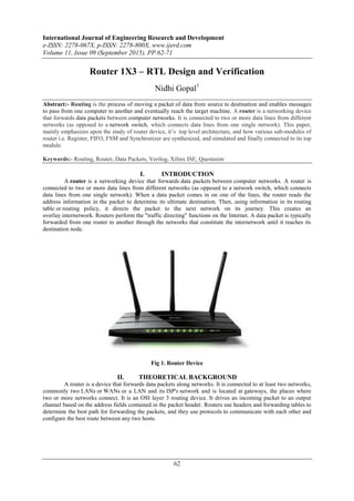
  • 1. International Journal of Engineering Research and Development e-ISSN: 2278-067X, p-ISSN: 2278-800X, www.ijerd.com Volume 11, Issue 09 (September 2015), PP.62-71 62 Router 1X3 – RTL Design and Verification Nidhi Gopal1 Abstract:- Routing is the process of moving a packet of data from source to destination and enables messages to pass from one computer to another and eventually reach the target machine. A router is a networking device that forwards data packets between computer networks. It is connected to two or more data lines from different networks (as opposed to a network switch, which connects data lines from one single network). This paper, mainly emphasizes upon the study of router device, it‟s top level architecture, and how various sub-modules of router i.e. Register, FIFO, FSM and Synchronizer are synthesized, and simulated and finally connected to its top module. Keywords:- Routing, Router, Data Packets, Verilog, Xilinx ISE, Questasim I. INTRODUCTION A router is a networking device that forwards data packets between computer networks. A router is connected to two or more data lines from different networks (as opposed to a network switch, which connects data lines from one single network). When a data packet comes in on one of the lines, the router reads the address information in the packet to determine its ultimate destination. Then, using information in its routing table or routing policy, it directs the packet to the next network on its journey. This creates an overlay internetwork. Routers perform the "traffic directing" functions on the Internet. A data packet is typically forwarded from one router to another through the networks that constitute the internetwork until it reaches its destination node. Fig 1. Router Device II. THEORETICAL BACKGROUND A router is a device that forwards data packets along networks. It is connected to at least two networks, commonly two LANs or WANs or a LAN and its ISP's network and is located at gateways, the places where two or more networks connect. It is an OSI layer 3 routing device. It drives an incoming packet to an output channel based on the address fields contained in the packet header. Routers use headers and forwarding tables to determine the best path for forwarding the packets, and they use protocols to communicate with each other and configure the best route between any two hosts.
  • 2. Router 1X3 – RTL Design and Verification 63 Figure below, shows top level architecture of router, which include components like FIFO, Register, synchronizer, FSM and input and output signals between them. Diagrammatic Comparison between OSI Reference Model and TCP/IP Reference Model 1. Router packet: Packet format: the packet consists of 3 parts: Header, payload and parity each of 8 bit width and the length of the payload can be extended between 3 between 1 byte to 63 byte.
  • 3. Router 1X3 – RTL Design and Verification 64  Header: Packet header contain two fields DA and length.  DA: destination address of the packet is of 2 bits. The router drives the packet to the respective ports based on this destination address of the packets. Each output port has 2-bit unique port address. If the destination address of the packet matches the port address, then router drives the packet to the output port. The address „3‟ is invalid.  Length: length of the data is of 6-bits. It specifies the number of the number of the data bytes. A packet can have a minimum data size of 1 byte and a maximum size of 63 bytes. If length =1, it means data length is 1 byte If length =2, it means data length is 2 bytes If length =63, it means data length is 63 bytes  Payload: payload is the data information. Data should be in terms of the bytes.  Parity: This field contains the security check of the packet. It is calculated as bitwise parity over the header and payload bytes of the packet as mentioned below. 2. Router Input Protocol: The characteristics of the DUT input protocols are as follows:  Testbench Notes: All input signals are active high except low reset and are synchronized to the falling edge of the clock. This is because the DUT router is sensitive to the rising edge of the clock. Therefore, in the testbench, driving input signals on the falling edge ensures setup and hold time. But in the system Verilog/UVM based testbench, clocking block can be used to drive the signals on the positive edge of the clock itself and thus avoids metastability.  The packet_valid signal is asserted on the same clock edge when the header byte driven onto the input data bus.  Since the header byte contains the address, this the router to which output channel the packet should be routed to (data_out_0, data_out_1, data_out_2).  Each subsequent byte of payload after header byte should be driven on the input data bus for every new falling edge of the clock.
  • 4. Router 1X3 – RTL Design and Verification 65  After the last payload byte has been driven, on the next falling edge of the clock, the packet_valid signal must be de-asserted, and the packet parity should be driven. This signals packet completion.  The testbench shouldn`t drive any byte when busy signal is detected instead it should hold the last driven values.  The `busy` signal when asserted drops any incoming byte of the data.  The “err” signal is asserted when a packet parity mismatch is detected. 3. Router Output Protocol The characteristics of the output protocol are as follows:  Test bench Note: All output signals are active high and are synchronized to the rising edge of the clock.  Each output port data_out_X (data_out_0, data_out_1, data_out_2) is internally buffered by a FIFO of size 16X9.  The router asserts the vld_out_X (vld_out_0, vld_out_!, vld_out_2) signal when valid data appears on the vld_out_X(data_out_0,data_out_1,data_out_2) output bus. This is a signal to the receiver‟s client which indicates the data is available on a particular output data bus.  The packet receiver will then wait until it has enough space to hold the bytes of the packet and then respond with the assertion of the read_enb_X(read_enb_0.read_enb_1,read_enb_2) signal.  The read_enb_X(read_enb_0,read_enb_`1 or read_enb_2) input signal can be asserted on the falling clock edge in which data are read from the data_out_X(data_out_0,data_out_1,data_out_2)bus.  The read_enb_X(read_enb_0,read_out_1 or read_out_2) must be asserted within 30 clock cycles of the vld_out_X(vld_out_0,vld_out_1,vld_out_2) being asserted else time-out occurs, which resets the FIFO.  The data_out_X (data_out_0,data_out_1 or data_out_2) bus will be tri-stated(high Z) during a scenario when a packet‟s header byte is lost due to time-out condition . 4. Router- Top Level block The top level architecture of router is shown in the figure. The router module consists of FSM, REGISTER, SYNCHRONIZER, FIFO_0, FIFO_1, FIFO_2. During the course of the designing and implementing the whole module, we design each sub-module one by one individually using RTL coding in Verilog and then from the top we will instantiate all sub-module using structural style of modeling and using some constructs of advance Verilog also. 5. Router : FIFO Functionality There are 3 FIFOs used in the router design. Each FIFO is of 9 bits wide and 16 bit bytes depth. The FIFO works on the system clock and is reset with a synchronizer active low reset.The FIFO is also internally reset by an internal reset signal soft_reset. Soft_reset is an active high signal which is generated by the SYNCHRONIZER block during time out state of the ROUTER. If resetn is low then full=0, empty=1 and data_out=0.
  • 5. Router 1X3 – RTL Design and Verification 66 The FIFO m/m size is 16X9. The extra bit in the data width is appended in order to detect the header byte. Lfd_state detects the header byte of a packet. The 9th bit is 1 for header byte and 0 for the remaining bytes. Write Operation:  Signal data_in is sampled at the rising edge of the edge of the clock when write_enb is high.  Write operation only takes place when FIFO is not full in order to avoid over_run condition. Read operation:  The data is read from data_out at rising edge of the clock, when read_enb is high.  Read operation only takes place when the FIFO is not empty in order to avoid under run condition.  During the read operation when a header byte is read, an internal counter is loaded with the payload length of the packet plus „1‟ (parity byte) and starts decrementing every clock till it reached 0. The counter holds 0 till it is reloaded back with a new packet payload length.  During the time out condition, full=0, empty=1.  data out is driven to HIGH impedance state under 2 scenarios:  When the fifo m/m is read completely (header+payload+parity).  Under the time out condition of the Router.  Full- FIFO status which indicates that all the locations inside FIFO have been written.  Empty- FIFO status which indicates that all the locations of the FIFO have been read and made empty.  Read and write operation can be done simultaneously. 6. ROUTER : SYNCHRONIZER Functionality: This module provides synchronization between router FSM and router FIFO modules. It provides faithful communication between the single input port and three output ports.  detect_add and data_in signals are used to select a FIFO till a packet routing is over for the selected FIFO.  Signal fifo_full signal is asserted based on full_status of fifo_0 or FIFO_1 or FIFO_2.  If data_in =2‟b00 then fifo_full=full_0  If data_in=2‟b01 then fifo_full=full_1  If data_in=2‟b10 then fifo_full=full_2 else fifo_full=0  The signal vld_out_x signal is generated based on empty status of the FIFO as shown below :  vld_out_0=~empty_0  vld_out_1=~empty_1  vld_out_2=~empty_2  The write_enb_reg signal is used to generate write_enb signal for the write operation of the selected FIFO.  There are 3 internal reset signals (soft_reset_0, soft_reset_1, soft_reset_2) for each of the FIFO respectively. The respective internal reset signals goes high if read_enb_X (read_enb_0,read_out_1,read_out_2) is not asserted within 30 clock cycles of the vld_out_X(vld_out_0,vld_out_1 or vld_out_2) being asserted respectively.
  • 6. Router 1X3 – RTL Design and Verification 67 7. ROUTER: FSM STATE-DECODE_ADDRESS  This is the initial reset state.  Signal detect_add is asserted in this state which is used to detect an incoming packet. It is also used to latch the first byte as a header byte. STATE-LOAD_FIRST_DATA  Signal lfd_state is asserted in this state which is used to load the first data byte to the FIFO.  Signal busy is also asserted in this state so that header byte that is already latched doesn‟t update to a new value for the current packet.  This state is changed to LAOD_DATA state unconditionally in the next clock cycle. STATE-LOAD_DATA  In this state the signal ld_state is asserted which is used to load the payload data to the FIFO.  Signal busy is de asserted in this state, so that ROUTER can receive the new data from input source every clock cycle,  Signal write_enb_reg is asserted in this state in order to write the Packet information (Header+Payload+Parity) to the selected FIFO.  This state transits to LAOD_PARITY state when pkt_valid goes low and to FIFO_FULL_STATE when FIFO is full. STATE-LOAD_PARITY  In this state the last byte is latched which is the parity byte.  It goes unconditionally to the state CHECK_PARITY_ERROR.  Signal busy is asserted so that ROUTER doesn‟t accepts any new data.  write_enb_reg is made high for latching the parity byte to FIFO. STATE-FIFO_FULL_STATE  Busy signal is made high and write_enb_reg signal is made low.  Signal full_state is asserted which detects the FIFO full state. STATE-LOAD_AFTER_FULL  In this state laf_state signal is asserted which is used to latch the data after FIFO_FULL_STATE.  Signal busy & write_enb_reg is asserted.  It checks for parity_done signal and if it is high, shows that LOAD_PARITY state has been detected and it goes to the state DECODE_ADDRESS.  If low_packet_valid is high it goes to LOAD_PARITY state otherwise it goes back to the LOAD_DATA state. STATE-WAIT_TILL_EMPTY  Busy signal is made high and write_enb_reg signal is made low. STATE-CHECK_PARITY_ERROR  In this state rst_int_reg signal is generated, which is used to reset low_packet_valid signal.  This state changes to DECODE_ADDRESS when FIFO is not full and to FIFO_FULL_STATE when FIFO is full.  Busy is asserted in this state.
  • 7. Router 1X3 – RTL Design and Verification 68 8. ROUTER: Register Functionality: This module implements 4 internal registers in order to hold a header byte, FIFO full state byte, internal parity and packet parity byte. All the registers in this module are latched on the rising edge of the clock.  If resetn is low then the signals (dout,err,parity_done and low_pkt_valid) are low.  The signal parity_done is high under the following conditions:  When signal ld_state is high and signals (fifo_full and pkt_valid) are low.  When signals laf_state and low_pkt_valid both are high and the previous value of parity_done is low.  rst_int_reg signal is used to reset low_pkt_valid signal.  detect_add signal is used to reset parity_done signal.  Signal low_pkt_valid is high when ld_state is high and pkt_valid is low. Low_packet_valid shows that pkt_valid for current state has been deasserted.  First data byte i.e., header is latched inside an internal register when detect_add and pkt_valid signals are high. This data is latched to the output dout when lfd_state goes high.  Then signal data_in i.e. Payload is latched to dout if ld_state signal is high and fifo_full is low.  Signal data_in is latched to an internal register when ld_state and fifo_full are high. This data is latched to output dout when laf_state goes high.  Full_state is used to calculate internal parity.  Another internal register is used to store internal parity for parity matching. Internal parity is calculated using the bit-wise xor operation between header byte, payload byte and previous parity values as shown below: parity_reg=parity_reg_previous^header_byte ---- t1 clock cycle parity_reg=parity_reg_previous^header_byte ---- t1 clock cycle parity_reg=parity_reg_previous^header_byte ---- t1 clock cycle parity_reg=parity_reg_previous^header_byte ---- t1 clock cycle Last payload byte  The err is calculated only after packet parity is loaded and goes high if the packet parity doesn‟t match with the internal parity. III. SIMULATION RESULTS Following components of router were synthesized and simulated, using Xilinx ISE software. And Simulation results were observed. Following are the results obtained:
  • 8. Router 1X3 – RTL Design and Verification 69 Figure: Fifo output Figure: Fsm output
  • 9. Router 1X3 – RTL Design and Verification 70 Figure: Synchronizer output Figure: Top output IV. CONCLUSION The Router1X3 is designed and verified successfully. Many coding bugs are debugged during the verification. Scenarios like packets with payload length  8 byte  14 byte  16 byte  17 byte  FIFO full state(observing busy signal)  good packet  packet which is never read
  • 10. Router 1X3 – RTL Design and Verification 71  Simultaneous read write operation  Bad packet/corrupt packet were driven from the testbench to determine the robustness of the design. And it was working seamlessly as shown by the coverage report produced by Questasim with 100% FSM state coverage, 81.81% FSM transition coverage, 96.42% toggle coverage, 92.40% statement coverage. Figure: Coverage Summary: By structure, by type Figure: Coverage report by instance Figure: Coverage Report ACKNOWLEDGEMENT The author would like to thank Mrs. Susmita Nayak, and Mr. Putta Satish for their proper guidance, continuous support and engagement in this research. REFERENCES [1]. Verilog HDL:- Samir Palnitkar [2]. System Verilog:- Chris Spear [3]. The ASIC Website: www.asicworld.com [4]. www.google.com/fifo-theory-verilog [5]. www.wikipedia.com