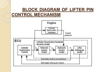
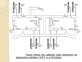
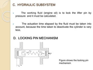
This document discusses cylinder deactivation systems, which deactivate cylinders to improve fuel efficiency when full engine power isn't needed. It introduces the topic and explains that cylinder deactivation was developed to reduce fuel consumption in cities where less power is required. It then describes three main methods: lifter pin control mechanism, variable profile camshaft, and active valve train technology. For lifter pin control mechanism, it provides details on how solenoid valves and locking pins deactivate cylinders to decouple the camshaft. Cylinder deactivation systems can increase fuel efficiency and decrease emissions, but also result in increased vehicle weight and manufacturing costs.
The heart of an automobile is its engine, and the heart requires a constant and ingenuous supply of blood, fuel in this case. There had been carburetors faithfully doing this holy work, but technology never seizes to move up. Therefore, the latest offering is the fuel injector for petrol engin es. Though it all started with a simple objective of supplying a controlled amount of fuel at proper intervals of time, it’s, as of now, not as simple as that. With emission norms getting stricter and changing trends in engine technology – high-speed engines, Variable displacement engines, Hybrid engines, etc – it became more and more of a necessity than a luxury to improve the fuel supply system.
Today’s fuel injection unit not only improves engine performance, but also helps in giving a cleaner exhaust that too with a increased fuel economy. The objectives can be attained using a microprocessor that directs the injector using a number of various input parameters. These parameters include manifold temperatures, throttle position, ignition timing, engine speed, load, and a lot more of other factors. The various strategically placed sensors measures these physical quantities and convey the same to the processor in electronic signals. The paper deals with the brief functionality and basic concept of operation of a modern fuel injector used in petrol engines.
Transmission is a part of the car which connects the engine to the wheels. When car speeds up, the engine can not speed up in the same proportion, so there are gears involved which match the engine speed to the wheel speed so that we can drive faster or slower than the engine speed.
Electronic fuel injection vs carburettorsSalman Ahmed
These slides give you an idea of the different types of fuel injection systems that have been used throughout time.
A comparison between carburettors and EFI has been also looked on.
Electronic Power Steering (EPS) by Gaurav RaikarGauravRaikar3
This presentations describes electronic power steering types.
1.Hydraulic power steering system(HPS)
2.Electro-hydraulic power steering system(EHPS)
3.Electronic power system(EPS)
CVT transmission can change seamlessly through an infinite number of effective gear ratios between maximum and minimum values giving jerk free driving experience.
In this presentation we mainly discuss about Variable-diameter pulley (VDP) and how basically it functions.
it is a ppt on koenigsegg camless valves which are new inventions in ic engine here its principle and working have been explaned.and also working of conventional engine habe been explained.
With the development of technologies such as VVT (Variable Valve Timing) and VVL (Variable Valve lift) controlled by ECU resulted in the development of modern ivtec, multiair and other advance engines which not only improved performance but also were energy efficient with less NOx emissions.
An introduction to the concept of Cam-Less engines which replaces the conventional Cam and follower assembly with Electro -Mechanical or Electro-Hydraulic actuators controlled by PDM and ECU for better control and improving efficiency of an I.C.Engine.A theoretically simple but practically complex kit of technology which although beneficiary has its limitations and comes with a huge development and production cost.For better insight search for the same on Youtube.
https://youtu.be/XrYt1JHNmh4
An interesting take on this.
An i-VTEC is new technology introduce by the honda in the field of automobile. This technology is most famous and installed in all cars of the honda. In this presentation on i-VTEC you will find all about it like its working principle, its performance, its advantages and disadvantages and further development in this technology. A complete illustration about this technolgy is given in this presentation.
Cosmetic shop management system project report.pdfKamal Acharya
Buying new cosmetic products is difficult. It can even be scary for those who have sensitive skin and are prone to skin trouble. The information needed to alleviate this problem is on the back of each product, but it's thought to interpret those ingredient lists unless you have a background in chemistry.
Instead of buying and hoping for the best, we can use data science to help us predict which products may be good fits for us. It includes various function programs to do the above mentioned tasks.
Data file handling has been effectively used in the program.
The automated cosmetic shop management system should deal with the automation of general workflow and administration process of the shop. The main processes of the system focus on customer's request where the system is able to search the most appropriate products and deliver it to the customers. It should help the employees to quickly identify the list of cosmetic product that have reached the minimum quantity and also keep a track of expired date for each cosmetic product. It should help the employees to find the rack number in which the product is placed.It is also Faster and more efficient way.
CFD Simulation of By-pass Flow in a HRSG module by R&R Consult.pptxR&R Consult
CFD analysis is incredibly effective at solving mysteries and improving the performance of complex systems!
Here's a great example: At a large natural gas-fired power plant, where they use waste heat to generate steam and energy, they were puzzled that their boiler wasn't producing as much steam as expected.
R&R and Tetra Engineering Group Inc. were asked to solve the issue with reduced steam production.
An inspection had shown that a significant amount of hot flue gas was bypassing the boiler tubes, where the heat was supposed to be transferred.
R&R Consult conducted a CFD analysis, which revealed that 6.3% of the flue gas was bypassing the boiler tubes without transferring heat. The analysis also showed that the flue gas was instead being directed along the sides of the boiler and between the modules that were supposed to capture the heat. This was the cause of the reduced performance.
Based on our results, Tetra Engineering installed covering plates to reduce the bypass flow. This improved the boiler's performance and increased electricity production.
It is always satisfying when we can help solve complex challenges like this. Do your systems also need a check-up or optimization? Give us a call!
Work done in cooperation with James Malloy and David Moelling from Tetra Engineering.
More examples of our work https://www.r-r-consult.dk/en/cases-en/
Sachpazis:Terzaghi Bearing Capacity Estimation in simple terms with Calculati...Dr.Costas Sachpazis
Terzaghi's soil bearing capacity theory, developed by Karl Terzaghi, is a fundamental principle in geotechnical engineering used to determine the bearing capacity of shallow foundations. This theory provides a method to calculate the ultimate bearing capacity of soil, which is the maximum load per unit area that the soil can support without undergoing shear failure. The Calculation HTML Code included.
Hybrid optimization of pumped hydro system and solar- Engr. Abdul-Azeez.pdffxintegritypublishin
Advancements in technology unveil a myriad of electrical and electronic breakthroughs geared towards efficiently harnessing limited resources to meet human energy demands. The optimization of hybrid solar PV panels and pumped hydro energy supply systems plays a pivotal role in utilizing natural resources effectively. This initiative not only benefits humanity but also fosters environmental sustainability. The study investigated the design optimization of these hybrid systems, focusing on understanding solar radiation patterns, identifying geographical influences on solar radiation, formulating a mathematical model for system optimization, and determining the optimal configuration of PV panels and pumped hydro storage. Through a comparative analysis approach and eight weeks of data collection, the study addressed key research questions related to solar radiation patterns and optimal system design. The findings highlighted regions with heightened solar radiation levels, showcasing substantial potential for power generation and emphasizing the system's efficiency. Optimizing system design significantly boosted power generation, promoted renewable energy utilization, and enhanced energy storage capacity. The study underscored the benefits of optimizing hybrid solar PV panels and pumped hydro energy supply systems for sustainable energy usage. Optimizing the design of solar PV panels and pumped hydro energy supply systems as examined across diverse climatic conditions in a developing country, not only enhances power generation but also improves the integration of renewable energy sources and boosts energy storage capacities, particularly beneficial for less economically prosperous regions. Additionally, the study provides valuable insights for advancing energy research in economically viable areas. Recommendations included conducting site-specific assessments, utilizing advanced modeling tools, implementing regular maintenance protocols, and enhancing communication among system components.
Event Management System Vb Net Project Report.pdfKamal Acharya
In present era, the scopes of information technology growing with a very fast .We do not see any are untouched from this industry. The scope of information technology has become wider includes: Business and industry. Household Business, Communication, Education, Entertainment, Science, Medicine, Engineering, Distance Learning, Weather Forecasting. Carrier Searching and so on.
My project named “Event Management System” is software that store and maintained all events coordinated in college. It also helpful to print related reports. My project will help to record the events coordinated by faculties with their Name, Event subject, date & details in an efficient & effective ways.
In my system we have to make a system by which a user can record all events coordinated by a particular faculty. In our proposed system some more featured are added which differs it from the existing system such as security.
Welcome to WIPAC Monthly the magazine brought to you by the LinkedIn Group Water Industry Process Automation & Control.
In this month's edition, along with this month's industry news to celebrate the 13 years since the group was created we have articles including
A case study of the used of Advanced Process Control at the Wastewater Treatment works at Lleida in Spain
A look back on an article on smart wastewater networks in order to see how the industry has measured up in the interim around the adoption of Digital Transformation in the Water Industry.
Water scarcity is the lack of fresh water resources to meet the standard water demand. There are two type of water scarcity. One is physical. The other is economic water scarcity.
2. INTRODUCTION
This topic focuses about the reduction of fuel
consumption of an internal combustion engine.
The power required is very less inside the city than the
peak power generated by the car.
This mechanism is introduced in 1981 by General
Motors .
It keeps on developing by adding new technologies by
car manufacturing companies.
3. MECHANISM
This is the method of deactivating engine
cylinders according to requirement of power to
achieve better fuel efficiency and also emission
control.
It works because only a small fraction of an
engine’s peak horsepower is needed to maintain
cruising speed.
Each cylinder is disabled only at the intake and
exhaust stroke. It takes 40 to 50 milliseconds.
Each cylinder is disabled by interrupting the
operation of intake and exhausts valves with spark
and fuel delivery.
4. METHODS FOR CYLINDER
DEACTIVATION SYSTEM
Lifter Pin Control Mechanism
Variable Profile Cam Shaft
Active Valve Train Technology.
5. I. LIFTER PIN CONTROL
MECHANISM
This mechanism consists of four subsystem:
Electronic Control Module
Solenoid Valves
Hydraulic Subsystem
Lifter locking pin mechanism
PRINCIPLE OF OPERATION
When the solenoid valve is energized, the oil
becomes pressurized in the control port, the pressure force acts
on the pins and makes it lock.
It decouples the camshaft from the valves(i.e. inlet
and outlet manifold). So the cylinder is deactivated.
7. A. ELECTRONIC CONTROL MODULE
It measures the performance of engine at
all events to enable full time control.
It also calculates the total actuation
time elapsed by all the systems.
B. SOLENOID VALVE OPERATION
A 3-way normally closed direct current
ONOFF solenoid valve. The common port of the
valve is connected to an oil gallery.
The common port is switched to engine oil
pressure for deactivation of cylinder(valve energized)
.
9. Figure shows the solenoid valve placement for
deactivation cylinders 1,4,6,7 in a V8 engine.
10. C. HYDRAULIC SUBSYSTEM
The working fluid (engine oil) is to lock the lifter pin by
pressure and it must be calculated.
The actuation time elapsed by the fluid must be taken into
account, because the time taken to deactivate the cylinder is very
less.
D. LOCKING PIN MECHANISM
Figure shows the locking pin
mechanism
11. The common port of the control valve is
connected via an oil gallery to a pair of spring based
locking pins inside the valve lifter.
When the pins are locked the camshaft is
decoupled from the engine valve. So that we
deactivate the cylinder.
It is desirable to change the switching sequence
of cylinder-by-cylinder and to complete transition from
V8 to V4.
12. METHODS USED IN LIFTER PIN CONTROL
MECHANISM
1. Cylinder Bank Control.
In this method the 2 cylinders from each bank is
selected for deactivation.
This control method is mainly used in inline
cylinder engines
2. Individual Cylinder Control.
In this method each cylinder is deactivated
independently and its selection depends on firing order.
This control method is mainly used in Boxer
engines and V engines.
13. II. VARIABLE PROFILE CAMSHAFT MECHANISM
This system allows the engine to have multiple cam
shafts.
As the engine moves into different r.p.m computer can
activate alternate lobes on the camshaft and change the
cam timings.
This system uses a Cam Profile Switching tappet, to
switch between two different cam profiles. In this way the
engine gets best features of low speed as well as high
speed camshaft of same engine.
This is similar to the patented V-Tech technology used in
Honda.
14. III. ACTIVE VALVE TRAIN TECHNOLOGY
This system uses electrohydraulic operation, movement
of engine poppet valves initiated by oil flow into and out of
the hydraulic chamber.
It is controlled by fast acting electrohydraulic servo
valves, this inturn allows variable timing, duration and lift
Increased combustion control due to variable lift and it
offers fuel consumption benefits over conventional
camshaft driven valve actuation mechanisms.
But this method is still in experimental stage to rectify
the disadvantages.
15. Figure show the CAD Model of inlet and exhaust valve of a single
cylinder
16. ADVANTAGES OF CYLINDER DEACTIVATED
ENGINES
1. Increased fuel efficiency (10-25%).
2. Decreased emissions from deactivated cylinders.
3. Better breathing capability of the engine, thereby
reducing the power consumed in suction stroke.
17. DISADVANTAGES
1. Engine balancing – Deactivating cylinders can cause
change in engine balancing which leads to violent
vibration and noises. The way of attaching counter
masses to the moving parts like crankshaft is very
difficult to calculate and attach the counter masses.
2. Increased cost of manufactuing – Though the
deactivation process reduces operation costs, the
additional parts like ECM and others will increase the
cost of manufacturing.
3. Overall increase in weight
4. Complexity of system makes maintenance difficult.
5. Since these methods are still under experimental stage,
the reliability of the engine is not predicted yet.
18. CONCLUSION
To reduce the pollution from the internal
combustion engines and the demand of
automobile which burns less fuel.
With the increase of price of petroleum
products the fuel is burnt according to the
power requirement.
So, Cylinder deactivation solve these
problems to a great extend without
compromising engine performance thus
satisfies both manufacturer and consumer.
19. REFERENCES
Research paper published by Quant Zheng, Delphi
Motors.
Internet.
Research paper published by Lotus and Eaton
Automotive Systems.