Download to read offline

![Classification of IC engines
Two main classifications:
Based on combustion
Spark Ignition [SI engines] (Eg: Petrol Engine)
Compression Ignition [CI engines] (Eg: Diesel
Engine)
Based on Number of strokes
Two stroke
Four Stroke
Six Stroke](https://image.slidesharecdn.com/advancementoficengine-200717170019/85/Advancement-of-IC-engine-4-320.jpg)
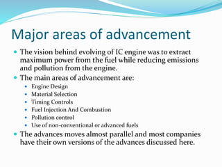
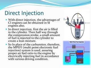
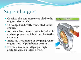
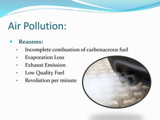
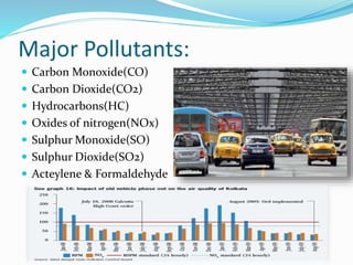
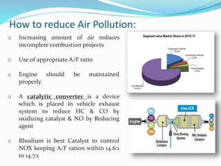


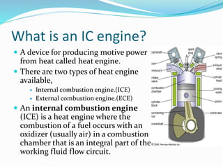
The document discusses the advancement of internal combustion engines. It covers topics like the classification of IC engines based on combustion and strokes. Major areas of advancement discussed include engine design, material selection, timing controls, fuels and fuel injection systems, and pollution control. Some specific technologies covered are variable valve timing, direct injection, superchargers, turbochargers, six-stroke engines, and methods to reduce air pollution from engines like catalytic converters. The goals of engine advancement are listed as higher power, better fuel efficiency, lower emissions and weight.