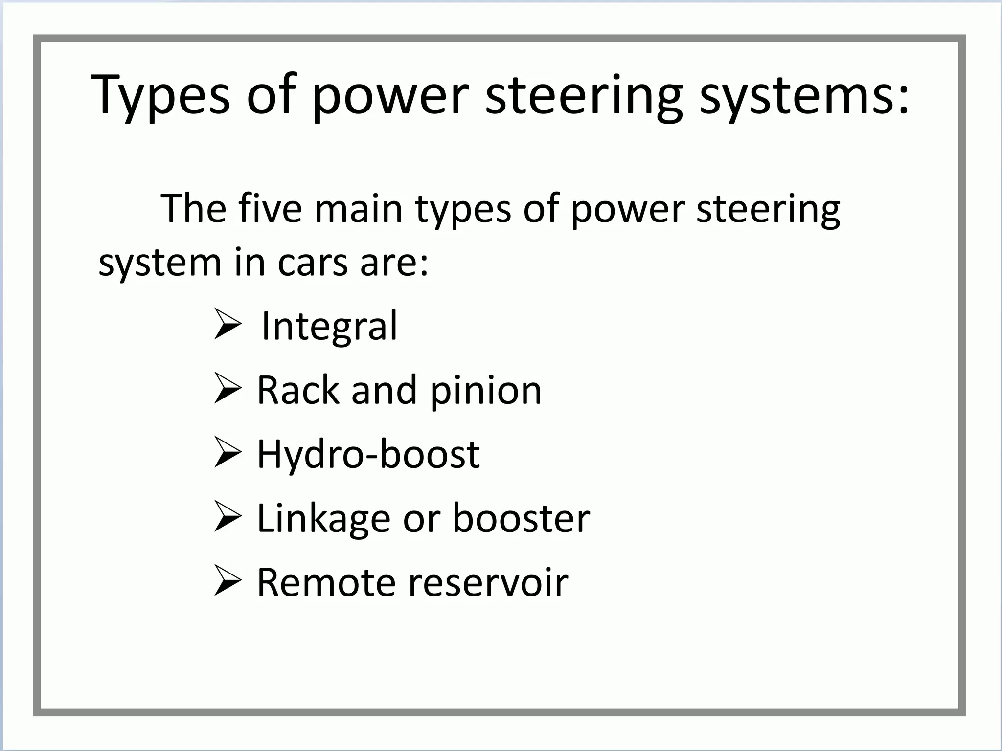
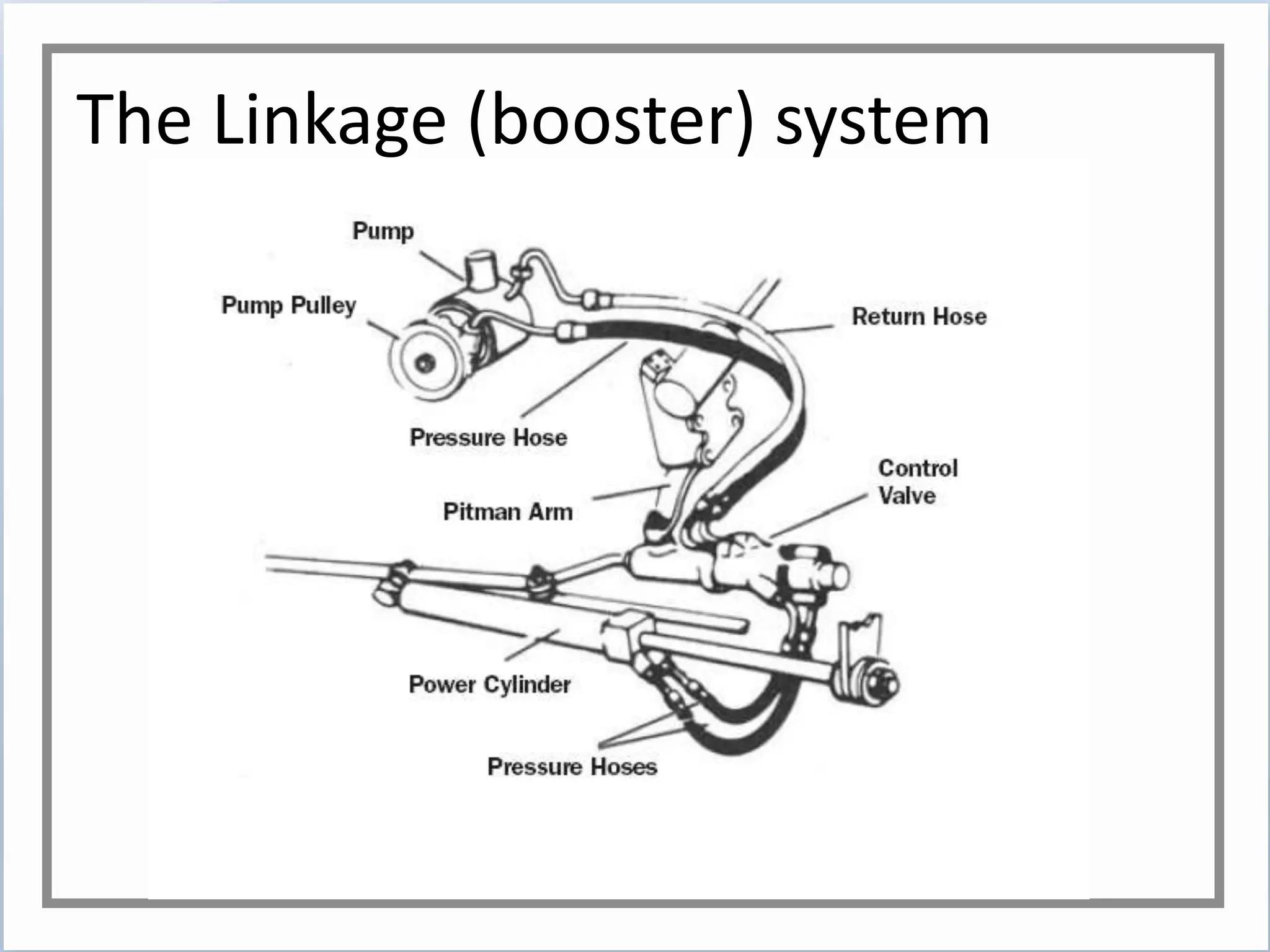
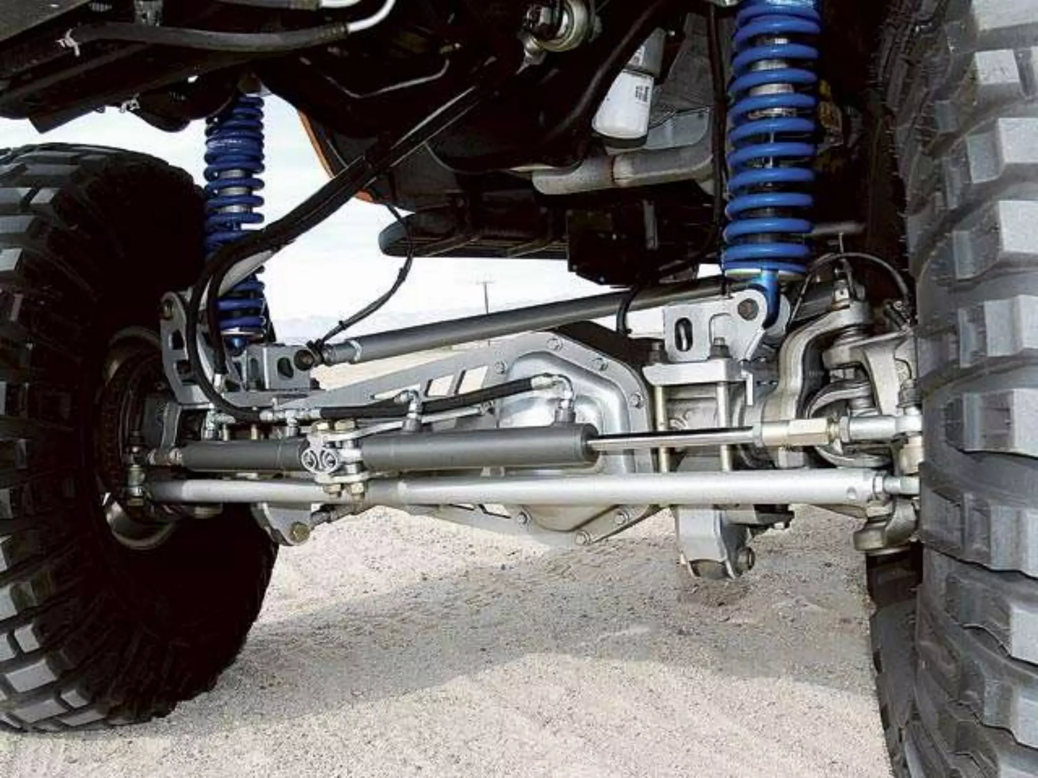
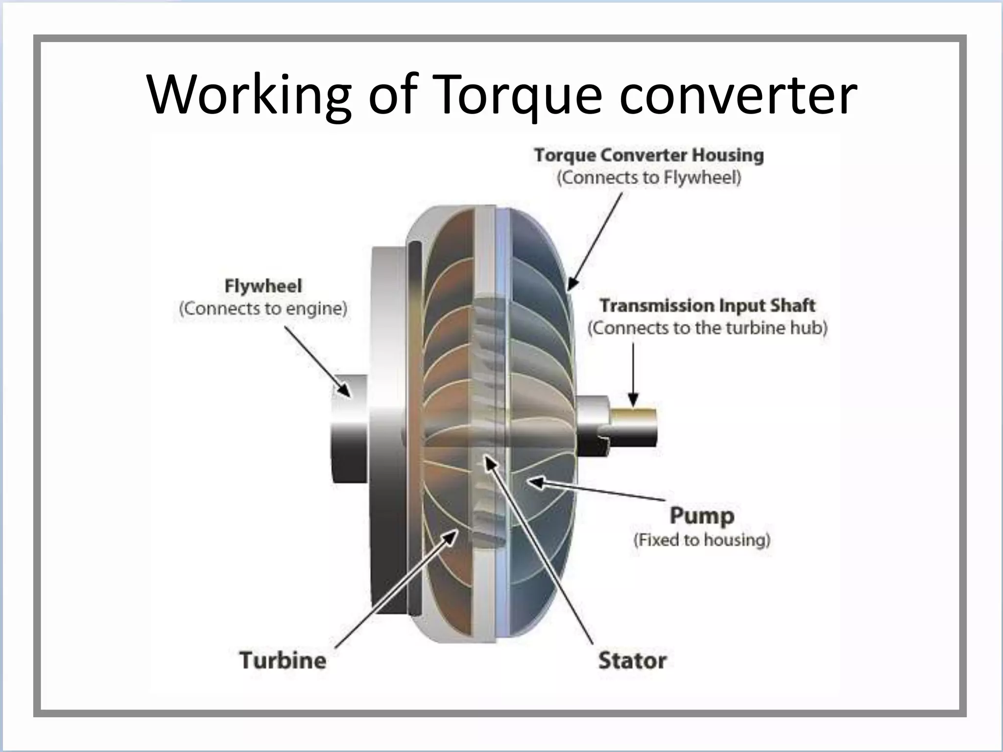
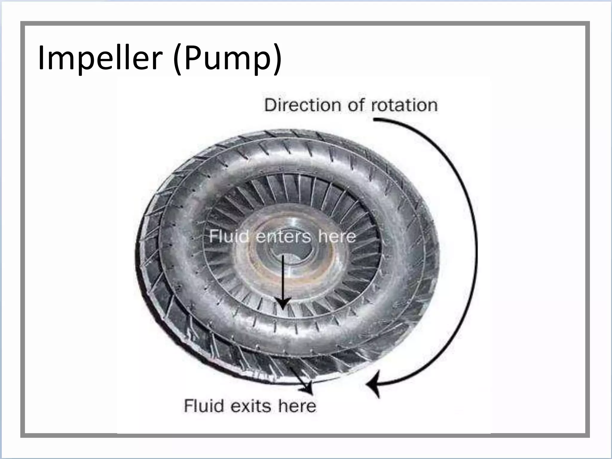
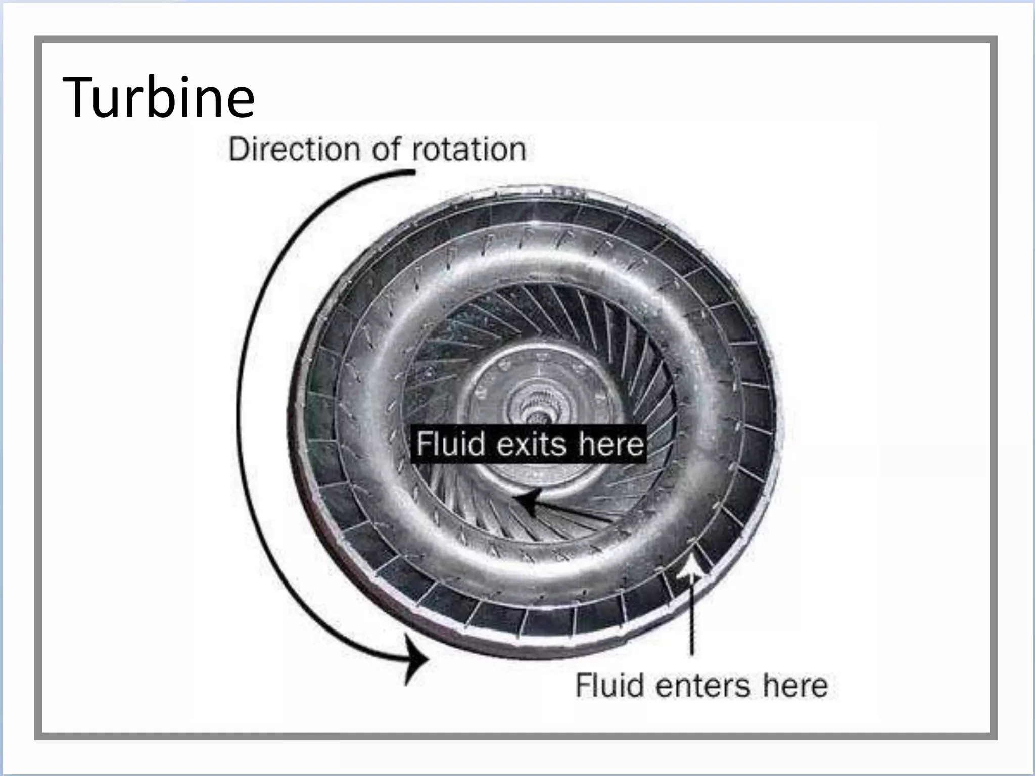
HYDRAULICS IN AUTOMOTIVES
BY
ARAHVINTH O L K
HYDRAULIC POWER
STEERING
What is power steering?
It is a hydraulic system which assists the driver in
reducing the steering effort on vehicles.
It utilizes hydraulic pressure in turning the front
wheels of the automobile(car).
The system usually consists of a hydraulic pump and
fluid reservoir, a power-actuating mechanism such as a
power cylinder, a control valve arrangement, and a series
of flexible hydraulic hoses and couplings to route the
hydraulic fluid under pressure.
Types of power steering systems:
The five main types of power steering
system in cars are:
 Integral
 Rack and pinion
 Hydro-boost
 Linkage or booster
 Remote reservoir
Integral system
In integral system, the power cylinder and the control valve
functions are combined into one unit located in the steering
gearbox at the steering column’s end.
Here, a pressure flow director valve senses steering wheel
movement and directs the fluid pressure to either side of a rack
piston, which is directly geared to the pitman arm shaft.
As the rack piston travels up or down under fluid pressure,
the pitman shaft rotates, applying the needed boost to turn the
wheels.
The spent fluid is then re-circulated back to the pump
reservoir.
The pressure line must withstand pressures ranging from
800 to 1300 psi. The return line normally kept less than 50 psi.
Integral system
Rack and pinion system
In rack and pinion type, the gear on the steering column’s
end is similar to the pinion gear in the differential: cut on an
angle, and meshed with a steel bar (the rack) toothed on one
side.
The rack is mounted parallel to the front axle and as the
steering wheel turns, it operates directly on the tie rods without
the use of a pitman arm, idler or intermediate (or relay) rod.
Adding a power assist to this type of steering is quite
simple. The power piston is actually part of the rack, and the
rack housing acts as the cylinder.
The control valve is located in the pinion housing.
Rotation of the steering shaft and pinion turns the valve to
direct hydraulic pressure to either end of the rack piston.
Rack and pinion system
The Linkage (booster) system
In the linkage system, the pump supplies hydraulic pressure
to a control valve assembly attached to the pitman arm and
intermediate rod. This control valve senses, by mechanical
means, the steering wheel movement in either direction.
The valve then directs the proper amount of hydraulic
pressure to the power cylinder attached to the car’s frame on
one end and to the intermediate rod on the other.
As fluid pressure is applied to either end of the power
cylinder, it pushes or pulls the intermediate rod to affect the
steering boost.
The fluid is then re-directed back to the pump reservoir via
the return hose line.
The pressure and cylinder lines must withstand pressure
ranging from 800 to 1,100 psi. The return line normally carries
up to 40 psi.
The Linkage (booster) system
AUTOMATIC TRANSMISSION-
TORQUE CONVERTERS
Torque Converter
The torque converter in an automatic transmission serves
the same purpose as the clutch in a manual transmission.
A torque converter is a fluid coupling that is used to transfer
rotating power from a prime mover, such as an IC engine or
electric motor, to a rotating driven load.
As a more advanced form of fluid coupling, however, a
torque converter is able to multiply torque when there is a
substantial difference between input and output rotational
speed, thus providing the equivalent of a reduction gear.
Parts of a torque converter:
There are four components inside the very
strong housing of the torque converter:
 Pump (Impeller)
Turbine
Stator
Transmission fluid
TORQUE CONVERTER
Working of Torque converter
Impeller (Pump)
The housing of the torque converter is bolted to the
flywheel of the engine, so it turns at whatever speed the engine
is running at.
The fins that make up the pump of the torque converter are
attached to the housing, so they also turn at the same speed as
the engine.
The pump inside a torque converter is a type of centrifugal
pump. As it spins, fluid is flung to the outside, much as the spin
cycle of a washing machine flings water and clothes to the
outside of the wash tub.
As fluid is flung to the outside, a vacuum is created that
draws more fluid in at the center.
Impeller (Pump)
Turbine
The fluid then enters the blades of the turbine, which is
connected to the transmission. The turbine causes the
transmission to spin, which basically moves your car. The blades
of the turbine are curved. This means that the fluid, which
enters the turbine from the outside, has to change direction
before it exits the center of the turbine. It is this directional
change that causes the turbine to spin. So as the turbine causes
the fluid to change direction, the fluid causes the turbine to spin.
The fluid exits the turbine at the center, moving in a
different direction than when it entered. It is seen that the fluid
exits the turbine moving opposite the direction that the pump
(and engine) are turning. If the fluid were allowed to hit the
pump, it would slow the engine down, wasting power. This is
why a torque converter has a stator.
Turbine
Stator
The stator resides in the very center of the torque
converter. Its job is to redirect the fluid returning from the
turbine before it hits the pump again. This dramatically increases
the efficiency of the torque converter.
The stator has a very aggressive blade design that almost
completely reverses the direction of the fluid. A one-way clutch
(inside the stator) connects the stator to a fixed shaft in the
transmission (the direction that the clutch allows the stator to
spin).
Because of this arrangement, the stator cannot spin with
the fluid -- it can spin only in the opposite direction, forcing the
fluid to change direction as it hits the stator blades.
Stator
Advantages:
Noise insulation
Good fuel consumption
Less wear on the transmission
Better starting dynamics and more
driving pleasure when engine power
remains the same.
Hydropneumatic suspension
• Introduced by Citroën in 1954
• Commonly used by Mercedes-
Benz,RR,Peugeot.
• Purpose
To provide soft,comfortable yet well
controlled ride quality
Setup
• N2 filled chambers called ‘spheres’
• One sphere per wheel with one main
accumulator
• Hollow metal ball with desmopan rubber
membrane
• Nitrogen pressure-75 bar
Layout
Working
Pump powered by engine fills and pressurizes
the accumulator-150 to 180 bars
Powers the front brakes first
Next the bottom of the spheres are filled with oil
Suspension works by means of compacting the
nitrogen in the spheres by means of the rods that
push the LHM into the spheres
• Ride height controlled by means of height
corrector
• Spheres may need recharging after 60000 plus
kms
Advantages
• Hydropneumatic is naturally a progressive
spring-rate suspension
• Better control then suspension with steel
springs
• less endogenous friction than steel
• Inexpensive in mass production
Disadvantages
• Service sometimes requires a specifically trained
mechanic.
• Hydropneumatic suspension systems can be expensive
to repair or replace, if poorly maintained or
contaminated with incompatible fluids.
• Failure of the hydraulic system will cause a drop in ride
height and braking power will decrease. However, an
acute failure will not lead to acute brake failure as the
accumulator sphere holds enough reserve pressure to
ensure safe braking far beyond that needed to bring a
vehicle with a failed system to a standstill.
Hydrostatic Regenerative Braking
• Energy from braking is used to power the vehicle.
• Kinetic energy is converted to potential energy
• Hydraulic hybrid producers:
Bosch Rexroth
Eaton corp.
Parker haniffin
Design types: Series and Parallel
Bosch Rexroth’s design
• Parallel system
• A hydraulic system serves as an auxiliary
drivetrain and supplements a traditional one.
This design typically uses the hydraulic drive
when frequent stops and starts occur.
• Basic parts are: axial piston unit with gearbox,
accumulator, block control valve, ECU,PRV.
Storing braking energy
The hydraulic axial piston unit is coupled to the
drive train through a gearbox.
When braking ,the axial piston unit uses the
kinetic energy to charge the accumulator
Conventional brakes kick in after the
accumulator is filled.
Releasing the stored energy
• Pressurized fluid in the accumulator now
drives the axial piston unit that behaves like a
motor
• The motor in turn drives the mechanical drive
train
• Hrb unit is engaged until the accumulator
discharges
• Valve control block controls the filling of the
accumulator
Parker’s series system
• Runwise advanced series hybrid drive system
• Series design
• The system is comprised of an engine, primary
pump, secondary drive pump and/or motors,
accumulators, and Parker’s Power Drive Unit
(PDU). A two-speed hydrostatic drive (low speed
for 0-25 mph driving and high speed at 26-45
mph) for urban driving is combined with a
mechanical direct drive for efficient operation at
high speeds (45+ mph)
Hydraulic brakes
• Braking mechanism which uses brake fluid to
transfer pressure from the controlling unit
• Fluid used is mostly ethylene glycol
Components
• Brake pedal
• Push rod (actuator rod).
• A master cylinder assembly containing
a piston assembly (made up of either one or
two pistons, a return spring, a series
of gaskets/ O rings and a fluid reservoir)
• Reinforced hydraulic lines
• Brake caliper assembly
Operation
Brake pedal is pressed, a pushrod exerts force
on the piston
causing fluid from the brake fluid reservoir to
flow into a pressure chamber through a
compensating port
This forces fluid through the hydraulic lines
toward one or more calipers

Hydraulics in Automotives

  • 1.
  • 2.
  • 3.
    What is powersteering? It is a hydraulic system which assists the driver in reducing the steering effort on vehicles. It utilizes hydraulic pressure in turning the front wheels of the automobile(car). The system usually consists of a hydraulic pump and fluid reservoir, a power-actuating mechanism such as a power cylinder, a control valve arrangement, and a series of flexible hydraulic hoses and couplings to route the hydraulic fluid under pressure.
  • 4.
    Types of powersteering systems: The five main types of power steering system in cars are:  Integral  Rack and pinion  Hydro-boost  Linkage or booster  Remote reservoir
  • 5.
    Integral system In integralsystem, the power cylinder and the control valve functions are combined into one unit located in the steering gearbox at the steering column’s end. Here, a pressure flow director valve senses steering wheel movement and directs the fluid pressure to either side of a rack piston, which is directly geared to the pitman arm shaft. As the rack piston travels up or down under fluid pressure, the pitman shaft rotates, applying the needed boost to turn the wheels. The spent fluid is then re-circulated back to the pump reservoir. The pressure line must withstand pressures ranging from 800 to 1300 psi. The return line normally kept less than 50 psi.
  • 6.
  • 7.
    Rack and pinionsystem In rack and pinion type, the gear on the steering column’s end is similar to the pinion gear in the differential: cut on an angle, and meshed with a steel bar (the rack) toothed on one side. The rack is mounted parallel to the front axle and as the steering wheel turns, it operates directly on the tie rods without the use of a pitman arm, idler or intermediate (or relay) rod. Adding a power assist to this type of steering is quite simple. The power piston is actually part of the rack, and the rack housing acts as the cylinder. The control valve is located in the pinion housing. Rotation of the steering shaft and pinion turns the valve to direct hydraulic pressure to either end of the rack piston.
  • 8.
  • 9.
    The Linkage (booster)system In the linkage system, the pump supplies hydraulic pressure to a control valve assembly attached to the pitman arm and intermediate rod. This control valve senses, by mechanical means, the steering wheel movement in either direction. The valve then directs the proper amount of hydraulic pressure to the power cylinder attached to the car’s frame on one end and to the intermediate rod on the other. As fluid pressure is applied to either end of the power cylinder, it pushes or pulls the intermediate rod to affect the steering boost. The fluid is then re-directed back to the pump reservoir via the return hose line. The pressure and cylinder lines must withstand pressure ranging from 800 to 1,100 psi. The return line normally carries up to 40 psi.
  • 10.
  • 14.
  • 15.
    Torque Converter The torqueconverter in an automatic transmission serves the same purpose as the clutch in a manual transmission. A torque converter is a fluid coupling that is used to transfer rotating power from a prime mover, such as an IC engine or electric motor, to a rotating driven load. As a more advanced form of fluid coupling, however, a torque converter is able to multiply torque when there is a substantial difference between input and output rotational speed, thus providing the equivalent of a reduction gear.
  • 16.
    Parts of atorque converter: There are four components inside the very strong housing of the torque converter:  Pump (Impeller) Turbine Stator Transmission fluid
  • 17.
  • 18.
  • 19.
    Impeller (Pump) The housingof the torque converter is bolted to the flywheel of the engine, so it turns at whatever speed the engine is running at. The fins that make up the pump of the torque converter are attached to the housing, so they also turn at the same speed as the engine. The pump inside a torque converter is a type of centrifugal pump. As it spins, fluid is flung to the outside, much as the spin cycle of a washing machine flings water and clothes to the outside of the wash tub. As fluid is flung to the outside, a vacuum is created that draws more fluid in at the center.
  • 20.
  • 21.
    Turbine The fluid thenenters the blades of the turbine, which is connected to the transmission. The turbine causes the transmission to spin, which basically moves your car. The blades of the turbine are curved. This means that the fluid, which enters the turbine from the outside, has to change direction before it exits the center of the turbine. It is this directional change that causes the turbine to spin. So as the turbine causes the fluid to change direction, the fluid causes the turbine to spin. The fluid exits the turbine at the center, moving in a different direction than when it entered. It is seen that the fluid exits the turbine moving opposite the direction that the pump (and engine) are turning. If the fluid were allowed to hit the pump, it would slow the engine down, wasting power. This is why a torque converter has a stator.
  • 22.
  • 23.
    Stator The stator residesin the very center of the torque converter. Its job is to redirect the fluid returning from the turbine before it hits the pump again. This dramatically increases the efficiency of the torque converter. The stator has a very aggressive blade design that almost completely reverses the direction of the fluid. A one-way clutch (inside the stator) connects the stator to a fixed shaft in the transmission (the direction that the clutch allows the stator to spin). Because of this arrangement, the stator cannot spin with the fluid -- it can spin only in the opposite direction, forcing the fluid to change direction as it hits the stator blades.
  • 24.
  • 25.
    Advantages: Noise insulation Good fuelconsumption Less wear on the transmission Better starting dynamics and more driving pleasure when engine power remains the same.
  • 26.
    Hydropneumatic suspension • Introducedby Citroën in 1954 • Commonly used by Mercedes- Benz,RR,Peugeot. • Purpose To provide soft,comfortable yet well controlled ride quality
  • 27.
    Setup • N2 filledchambers called ‘spheres’ • One sphere per wheel with one main accumulator • Hollow metal ball with desmopan rubber membrane • Nitrogen pressure-75 bar
  • 28.
  • 29.
    Working Pump powered byengine fills and pressurizes the accumulator-150 to 180 bars Powers the front brakes first Next the bottom of the spheres are filled with oil Suspension works by means of compacting the nitrogen in the spheres by means of the rods that push the LHM into the spheres
  • 30.
    • Ride heightcontrolled by means of height corrector • Spheres may need recharging after 60000 plus kms
  • 31.
    Advantages • Hydropneumatic isnaturally a progressive spring-rate suspension • Better control then suspension with steel springs • less endogenous friction than steel • Inexpensive in mass production
  • 32.
    Disadvantages • Service sometimesrequires a specifically trained mechanic. • Hydropneumatic suspension systems can be expensive to repair or replace, if poorly maintained or contaminated with incompatible fluids. • Failure of the hydraulic system will cause a drop in ride height and braking power will decrease. However, an acute failure will not lead to acute brake failure as the accumulator sphere holds enough reserve pressure to ensure safe braking far beyond that needed to bring a vehicle with a failed system to a standstill.
  • 33.
    Hydrostatic Regenerative Braking •Energy from braking is used to power the vehicle. • Kinetic energy is converted to potential energy • Hydraulic hybrid producers: Bosch Rexroth Eaton corp. Parker haniffin Design types: Series and Parallel
  • 34.
    Bosch Rexroth’s design •Parallel system • A hydraulic system serves as an auxiliary drivetrain and supplements a traditional one. This design typically uses the hydraulic drive when frequent stops and starts occur. • Basic parts are: axial piston unit with gearbox, accumulator, block control valve, ECU,PRV.
  • 35.
    Storing braking energy Thehydraulic axial piston unit is coupled to the drive train through a gearbox. When braking ,the axial piston unit uses the kinetic energy to charge the accumulator Conventional brakes kick in after the accumulator is filled.
  • 37.
    Releasing the storedenergy • Pressurized fluid in the accumulator now drives the axial piston unit that behaves like a motor • The motor in turn drives the mechanical drive train • Hrb unit is engaged until the accumulator discharges • Valve control block controls the filling of the accumulator
  • 38.
    Parker’s series system •Runwise advanced series hybrid drive system • Series design • The system is comprised of an engine, primary pump, secondary drive pump and/or motors, accumulators, and Parker’s Power Drive Unit (PDU). A two-speed hydrostatic drive (low speed for 0-25 mph driving and high speed at 26-45 mph) for urban driving is combined with a mechanical direct drive for efficient operation at high speeds (45+ mph)
  • 41.
    Hydraulic brakes • Brakingmechanism which uses brake fluid to transfer pressure from the controlling unit • Fluid used is mostly ethylene glycol
  • 42.
    Components • Brake pedal •Push rod (actuator rod). • A master cylinder assembly containing a piston assembly (made up of either one or two pistons, a return spring, a series of gaskets/ O rings and a fluid reservoir) • Reinforced hydraulic lines • Brake caliper assembly
  • 44.
    Operation Brake pedal ispressed, a pushrod exerts force on the piston causing fluid from the brake fluid reservoir to flow into a pressure chamber through a compensating port This forces fluid through the hydraulic lines toward one or more calipers