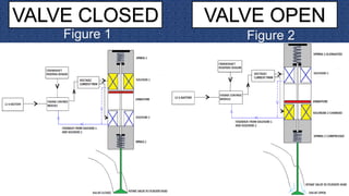
CAM-LESS ENGINES
Presentedby
Bikaskumarnishad
1601109009`
INTRODUCTION
 Various engine systems have been developed in the
effort to improve the engine performance and fuel
economy of an automobile.
 The engine will either have powerful performance or
increased fuel economy, but with the existing
technology it is difficult to achieve both
simultaneously..
 The conceptual development, design, manufacture,
and analysis of a piezoelectric controlled hydraulic
actuator. This actuator was developed for use as a
replacement for the camshaft in an internal
combustion engine, its development results in a new
device; called, the CAMLESS ENGINE (CLE).
FUNCTION OF CAM
 A cam is a mechanical member that impart
desired motions to the valves.
 As the camshaft rotates, cam lobes,
attached to the camshaft, interface with
the engine’s valves.
 This interface may take place via a
mechanical linkage, but the result is, as
the cam rotates it forces the valve open
 The spring return closes the valve when
the cam is no longer supplying the
opening force.
WORKING OF CONVENTIONAL
ENGINES
 The crankshaft turns camshaft
which operates valves by
mechanism as in figure.
 In small capacity engines cam
shafts are connected with
crankshaft by means of chain
mechanism.
 Timing of engine valves depends
on shape of cams.
The valve train in a typical internal combustion engine comprises several
moving components that are cam, camshaft, cam lobes ,poppet valves
,with valve springs.
Since the timing of engine dependent on the shape of
the cam lobes and rotational velocity of camshaft.
Considering this compromise ,automobile
manufacturers have been attempting to provide vehicles
capable of cylinder deactivation ,by variable valve
timing (VVT).
Cam less VVT allows an engine to experience
maximum engine performance and fuel efficiency at
each and every engine speed.
 This resulting design represents a compromise
between fuel efficiency and engine power.
WHAT IS CAM-LESS ENGINE
 A cam-less engine uses
electromagnetic, hydraulic, or
pneumatic actuator to open the
poppet valves.
 Actuator can be used to both
open and close the valve or an
actuator opens while spring
closes it.
 Ability to achieve truly variable
valve timing in each cycle.
CAMLESS VALVE TRAIN OPERATION
The types of camless variable valve actuating systems
being developed can be classed in two groups:
1. Electromechanical
2. Free-valve mechanism
 Sensors sense parameters from engine
& send signals to ECU
 ECU contains microprocessors with
associated software
 This ECU controls the actuators to
work according to requirements
SENSORS
ELECTRONIC
CONTROL
UNIT ACTUATORSSENSORS
SEQUENCE OF OPERATION
Electromechanical actuators
Electromechanical actuators are generally made with
two solenoids and two springs. As can be seen in fig1
the ECM( Engine control modulator) receives input
From the crankshaft position to close the valve, which
activates the solenoid1 by taking Current from battery.
The current is passed through a (pulse width modulator)
PWM ,which tunes the amplitude of the current to control
the speed of valve seating. The magnetic field created
by solenoid 1 attract the armature in the upper position.
Spring 1 is compressed and thus closes the valve.
Solenoid 2 pulls the armature down to open the valve
as shown in fig 2.
VALVE CLOSED VALVE OPEN
Figure 1 Figure 2
FREE-VALVE MECHANISM
1.Free-Valve is a mechanism which eliminates the
use of a camshaft and instead uses hydraulic and
pneumatic pressure for the actuation of valves.
2. The mechanism uses a spring return piston
cylinder arrangement which is actuated by means of
pneumatic pressure to further actuate the valves.
3.The mechanism can rapidly open a valve and hold
on for a longer duration thereby improvising the
volumetric efficiency..
DESIGN
 The Free-Valve mechanism consists of a
retraction spring, a pneumatic pressure
chamber, a hydraulic pressure chamber
and a piston to push down the valve.
 It uses lift and timing sensors to compute
the required lift and time for the valve to
stay open.
 It uses solenoids for opening hydraulic and
pneumatic valves to pressurize the
respective chambers.
 The cylinder head is designed ergonomically
to accommodate air and oil flow paths
efficiently.
 The High pressure Air solenoid and Oil check valve are
opened allowing air to enter the pneumatic chamber
and thus pushing down the Valve piston.
 Since air is compressible, the oil in the hydraulic
chamber locks the piston at the required lift. This
position is held as long as required thus, keeping the
valve open. The spring acts as a cushion to prevent
damages.
 The Low pressure air outlet solenoid and oil
outlet opens to release the pressure and the
valve piston is pushed back by the spring
force. For return cushioning, a bleed valve in
the oil chamber is also provided.
HP Oil HP air
LP air
VALVE PISTON
WORKING
WORKING
Valve Opening Valve Closing
CAM VS CAMLESS CURVE LANDING STAGE FOR CAMLESS VALVE
CURVE SHOWING LIFTING OF
VALVES AT DIFFERENT RPM
ADVANTAGES
 A Major reduction in the weight of the engine to smaller piston heads
( up to 15% less weight). Removal of timing chains and lubricating oil
supply mechanisms.
 While idling, engine can run on only two cylinders and gradual increase
In engine speed allow all cylinders to run.
 Higher response time of the valves and quicker opening this giving
more volumetric efficiency.
 Higher low end torque and total torque produced
(up to 45% more torque).
 Higher power generated without any additional
mechanisms(up to 47% more).
 Lower fuel consumption while economy is desired
(20-30% lesser fuel).
 Lower exhaust emission thus reduces Nox emissions.
DISADVANTAGES
• Hidden cost of MICROPROCESSORS &
SOFTWARE control.
• Over all cost of the system does not justify
use of commercial automobile.
• Thus may requires additional air & oil
compressors to develop pressure required for
valve actuation.
• The mechanism is not fully developed and
requires more RESEARCH .
CONCLUSION
Though various limitations arises like the cost of the
technology. But by the increased research and
technological developments, when the cost factor of CAM-
LESS heads are reduced, the mechanism will be
implemented in most of the automobiles there by
improvising the efficiency of the modern IC Engines.
THANKS

Koenigsegg cam-less engine

  • 1.
  • 2.
    INTRODUCTION  Various enginesystems have been developed in the effort to improve the engine performance and fuel economy of an automobile.  The engine will either have powerful performance or increased fuel economy, but with the existing technology it is difficult to achieve both simultaneously..  The conceptual development, design, manufacture, and analysis of a piezoelectric controlled hydraulic actuator. This actuator was developed for use as a replacement for the camshaft in an internal combustion engine, its development results in a new device; called, the CAMLESS ENGINE (CLE).
  • 3.
    FUNCTION OF CAM A cam is a mechanical member that impart desired motions to the valves.  As the camshaft rotates, cam lobes, attached to the camshaft, interface with the engine’s valves.  This interface may take place via a mechanical linkage, but the result is, as the cam rotates it forces the valve open  The spring return closes the valve when the cam is no longer supplying the opening force.
  • 4.
    WORKING OF CONVENTIONAL ENGINES The crankshaft turns camshaft which operates valves by mechanism as in figure.  In small capacity engines cam shafts are connected with crankshaft by means of chain mechanism.  Timing of engine valves depends on shape of cams.
  • 5.
    The valve trainin a typical internal combustion engine comprises several moving components that are cam, camshaft, cam lobes ,poppet valves ,with valve springs. Since the timing of engine dependent on the shape of the cam lobes and rotational velocity of camshaft. Considering this compromise ,automobile manufacturers have been attempting to provide vehicles capable of cylinder deactivation ,by variable valve timing (VVT). Cam less VVT allows an engine to experience maximum engine performance and fuel efficiency at each and every engine speed.  This resulting design represents a compromise between fuel efficiency and engine power.
  • 6.
    WHAT IS CAM-LESSENGINE  A cam-less engine uses electromagnetic, hydraulic, or pneumatic actuator to open the poppet valves.  Actuator can be used to both open and close the valve or an actuator opens while spring closes it.  Ability to achieve truly variable valve timing in each cycle.
  • 7.
    CAMLESS VALVE TRAINOPERATION The types of camless variable valve actuating systems being developed can be classed in two groups: 1. Electromechanical 2. Free-valve mechanism
  • 8.
     Sensors senseparameters from engine & send signals to ECU  ECU contains microprocessors with associated software  This ECU controls the actuators to work according to requirements SENSORS ELECTRONIC CONTROL UNIT ACTUATORSSENSORS SEQUENCE OF OPERATION
  • 9.
    Electromechanical actuators Electromechanical actuatorsare generally made with two solenoids and two springs. As can be seen in fig1 the ECM( Engine control modulator) receives input From the crankshaft position to close the valve, which activates the solenoid1 by taking Current from battery. The current is passed through a (pulse width modulator) PWM ,which tunes the amplitude of the current to control the speed of valve seating. The magnetic field created by solenoid 1 attract the armature in the upper position. Spring 1 is compressed and thus closes the valve. Solenoid 2 pulls the armature down to open the valve as shown in fig 2.
  • 10.
    VALVE CLOSED VALVEOPEN Figure 1 Figure 2
  • 11.
    FREE-VALVE MECHANISM 1.Free-Valve isa mechanism which eliminates the use of a camshaft and instead uses hydraulic and pneumatic pressure for the actuation of valves. 2. The mechanism uses a spring return piston cylinder arrangement which is actuated by means of pneumatic pressure to further actuate the valves. 3.The mechanism can rapidly open a valve and hold on for a longer duration thereby improvising the volumetric efficiency..
  • 12.
    DESIGN  The Free-Valvemechanism consists of a retraction spring, a pneumatic pressure chamber, a hydraulic pressure chamber and a piston to push down the valve.  It uses lift and timing sensors to compute the required lift and time for the valve to stay open.  It uses solenoids for opening hydraulic and pneumatic valves to pressurize the respective chambers.  The cylinder head is designed ergonomically to accommodate air and oil flow paths efficiently.
  • 13.
     The Highpressure Air solenoid and Oil check valve are opened allowing air to enter the pneumatic chamber and thus pushing down the Valve piston.  Since air is compressible, the oil in the hydraulic chamber locks the piston at the required lift. This position is held as long as required thus, keeping the valve open. The spring acts as a cushion to prevent damages.  The Low pressure air outlet solenoid and oil outlet opens to release the pressure and the valve piston is pushed back by the spring force. For return cushioning, a bleed valve in the oil chamber is also provided. HP Oil HP air LP air VALVE PISTON WORKING
  • 14.
  • 15.
    CAM VS CAMLESSCURVE LANDING STAGE FOR CAMLESS VALVE CURVE SHOWING LIFTING OF VALVES AT DIFFERENT RPM
  • 16.
    ADVANTAGES  A Majorreduction in the weight of the engine to smaller piston heads ( up to 15% less weight). Removal of timing chains and lubricating oil supply mechanisms.  While idling, engine can run on only two cylinders and gradual increase In engine speed allow all cylinders to run.  Higher response time of the valves and quicker opening this giving more volumetric efficiency.  Higher low end torque and total torque produced (up to 45% more torque).  Higher power generated without any additional mechanisms(up to 47% more).  Lower fuel consumption while economy is desired (20-30% lesser fuel).  Lower exhaust emission thus reduces Nox emissions.
  • 17.
    DISADVANTAGES • Hidden costof MICROPROCESSORS & SOFTWARE control. • Over all cost of the system does not justify use of commercial automobile. • Thus may requires additional air & oil compressors to develop pressure required for valve actuation. • The mechanism is not fully developed and requires more RESEARCH .
  • 18.
    CONCLUSION Though various limitationsarises like the cost of the technology. But by the increased research and technological developments, when the cost factor of CAM- LESS heads are reduced, the mechanism will be implemented in most of the automobiles there by improvising the efficiency of the modern IC Engines.
  • 19.