Downloaded 919 times

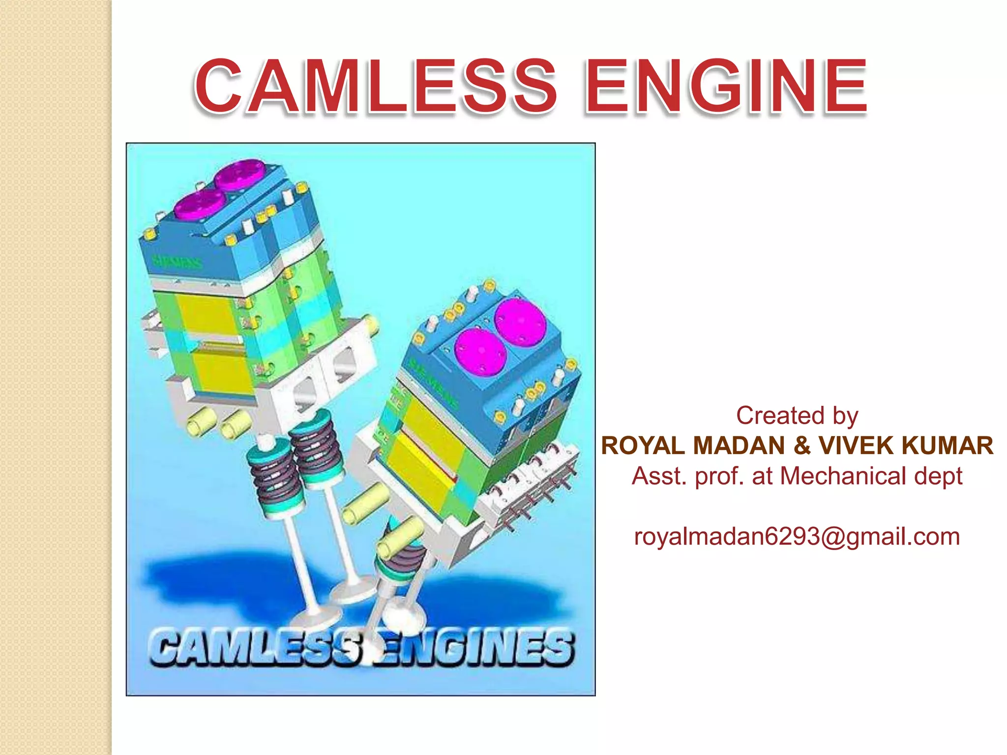
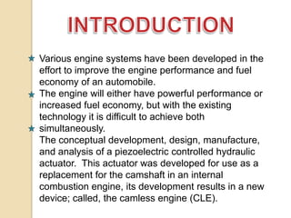
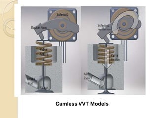
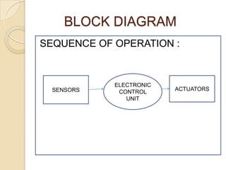
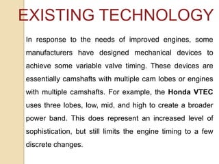
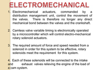

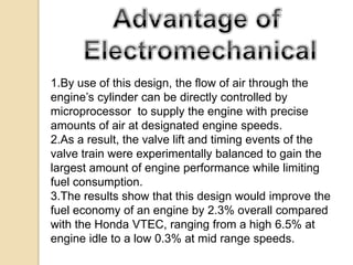
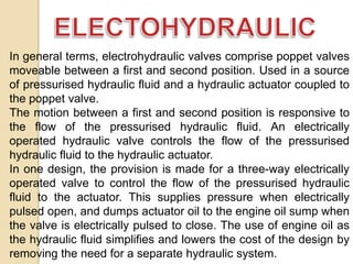
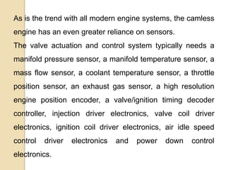
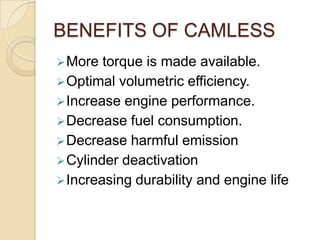
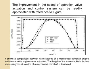
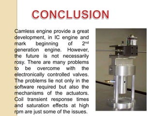


The document discusses the development and benefits of a camless engine. A camless engine uses electromagnetic, hydraulic, or pneumatic actuators instead of a camshaft to open the engine valves. This allows for truly variable valve timing in each engine cycle. The document describes two main types of camless systems - electromechanical and electrohydraulic. An electromechanical system uses solenoid actuators controlled by a microcontroller to open the valves. An electrohydraulic system uses electrically controlled hydraulic valves and actuators. Simulation results show the camless engine improves fuel economy by up to 6.5% compared to existing cam-based systems, while producing more torque.


![Just in-timeby stevespangler[1]](https://cdn.slidesharecdn.com/ss_thumbnails/just-in-timebystevespangler1-121110070309-phpapp02-thumbnail.jpg?width=640&height=640&fit=bounds)


