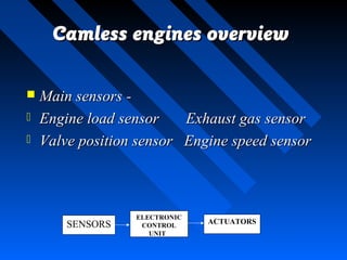
CAMLESSCAMLESS ENGINESENGINES
Presented byPresented by::
Nitesh ChowdhuryNitesh Chowdhury
IntroductionIntroduction
 CAMSCAMS
 Control the breathing channels (valves) of an ICControl the breathing channels (valves) of an IC
engineengine
 Connected to camshaft which is operated byConnected to camshaft which is operated by
crankshaftcrankshaft
 Cams push open valves at proper time & guideCams push open valves at proper time & guide
their closuretheir closure
 But they are inflexible except VTEC & VVT-IBut they are inflexible except VTEC & VVT-I
 Engineers could not vary timing, lift & duration ofEngineers could not vary timing, lift & duration of
valve opening infinitelyvalve opening infinitely
 CAMLESS ENGINESCAMLESS ENGINES
 Eliminated mechanical linkagesEliminated mechanical linkages
 Could provide infinite variation of valveCould provide infinite variation of valve
parametersparameters
 It can make engines clean, efficient &It can make engines clean, efficient &
responsiveresponsive
Working of conventionalWorking of conventional
enginesengines
 The crankshaft turns camshaft whichThe crankshaft turns camshaft which
operates valves by mechanism as in figureoperates valves by mechanism as in figure
 Spring brings back valve to initial positionSpring brings back valve to initial position
 Timing of engine valves depends on shapeTiming of engine valves depends on shape
of camsof cams
Conventional engine valvesConventional engine valves
 Engineers must design cams in theEngineers must design cams in the
development stagesdevelopment stages
 This design is compromises between engineThis design is compromises between engine
power & fuel efficiencypower & fuel efficiency
 Considering this compromise automobileConsidering this compromise automobile
companies brought variable valve timingcompanies brought variable valve timing
mechanismsmechanisms
 But its effects are limitedBut its effects are limited
Camless engines overviewCamless engines overview
 Main sensors -Main sensors -
 Engine load sensor Exhaust gas sensorEngine load sensor Exhaust gas sensor
 Valve position sensor Engine speed sensorValve position sensor Engine speed sensor
ELECTRONIC
CONTROL
UNIT
SENSORS ACTUATORS
 Sensors senseSensors sense parameters & send signals toparameters & send signals to
ECUECU
 ECU contains microprocessors withECU contains microprocessors with
associated softwareassociated software
 This ECU controls the actuators to workThis ECU controls the actuators to work
according to requirementsaccording to requirements
ActuatorsActuators
 It is a electro-hydraulic camless valve trainIt is a electro-hydraulic camless valve train
(ECV)(ECV)
 Uses elastic property of compressedUses elastic property of compressed
hydraulic fluid which acts like a liquidhydraulic fluid which acts like a liquid
spring, accelerates & decelerates the valvesspring, accelerates & decelerates the valves
 Hydraulic pendulumHydraulic pendulum
 Involves conversion of PE to KE and backInvolves conversion of PE to KE and back
to PE with minimum energy lossto PE with minimum energy loss
 During acceleration of valves PE isDuring acceleration of valves PE is
converted to KEconverted to KE
 During deceleration of valve energy ofDuring deceleration of valve energy of
moving valve is returned to fluidmoving valve is returned to fluid
Detailed view of HydraulicDetailed view of Hydraulic
PendulumPendulum
Operation of hydraulicOperation of hydraulic
pendulumpendulum
Step 1:Step 1: The solenoid valveThe solenoid valve
(high- pressure) is opened, and the(high- pressure) is opened, and the
high-pressure fluid enters thehigh-pressure fluid enters the
volume above the valve piston.volume above the valve piston.
The pressure above and below theThe pressure above and below the
piston become equal, but, becausepiston become equal, but, because
of the difference in the pressureof the difference in the pressure
areas, the constant net hydraulicareas, the constant net hydraulic
force is directed downward. Itforce is directed downward. It
opens the valve and accelerates itopens the valve and accelerates it
in the direction of opening. Thein the direction of opening. The
other solenoid valve and the twoother solenoid valve and the two
check valves remain closed.check valves remain closed.
Step 2: The opening solenoid valve closes andThe opening solenoid valve closes and
the pressure above the piston drops, but thethe pressure above the piston drops, but the
engine valve continues its downward movementengine valve continues its downward movement
due to momentum. Low-pressure check valvedue to momentum. Low-pressure check valve
opens and the volume above the piston is filledopens and the volume above the piston is filled
with the low-pressure fluid. The downwardwith the low-pressure fluid. The downward
motion of the piston pumps the high-pressuremotion of the piston pumps the high-pressure
fluid from the volume below the piston back intofluid from the volume below the piston back into
the high-pressure rail. This recovers some of thethe high-pressure rail. This recovers some of the
energy that was previously spent to accelerateenergy that was previously spent to accelerate
the valve. The ratio of the high and low-the valve. The ratio of the high and low-
pressures is selected so, that the net pressurepressures is selected so, that the net pressure
force is directed upward and the valveforce is directed upward and the valve
decelerates until it exhausts its kinetic energydecelerates until it exhausts its kinetic energy
and its motion stops. At this point, the openingand its motion stops. At this point, the opening
check valve closes, and the fluid above the pistoncheck valve closes, and the fluid above the piston
is trapped.is trapped.
This prevents the return motion of the piston, and the engine valve remains fixed inThis prevents the return motion of the piston, and the engine valve remains fixed in
its open position trapped by hydraulic pressures on both sides of the pistonits open position trapped by hydraulic pressures on both sides of the piston.
Step 3:Step 3: which is thewhich is the
open dwellopen dwell
position. Theposition. The
engine valveengine valve
remains in the openremains in the open
dwell position asdwell position as
long as necessary.long as necessary.
Step 4Step 4 illustrates the beginningillustrates the beginning
of the valve closing. The closingof the valve closing. The closing
(low-pressure) solenoid valve(low-pressure) solenoid valve
opens and connects the volumeopens and connects the volume
above the piston with the low-above the piston with the low-
pressure rail. The net pressurepressure rail. The net pressure
force is directed upward andforce is directed upward and
the engine valve accelerates inthe engine valve accelerates in
the direction of closing,the direction of closing,
pumping the fluid from thepumping the fluid from the
upper volume back into the low-upper volume back into the low-
pressure reservoir. The otherpressure reservoir. The other
solenoid valve and both checksolenoid valve and both check
valves remain closed duringvalves remain closed during
acceleration.acceleration.
Step 5Step 5 the closing solenoid valve closesthe closing solenoid valve closes
and the upper volume is disconnected fromand the upper volume is disconnected from
the low-pressure rail, but the engine valvethe low-pressure rail, but the engine valve
continues its upward motion due to itscontinues its upward motion due to its
momentum. Rising pressure in the uppermomentum. Rising pressure in the upper
volume opens the high-pressure check valvevolume opens the high-pressure check valve
that connects this volume with the high-that connects this volume with the high-
pressure reservoir. The upward motion ofpressure reservoir. The upward motion of
the valve piston pumps the fluid from thethe valve piston pumps the fluid from the
volume above the piston into the high-volume above the piston into the high-
pressure reservoir, while the increasingpressure reservoir, while the increasing
volume below the piston is filled with fluidvolume below the piston is filled with fluid
from the same reservoir. Since the changefrom the same reservoir. Since the change
of volume below the piston is only a fractionof volume below the piston is only a fraction
of that above the piston, the net flow of theof that above the piston, the net flow of the
fluid is into the high-pressure reservoir.fluid is into the high-pressure reservoir.
Again, as it was the case during the valveAgain, as it was the case during the valve
opening, energy recovery takes place.opening, energy recovery takes place.
Thus, in this system the energy recovery takes place twice each valve event.Thus, in this system the energy recovery takes place twice each valve event.
When the valve exhausts its kinetic energy, its motion stops, and the check valveWhen the valve exhausts its kinetic energy, its motion stops, and the check valve
closes.closes.
Step 6:Step 6: it illustrates the valveit illustrates the valve
seating. After that, the closingseating. After that, the closing
solenoid valve is deactivatedsolenoid valve is deactivated
again. For the rest of the cycleagain. For the rest of the cycle
both solenoid valves and bothboth solenoid valves and both
check valves are closed, thecheck valves are closed, the
pressure above the valve pistonpressure above the valve piston
is equal to the pressure in theis equal to the pressure in the
low-pressure reservoir, and thelow-pressure reservoir, and the
high pressure below the pistonhigh pressure below the piston
keeps the engine valve firmlykeeps the engine valve firmly
closed.closed.
 Lift, timing & duration of valve opening isLift, timing & duration of valve opening is
varied by controlling solenoid valvesvaried by controlling solenoid valves
 This is done by ECU when signals are sentThis is done by ECU when signals are sent
from the sensorsfrom the sensors
Modifier RodModifier Rod
 Used to impartUsed to impart
 Unequal lift to theUnequal lift to the
paired valvespaired valves
 Zero motion to anyZero motion to any
valvevalve
To enhance the ability to vary the intake air motion in theTo enhance the ability to vary the intake air motion in the
engine cylinder, it is often desirable to have unequal lift ofengine cylinder, it is often desirable to have unequal lift of
the two intake valves, or even to keep one of the two valvesthe two intake valves, or even to keep one of the two valves
closed while the other opens. In some cases it may also beclosed while the other opens. In some cases it may also be
used for paired exhaust valves. The lift modifier is then usedused for paired exhaust valves. The lift modifier is then used
to restrict the opening of one the paired valves. The modifierto restrict the opening of one the paired valves. The modifier
is shown schematically in Figure above as a Rotating rodis shown schematically in Figure above as a Rotating rod
with its axis of rotation perpendicular to the plane of thewith its axis of rotation perpendicular to the plane of the
drawing. The rod is installed in the cylinder head betweendrawing. The rod is installed in the cylinder head between
the two intake valves. A cutout in the rod forms athe two intake valves. A cutout in the rod forms a
communication chamber connected to the volumes below thecommunication chamber connected to the volumes below the
hydraulic pistons of both intake valves. The communicationhydraulic pistons of both intake valves. The communication
chamber is always connected to the high pressure reservoir.chamber is always connected to the high pressure reservoir.
Modifier Rod OperationModifier Rod Operation
In the case A theIn the case A the
modifier is in themodifier is in the
neutral position, andneutral position, and
both valves operateboth valves operate
in unisonin unison
In the case B the modifier rod is shownIn the case B the modifier rod is shown
turned 90 degrees clockwise. The exit ofturned 90 degrees clockwise. The exit of
oil from the volume below the hydraulicoil from the volume below the hydraulic
piston in the valve No. 1 is blocked andpiston in the valve No. 1 is blocked and
the valve cannot move in the direction ofthe valve cannot move in the direction of
opening. However, the entry of oil intoopening. However, the entry of oil into
the volume below the hydraulic piston isthe volume below the hydraulic piston is
permitted by a one-way valve installedpermitted by a one-way valve installed
in the modifier rod. This guaranteesin the modifier rod. This guarantees
that, whenever deactivation takes place,that, whenever deactivation takes place,
the valve No. 1 will close and remainthe valve No. 1 will close and remain
closed, while the valve No.2 continuesclosed, while the valve No.2 continues
its normal operation.its normal operation.
In the case C the lift of one of the valvesIn the case C the lift of one of the valves
is reduced relative to the second one. Theis reduced relative to the second one. The
rod is turned a smaller angle so that therod is turned a smaller angle so that the
exit of oil from the valve No. 1 into theexit of oil from the valve No. 1 into the
communication chamber is notcommunication chamber is not
completely blocked, but the flow iscompletely blocked, but the flow is
significantly throttled. As a result, thesignificantly throttled. As a result, the
motion of the valve No. 1 is slowed downmotion of the valve No. 1 is slowed down
and its lift is less than that of the valveand its lift is less than that of the valve
No.2. Varying the angular position of theNo.2. Varying the angular position of the
modifier rod 26 varies the degree of oilmodifier rod 26 varies the degree of oil
throttling, thus varying the lift of thethrottling, thus varying the lift of the
valve No. 1.valve No. 1.
AdvantagesAdvantages
 Offers continuously variable & independentOffers continuously variable & independent
control of all aspects of valve motion - lift,control of all aspects of valve motion - lift,
operation duration, event of openingoperation duration, event of opening
 ECV system can control valve velocity,ECV system can control valve velocity,
valve acceleration and decelerationvalve acceleration and deceleration
Resultant AdvantagesResultant Advantages
 Better fuel economy- 7 to 10 % increaseBetter fuel economy- 7 to 10 % increase
 Higher torque & power- 10 to 15 %Higher torque & power- 10 to 15 %
increaseincrease
 Lower exhaust emissions- EGR system isLower exhaust emissions- EGR system is
eliminated since EGR effect occurs on itseliminated since EGR effect occurs on its
own & thus reduces NOown & thus reduces NOxx emissionsemissions
 Reduction in size & weightReduction in size & weight
DisadvantagesDisadvantages
 Opening & closing of valves requires some power-Opening & closing of valves requires some power-
 Electromechanical- alternatorElectromechanical- alternator
 Electrohydraulic- accumulatorElectrohydraulic- accumulator
 Sophisticated electronic control required forSophisticated electronic control required for
gentle seating of valvesgentle seating of valves
 Current solenoids cannot run at high rpms;Current solenoids cannot run at high rpms;
 Hidden cost of microprocessor & softwareHidden cost of microprocessor & software
controlscontrols
ConclusionConclusion
Even though some disadvantages areEven though some disadvantages are
present, we can expect electro hydraulic &present, we can expect electro hydraulic &
electromechanical valves to replace theelectromechanical valves to replace the
conventional camshaft technology.conventional camshaft technology.
BIBLIOGRAPHY
 www.machinedesign.comwww.machinedesign.com
 www.diedelnet.comwww.diedelnet.com
 www.greendieseltechnology.comwww.greendieseltechnology.com
 www.techwizardz.blogspot.comwww.techwizardz.blogspot.com
ThanksThanks

CAMLESS ENGINES

  • 1.
    CAMLESSCAMLESS ENGINESENGINES Presented byPresentedby:: Nitesh ChowdhuryNitesh Chowdhury
  • 2.
    IntroductionIntroduction  CAMSCAMS  Controlthe breathing channels (valves) of an ICControl the breathing channels (valves) of an IC engineengine  Connected to camshaft which is operated byConnected to camshaft which is operated by crankshaftcrankshaft  Cams push open valves at proper time & guideCams push open valves at proper time & guide their closuretheir closure  But they are inflexible except VTEC & VVT-IBut they are inflexible except VTEC & VVT-I  Engineers could not vary timing, lift & duration ofEngineers could not vary timing, lift & duration of valve opening infinitelyvalve opening infinitely
  • 3.
     CAMLESS ENGINESCAMLESSENGINES  Eliminated mechanical linkagesEliminated mechanical linkages  Could provide infinite variation of valveCould provide infinite variation of valve parametersparameters  It can make engines clean, efficient &It can make engines clean, efficient & responsiveresponsive
  • 4.
    Working of conventionalWorkingof conventional enginesengines  The crankshaft turns camshaft whichThe crankshaft turns camshaft which operates valves by mechanism as in figureoperates valves by mechanism as in figure  Spring brings back valve to initial positionSpring brings back valve to initial position  Timing of engine valves depends on shapeTiming of engine valves depends on shape of camsof cams
  • 5.
  • 6.
     Engineers mustdesign cams in theEngineers must design cams in the development stagesdevelopment stages  This design is compromises between engineThis design is compromises between engine power & fuel efficiencypower & fuel efficiency  Considering this compromise automobileConsidering this compromise automobile companies brought variable valve timingcompanies brought variable valve timing mechanismsmechanisms  But its effects are limitedBut its effects are limited
  • 7.
    Camless engines overviewCamlessengines overview  Main sensors -Main sensors -  Engine load sensor Exhaust gas sensorEngine load sensor Exhaust gas sensor  Valve position sensor Engine speed sensorValve position sensor Engine speed sensor ELECTRONIC CONTROL UNIT SENSORS ACTUATORS
  • 8.
     Sensors senseSensorssense parameters & send signals toparameters & send signals to ECUECU  ECU contains microprocessors withECU contains microprocessors with associated softwareassociated software  This ECU controls the actuators to workThis ECU controls the actuators to work according to requirementsaccording to requirements
  • 9.
    ActuatorsActuators  It isa electro-hydraulic camless valve trainIt is a electro-hydraulic camless valve train (ECV)(ECV)  Uses elastic property of compressedUses elastic property of compressed hydraulic fluid which acts like a liquidhydraulic fluid which acts like a liquid spring, accelerates & decelerates the valvesspring, accelerates & decelerates the valves
  • 10.
     Hydraulic pendulumHydraulicpendulum  Involves conversion of PE to KE and backInvolves conversion of PE to KE and back to PE with minimum energy lossto PE with minimum energy loss  During acceleration of valves PE isDuring acceleration of valves PE is converted to KEconverted to KE  During deceleration of valve energy ofDuring deceleration of valve energy of moving valve is returned to fluidmoving valve is returned to fluid
  • 11.
    Detailed view ofHydraulicDetailed view of Hydraulic PendulumPendulum
  • 12.
    Operation of hydraulicOperationof hydraulic pendulumpendulum Step 1:Step 1: The solenoid valveThe solenoid valve (high- pressure) is opened, and the(high- pressure) is opened, and the high-pressure fluid enters thehigh-pressure fluid enters the volume above the valve piston.volume above the valve piston. The pressure above and below theThe pressure above and below the piston become equal, but, becausepiston become equal, but, because of the difference in the pressureof the difference in the pressure areas, the constant net hydraulicareas, the constant net hydraulic force is directed downward. Itforce is directed downward. It opens the valve and accelerates itopens the valve and accelerates it in the direction of opening. Thein the direction of opening. The other solenoid valve and the twoother solenoid valve and the two check valves remain closed.check valves remain closed.
  • 13.
    Step 2: Theopening solenoid valve closes andThe opening solenoid valve closes and the pressure above the piston drops, but thethe pressure above the piston drops, but the engine valve continues its downward movementengine valve continues its downward movement due to momentum. Low-pressure check valvedue to momentum. Low-pressure check valve opens and the volume above the piston is filledopens and the volume above the piston is filled with the low-pressure fluid. The downwardwith the low-pressure fluid. The downward motion of the piston pumps the high-pressuremotion of the piston pumps the high-pressure fluid from the volume below the piston back intofluid from the volume below the piston back into the high-pressure rail. This recovers some of thethe high-pressure rail. This recovers some of the energy that was previously spent to accelerateenergy that was previously spent to accelerate the valve. The ratio of the high and low-the valve. The ratio of the high and low- pressures is selected so, that the net pressurepressures is selected so, that the net pressure force is directed upward and the valveforce is directed upward and the valve decelerates until it exhausts its kinetic energydecelerates until it exhausts its kinetic energy and its motion stops. At this point, the openingand its motion stops. At this point, the opening check valve closes, and the fluid above the pistoncheck valve closes, and the fluid above the piston is trapped.is trapped. This prevents the return motion of the piston, and the engine valve remains fixed inThis prevents the return motion of the piston, and the engine valve remains fixed in its open position trapped by hydraulic pressures on both sides of the pistonits open position trapped by hydraulic pressures on both sides of the piston.
  • 14.
    Step 3:Step 3:which is thewhich is the open dwellopen dwell position. Theposition. The engine valveengine valve remains in the openremains in the open dwell position asdwell position as long as necessary.long as necessary.
  • 15.
    Step 4Step 4illustrates the beginningillustrates the beginning of the valve closing. The closingof the valve closing. The closing (low-pressure) solenoid valve(low-pressure) solenoid valve opens and connects the volumeopens and connects the volume above the piston with the low-above the piston with the low- pressure rail. The net pressurepressure rail. The net pressure force is directed upward andforce is directed upward and the engine valve accelerates inthe engine valve accelerates in the direction of closing,the direction of closing, pumping the fluid from thepumping the fluid from the upper volume back into the low-upper volume back into the low- pressure reservoir. The otherpressure reservoir. The other solenoid valve and both checksolenoid valve and both check valves remain closed duringvalves remain closed during acceleration.acceleration.
  • 16.
    Step 5Step 5the closing solenoid valve closesthe closing solenoid valve closes and the upper volume is disconnected fromand the upper volume is disconnected from the low-pressure rail, but the engine valvethe low-pressure rail, but the engine valve continues its upward motion due to itscontinues its upward motion due to its momentum. Rising pressure in the uppermomentum. Rising pressure in the upper volume opens the high-pressure check valvevolume opens the high-pressure check valve that connects this volume with the high-that connects this volume with the high- pressure reservoir. The upward motion ofpressure reservoir. The upward motion of the valve piston pumps the fluid from thethe valve piston pumps the fluid from the volume above the piston into the high-volume above the piston into the high- pressure reservoir, while the increasingpressure reservoir, while the increasing volume below the piston is filled with fluidvolume below the piston is filled with fluid from the same reservoir. Since the changefrom the same reservoir. Since the change of volume below the piston is only a fractionof volume below the piston is only a fraction of that above the piston, the net flow of theof that above the piston, the net flow of the fluid is into the high-pressure reservoir.fluid is into the high-pressure reservoir. Again, as it was the case during the valveAgain, as it was the case during the valve opening, energy recovery takes place.opening, energy recovery takes place. Thus, in this system the energy recovery takes place twice each valve event.Thus, in this system the energy recovery takes place twice each valve event. When the valve exhausts its kinetic energy, its motion stops, and the check valveWhen the valve exhausts its kinetic energy, its motion stops, and the check valve closes.closes.
  • 17.
    Step 6:Step 6:it illustrates the valveit illustrates the valve seating. After that, the closingseating. After that, the closing solenoid valve is deactivatedsolenoid valve is deactivated again. For the rest of the cycleagain. For the rest of the cycle both solenoid valves and bothboth solenoid valves and both check valves are closed, thecheck valves are closed, the pressure above the valve pistonpressure above the valve piston is equal to the pressure in theis equal to the pressure in the low-pressure reservoir, and thelow-pressure reservoir, and the high pressure below the pistonhigh pressure below the piston keeps the engine valve firmlykeeps the engine valve firmly closed.closed.
  • 18.
     Lift, timing& duration of valve opening isLift, timing & duration of valve opening is varied by controlling solenoid valvesvaried by controlling solenoid valves  This is done by ECU when signals are sentThis is done by ECU when signals are sent from the sensorsfrom the sensors
  • 19.
    Modifier RodModifier Rod Used to impartUsed to impart  Unequal lift to theUnequal lift to the paired valvespaired valves  Zero motion to anyZero motion to any valvevalve
  • 20.
    To enhance theability to vary the intake air motion in theTo enhance the ability to vary the intake air motion in the engine cylinder, it is often desirable to have unequal lift ofengine cylinder, it is often desirable to have unequal lift of the two intake valves, or even to keep one of the two valvesthe two intake valves, or even to keep one of the two valves closed while the other opens. In some cases it may also beclosed while the other opens. In some cases it may also be used for paired exhaust valves. The lift modifier is then usedused for paired exhaust valves. The lift modifier is then used to restrict the opening of one the paired valves. The modifierto restrict the opening of one the paired valves. The modifier is shown schematically in Figure above as a Rotating rodis shown schematically in Figure above as a Rotating rod with its axis of rotation perpendicular to the plane of thewith its axis of rotation perpendicular to the plane of the drawing. The rod is installed in the cylinder head betweendrawing. The rod is installed in the cylinder head between the two intake valves. A cutout in the rod forms athe two intake valves. A cutout in the rod forms a communication chamber connected to the volumes below thecommunication chamber connected to the volumes below the hydraulic pistons of both intake valves. The communicationhydraulic pistons of both intake valves. The communication chamber is always connected to the high pressure reservoir.chamber is always connected to the high pressure reservoir.
  • 21.
    Modifier Rod OperationModifierRod Operation In the case A theIn the case A the modifier is in themodifier is in the neutral position, andneutral position, and both valves operateboth valves operate in unisonin unison
  • 22.
    In the caseB the modifier rod is shownIn the case B the modifier rod is shown turned 90 degrees clockwise. The exit ofturned 90 degrees clockwise. The exit of oil from the volume below the hydraulicoil from the volume below the hydraulic piston in the valve No. 1 is blocked andpiston in the valve No. 1 is blocked and the valve cannot move in the direction ofthe valve cannot move in the direction of opening. However, the entry of oil intoopening. However, the entry of oil into the volume below the hydraulic piston isthe volume below the hydraulic piston is permitted by a one-way valve installedpermitted by a one-way valve installed in the modifier rod. This guaranteesin the modifier rod. This guarantees that, whenever deactivation takes place,that, whenever deactivation takes place, the valve No. 1 will close and remainthe valve No. 1 will close and remain closed, while the valve No.2 continuesclosed, while the valve No.2 continues its normal operation.its normal operation.
  • 23.
    In the caseC the lift of one of the valvesIn the case C the lift of one of the valves is reduced relative to the second one. Theis reduced relative to the second one. The rod is turned a smaller angle so that therod is turned a smaller angle so that the exit of oil from the valve No. 1 into theexit of oil from the valve No. 1 into the communication chamber is notcommunication chamber is not completely blocked, but the flow iscompletely blocked, but the flow is significantly throttled. As a result, thesignificantly throttled. As a result, the motion of the valve No. 1 is slowed downmotion of the valve No. 1 is slowed down and its lift is less than that of the valveand its lift is less than that of the valve No.2. Varying the angular position of theNo.2. Varying the angular position of the modifier rod 26 varies the degree of oilmodifier rod 26 varies the degree of oil throttling, thus varying the lift of thethrottling, thus varying the lift of the valve No. 1.valve No. 1.
  • 25.
    AdvantagesAdvantages  Offers continuouslyvariable & independentOffers continuously variable & independent control of all aspects of valve motion - lift,control of all aspects of valve motion - lift, operation duration, event of openingoperation duration, event of opening  ECV system can control valve velocity,ECV system can control valve velocity, valve acceleration and decelerationvalve acceleration and deceleration
  • 26.
    Resultant AdvantagesResultant Advantages Better fuel economy- 7 to 10 % increaseBetter fuel economy- 7 to 10 % increase  Higher torque & power- 10 to 15 %Higher torque & power- 10 to 15 % increaseincrease  Lower exhaust emissions- EGR system isLower exhaust emissions- EGR system is eliminated since EGR effect occurs on itseliminated since EGR effect occurs on its own & thus reduces NOown & thus reduces NOxx emissionsemissions  Reduction in size & weightReduction in size & weight
  • 27.
    DisadvantagesDisadvantages  Opening &closing of valves requires some power-Opening & closing of valves requires some power-  Electromechanical- alternatorElectromechanical- alternator  Electrohydraulic- accumulatorElectrohydraulic- accumulator  Sophisticated electronic control required forSophisticated electronic control required for gentle seating of valvesgentle seating of valves  Current solenoids cannot run at high rpms;Current solenoids cannot run at high rpms;  Hidden cost of microprocessor & softwareHidden cost of microprocessor & software controlscontrols
  • 28.
    ConclusionConclusion Even though somedisadvantages areEven though some disadvantages are present, we can expect electro hydraulic &present, we can expect electro hydraulic & electromechanical valves to replace theelectromechanical valves to replace the conventional camshaft technology.conventional camshaft technology.
  • 29.
    BIBLIOGRAPHY  www.machinedesign.comwww.machinedesign.com  www.diedelnet.comwww.diedelnet.com www.greendieseltechnology.comwww.greendieseltechnology.com  www.techwizardz.blogspot.comwww.techwizardz.blogspot.com
  • 30.