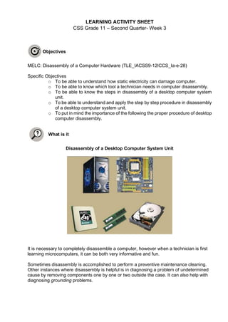
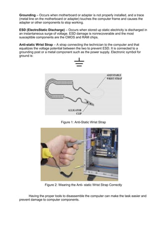
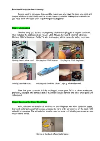
LEARNING ACTIVITY SHEET
CSS Grade 11 – Second Quarter- Week 3
Objectives
MELC: Disassembly of a Computer Hardware (TLE_IACSS9-12ICCS_Ia-e-28)
Specific Objectives
o To be able to understand how static electricity can damage computer.
o To be able to know which tool a technician needs in computer disassembly.
o To be able to know the steps in disassembly of a desktop computer system
unit.
o To be able to understand and apply the step by step procedure in disassembly
of a desktop computer system unit.
o To put in mind the importance of the following the proper procedure of desktop
computer disassembly.
What is it
Disassembly of a Desktop Computer System Unit
It is necessary to completely disassemble a computer, however when a technician is first
learning microcomputers, it can be both very informative and fun.
Sometimes disassembly is accomplished to perform a preventive maintenance cleaning.
Other instances where disassembly is helpful is in diagnosing a problem of undetermined
cause by removing components one by one or two outside the case. It can also help with
diagnosing grounding problems.
Grounding – Occurs when motherboard or adapter is not properly installed, and a trace
(metal line on the motherboard or adapter) touches the computer frame and causes the
adapter or other components to stop working.
ESD (ElectroStatic Discharge) – Occurs when stored up static electricity is discharged in
an instantaneous surge of voltage. ESD damage is nonrecoverable and the most
susceptible components are the CMOS and RAM chips.
Anti-static Wrist Strap – A strap connecting the technician to the computer and that
equalizes the voltage potential between the two to prevent ESD. It is connected to a
grounding post or a metal component such as the power supply. Electronic symbol for
ground is:
Figure 1: Anti-Static Wrist Strap
Figure 2: Wearing the Anti- static Wrist Strap Correctly
Having the proper tools to disassemble the computer can make the task easier and
prevent damage to computer components.
Personal Computer Disassembly
Before starting computer disassembly, make sure you have the tools you need and
they're all close by and handy and be sure to have a container to keep the screws in so
you have them when you want to put things back together.
Step1. Unplugging
The first thing you do is to unplug every cable that is plugged in to your computer.
That includes the cables such as Power, USB, Mouse, Keyboard, Internet, Ethernet,
Modem, AMFM Antenna, Cable TV, etc. Just unplug all the cables for safety purposes.
Unplug the monitor cord Unplug the PS/2 Mouse Unplug the PS/2 Keyboard
Unplug the USB cord Unplug the Ethernet cable Unplug the Power cord
Now that your computer is fully unplugged, move your PC to a clean workspace,
preferably a carpet. The carpet is better than tile becaus e screws and other small parts will
roll around.
Step2. Opening the Outer Shell/Case
First, unscrew the screws at the back of the computer. On most computer cases,
there will be large knobs that you can unscrew by hand or by screwdriver on the back-right
side of the computer. The left side has small screws because on that side you cannot access
much on the inside.
Screw at the back of computer case
Once the screws are removed, you can remove the side panels. On most computers,
they just slide off. Start with the left side panel (the side that once had the knobs), slide it
towards the back of the computer. Now you can remove the left panel. Just like the other
side, slide it towards the back of the computer.
Removing the side panel
Step 3: Remove Internal Cables
• Power cables are used to distribute electricity from the power supply
to the motherboard and other components.
• Data cables transmit data between the motherboard and storage
devices, such as hard drives.
• Additional cables connect the buttons and link lights on the front of the
computer case to the motherboard.
Remove Power Cables
Motherboard Power Connections
• The Advanced Technology Extended (ATX)
main power connector has either 20 or 24 pins.
The power supply may also have a 4-pin or 6-pin Auxiliary (AUX) power
connector that connects to the motherboard.
A 20-pin connector will work in a motherboard with a 24-pin socket.
SATA Molex Berg
• SATA Power Connectors use a 15-pin connector to connect to hard disk drives,
optical drives, or any devices that have a SATA power socket.
• Molex Power Connectors are used by hard disk drives and optical drives that do not
have SATA power sockets.
• CAUTION: Do not use a Molex connector and a SATA power connector on the
same drive at the same time.
• 4-pin Berg Power Connector supplies power to a floppy drive.
Remove Data Cables
PATA Cables
Drives connect to the motherboard using data cables.
• Types of data cables are:
o PATA
o SATA and
• The PATA cable (sometimes called a ribbon
cable) is wide and flat and can have either 40
or 80 conductors.
• A PATA cable usually has three 40-pin connectors.
• If multiple hard drives are installed.
• The master drive will connect to the end connector.
• The slave drive will connect to the middle connector.
• Many motherboards have two PATA cable sockets, which provides support for a
maximum of four PATA drives.
SATA Cables
The SATA data cable has a 7-pin connector.
• One end of the cable is connected to the motherboard.
• The other end is connected to any drive that has a SATA
data connector.
Remove Front Panel Connector
The front panel header
is where the
connectors of hard disk
drive activity lights,
case speaker, reset
button, power on/off
button, computer
power on light.
Step 4: Remove Internal Drives
Remove Hard Disk Drive
Drives that are installed in internal bays are called internal
drives.
• A hard disk drive (HDD) is an example of an internal
drive.
HDD removal steps:
1. Position the HDD so that it aligns with the 3.5-inch
drive bay.
2. Remove the screw in the screw holes holding down
the HDD into the drive bay.
3. Slowly pull out the HDD.
Remove Optical Drive
An optical drive is a storage device that reads and writes information to CDs or DVDs.
Optical drive removal steps:
1. Position the optical drive to align with the 5.25 inch drive bay.
2. Remove the screw in the screw holes holding down the ODD into the drive bay.
3. Slowly pull out the HDD.
Step 5: Remove the Expansion/Adapter Cards if Available
• Adapter cards are installed to add
functionality to a computer.
• Adapter cards must be compatible with
the expansion slot.
• Some adapter cards: • PCIe x1 NIC • PCI
Wireless NIC • PCIe x16 video adapter
card
Remove Video Card
• A video adapter card is the interface between a computer and a display monitor.
• An upgraded video adapter card can provide better graphic capabilities for games
and graphic programs.
Video adapter card removal steps:
1. Unscrew the mounting bracket of the case that
holds the video adapter card.
2. Pull up gently on the video adapter until it is
removed.
Step 6: Remove the Motherboard
Motherboard removal steps:
1. Untighten all the motherboard screws
which holds it to the case.
2. Hold the motherboard by the edges and
do not touch motherboard component
itself.
3. Slowly lift the motherboard out of the
frame.
Step 7: Remove the Motherboard Component
Remove Memory Card
RAM provides temporary data
storage for the CPU while the
computer is operating.
Memory Card removal steps:
1. To remove the RAM, push
down on both tabs holding
the RAM in place, which
are located at both ends of
the RAM.
2. Pull up slowly.
Remove Heat Sink/Fan
The Heat Sink/Fan Assembly is a two-part cooling device.
1. The heat sink draws heat away from the CPU.
2. The fan moves the heat away from the heat
sink.
The heat sink/fan assembly usually has a 3-pin
power connector.
Heat Sink/Fan removal steps:
1.Unplug the heat sink/fan power cable to the
header on the motherboard.
2.Loosen the heat sink/fan retainers to remove it to
its place.
3.Slowly lift up the heat sink/fan unto the CPU
socket.
Remove Central Processing Unit (CPU)
The CPU and motherboard are sensitive to electrostatic discharge
• use a grounded antistatic mat and
• wear an antistatic wrist strap.
CAUTION: When handling a CPU, do not
touch the CPU contacts.
The CPU is secured to the socket on the
motherboard with a locking assembly.
Central Processing Unit removal steps:
1. Slowly open the load lever of the
CPU socket.
2. Hold the CPU by the edges and do
not touch its plates
3. Slowly lift the CPU into its socket.
Remove Complementary Metal Oxide Semiconductor (CMOS) Battery
Small amount of memory known
as CMOS (complementary metal-
oxide- semiconductor) stores the
BIOS settings. Hardware settings,
system time and date are the parts of
BIOS settings. BIOS protect the data
each time the computer turns off. If
CMOS lose its power the system clock
resets.
CMOS Battery removal steps:
1. There is a latch used to secure battery on CMOS battery holder
2. Press the latch down by screwdriver.
3. Battery automatically pops up when the latch gets loose
Step 8: Remove Power Supply Unit
Power supply removal steps include the
following:
1.Loosen and remove the screws that hold the
PSU into its case.
2. Lift up the PSU out from its case
Step 9: Remove IO Shield
1. Shield to keep electro-magnetic radiation
inside of the case
2. Dust Cover / Air circulation director: The
fan in the power supply shall draw air
throughout the entire case and not just
along the short way from the I/O area to the power supply that is usually right
above.
3. Aesthetics: No ugly hole.
IOS Shield removal steps:
1. Push out the IO Shield along its computer case.
Activity
Activity 1: Multiple Choice: Write your answer in separate sheet.
1. Occurs when motherboard or adapter is not properly installed, and a trace (metal
line on the motherboard or adapter) touches the computer frame and causes the
adapter or other components to stop working
a. Electrocution b. Discharge c. Grounding d. Damage
2. Occurs when stored up static electricity is discharged in an instantaneous surge of
voltage.
a. Electrocution b. Discharge c. Grounding d. Damage
3. A strap connecting the technician to the computer and that equalizes the voltage
potential between the two to prevent ESD.
a. Anti-static mat b. Anti-static wrist strap c. Screwdriver d. Cable ties
4. Are used to distribute electricity from the power supply to the motherboard and
other components.
a. Power cables b. Data cables c. Motherboard d. Hard Disk
5. Transmit data between the motherboard and storage devices, such as hard drives
a. Power cables b. Data cables c. Motherboard d. Hard Disk
6. How many ports does Advanced Technology Extended (ATX) main power
connector have?
a. 21 to 23 b. 20-23 c. 20-24 d. 21-24
7. How many pins does SATA connector have?
a. 9 b. 7 c. 5 d. 8
8. Drives that are installed in internal bays are called.
a. External drives b. Outer drives c. Internal drives d. Rear drives
9. Is a storage device that reads and writes information to CDs or DVDs?
a. Hard Disk Drive b. Memory Card c. Front Panel d. Optical Drive
10.Stores the BIOS settings, hardware settings, system time and date that are the part
of the BIOS settings.
a. Memory b. CMOS c. Front Panel d. Optical Drive
Activity 2: Rearrange the following procedures in their proper order. Use numbers to
indicate their order of precedence.
_____ 1. Remove the motherboard
_____ 2. Remove the power supply unit
_____ 3. Remove the expansion card/adapter
_____ 4. Remove the internal drives
_____ 5. Remove the IO Shield
_____ 6. Remove the internal cables
_____ 7. Remove the motherboard components
_____ 8. Unplugging
_____ 9. Remove the outer shell/case.
Activity 3: Direction: Answer the essential questions below according to your experience in
connecting hardware and peripherals of a computer.
1. What is the essence of following the correct procedures in disassembling the PC parts?
2. What is your perspective why the IO Shield should always be the last on the procedure
in desktop computer disassembling?
3. What do you feel when you are doing the activity?
4. As a computer technician, why do think skills is a crucial factor?
Answer key
Activity 1
1. C
2. B
3. B
4. A
5. B
6. C
7. B
8. C
9. D
10. B
Activity 2
___6__ 1. Remove the motherboard
___8__ 2. Remove the power supply unit
___5__ 3. Remove the expansion card/adapter
___4__ 4. Remove the internal drives
___9__ 5. Remove the IO Shield
___3__ 6. Remove the internal cables
___7__ 7. Remove the motherboard components
___1__ 8. Unplugging
___2__ 9. Remove the outer shell/case.
Activity 3
Prepared by:
DANILO B. AÑOS
Teacher II/ Barobo NHS

Css grade 11 week 3

  • 1.
    LEARNING ACTIVITY SHEET CSSGrade 11 – Second Quarter- Week 3 Objectives MELC: Disassembly of a Computer Hardware (TLE_IACSS9-12ICCS_Ia-e-28) Specific Objectives o To be able to understand how static electricity can damage computer. o To be able to know which tool a technician needs in computer disassembly. o To be able to know the steps in disassembly of a desktop computer system unit. o To be able to understand and apply the step by step procedure in disassembly of a desktop computer system unit. o To put in mind the importance of the following the proper procedure of desktop computer disassembly. What is it Disassembly of a Desktop Computer System Unit It is necessary to completely disassemble a computer, however when a technician is first learning microcomputers, it can be both very informative and fun. Sometimes disassembly is accomplished to perform a preventive maintenance cleaning. Other instances where disassembly is helpful is in diagnosing a problem of undetermined cause by removing components one by one or two outside the case. It can also help with diagnosing grounding problems.
  • 2.
    Grounding – Occurswhen motherboard or adapter is not properly installed, and a trace (metal line on the motherboard or adapter) touches the computer frame and causes the adapter or other components to stop working. ESD (ElectroStatic Discharge) – Occurs when stored up static electricity is discharged in an instantaneous surge of voltage. ESD damage is nonrecoverable and the most susceptible components are the CMOS and RAM chips. Anti-static Wrist Strap – A strap connecting the technician to the computer and that equalizes the voltage potential between the two to prevent ESD. It is connected to a grounding post or a metal component such as the power supply. Electronic symbol for ground is: Figure 1: Anti-Static Wrist Strap Figure 2: Wearing the Anti- static Wrist Strap Correctly Having the proper tools to disassemble the computer can make the task easier and prevent damage to computer components.
  • 3.
    Personal Computer Disassembly Beforestarting computer disassembly, make sure you have the tools you need and they're all close by and handy and be sure to have a container to keep the screws in so you have them when you want to put things back together. Step1. Unplugging The first thing you do is to unplug every cable that is plugged in to your computer. That includes the cables such as Power, USB, Mouse, Keyboard, Internet, Ethernet, Modem, AMFM Antenna, Cable TV, etc. Just unplug all the cables for safety purposes. Unplug the monitor cord Unplug the PS/2 Mouse Unplug the PS/2 Keyboard Unplug the USB cord Unplug the Ethernet cable Unplug the Power cord Now that your computer is fully unplugged, move your PC to a clean workspace, preferably a carpet. The carpet is better than tile becaus e screws and other small parts will roll around. Step2. Opening the Outer Shell/Case First, unscrew the screws at the back of the computer. On most computer cases, there will be large knobs that you can unscrew by hand or by screwdriver on the back-right side of the computer. The left side has small screws because on that side you cannot access much on the inside. Screw at the back of computer case
  • 4.
    Once the screwsare removed, you can remove the side panels. On most computers, they just slide off. Start with the left side panel (the side that once had the knobs), slide it towards the back of the computer. Now you can remove the left panel. Just like the other side, slide it towards the back of the computer. Removing the side panel Step 3: Remove Internal Cables • Power cables are used to distribute electricity from the power supply to the motherboard and other components. • Data cables transmit data between the motherboard and storage devices, such as hard drives. • Additional cables connect the buttons and link lights on the front of the computer case to the motherboard. Remove Power Cables Motherboard Power Connections • The Advanced Technology Extended (ATX) main power connector has either 20 or 24 pins. The power supply may also have a 4-pin or 6-pin Auxiliary (AUX) power connector that connects to the motherboard. A 20-pin connector will work in a motherboard with a 24-pin socket.
  • 5.
    SATA Molex Berg •SATA Power Connectors use a 15-pin connector to connect to hard disk drives, optical drives, or any devices that have a SATA power socket. • Molex Power Connectors are used by hard disk drives and optical drives that do not have SATA power sockets. • CAUTION: Do not use a Molex connector and a SATA power connector on the same drive at the same time. • 4-pin Berg Power Connector supplies power to a floppy drive. Remove Data Cables PATA Cables Drives connect to the motherboard using data cables. • Types of data cables are: o PATA o SATA and • The PATA cable (sometimes called a ribbon cable) is wide and flat and can have either 40 or 80 conductors. • A PATA cable usually has three 40-pin connectors. • If multiple hard drives are installed. • The master drive will connect to the end connector. • The slave drive will connect to the middle connector. • Many motherboards have two PATA cable sockets, which provides support for a maximum of four PATA drives. SATA Cables The SATA data cable has a 7-pin connector. • One end of the cable is connected to the motherboard. • The other end is connected to any drive that has a SATA data connector.
  • 6.
    Remove Front PanelConnector The front panel header is where the connectors of hard disk drive activity lights, case speaker, reset button, power on/off button, computer power on light. Step 4: Remove Internal Drives Remove Hard Disk Drive Drives that are installed in internal bays are called internal drives. • A hard disk drive (HDD) is an example of an internal drive. HDD removal steps: 1. Position the HDD so that it aligns with the 3.5-inch drive bay. 2. Remove the screw in the screw holes holding down the HDD into the drive bay. 3. Slowly pull out the HDD. Remove Optical Drive An optical drive is a storage device that reads and writes information to CDs or DVDs. Optical drive removal steps: 1. Position the optical drive to align with the 5.25 inch drive bay. 2. Remove the screw in the screw holes holding down the ODD into the drive bay. 3. Slowly pull out the HDD.
  • 7.
    Step 5: Removethe Expansion/Adapter Cards if Available • Adapter cards are installed to add functionality to a computer. • Adapter cards must be compatible with the expansion slot. • Some adapter cards: • PCIe x1 NIC • PCI Wireless NIC • PCIe x16 video adapter card Remove Video Card • A video adapter card is the interface between a computer and a display monitor. • An upgraded video adapter card can provide better graphic capabilities for games and graphic programs. Video adapter card removal steps: 1. Unscrew the mounting bracket of the case that holds the video adapter card. 2. Pull up gently on the video adapter until it is removed. Step 6: Remove the Motherboard Motherboard removal steps: 1. Untighten all the motherboard screws which holds it to the case. 2. Hold the motherboard by the edges and do not touch motherboard component itself. 3. Slowly lift the motherboard out of the frame. Step 7: Remove the Motherboard Component Remove Memory Card RAM provides temporary data storage for the CPU while the computer is operating. Memory Card removal steps: 1. To remove the RAM, push down on both tabs holding the RAM in place, which are located at both ends of the RAM. 2. Pull up slowly.
  • 8.
    Remove Heat Sink/Fan TheHeat Sink/Fan Assembly is a two-part cooling device. 1. The heat sink draws heat away from the CPU. 2. The fan moves the heat away from the heat sink. The heat sink/fan assembly usually has a 3-pin power connector. Heat Sink/Fan removal steps: 1.Unplug the heat sink/fan power cable to the header on the motherboard. 2.Loosen the heat sink/fan retainers to remove it to its place. 3.Slowly lift up the heat sink/fan unto the CPU socket. Remove Central Processing Unit (CPU) The CPU and motherboard are sensitive to electrostatic discharge • use a grounded antistatic mat and • wear an antistatic wrist strap. CAUTION: When handling a CPU, do not touch the CPU contacts. The CPU is secured to the socket on the motherboard with a locking assembly. Central Processing Unit removal steps: 1. Slowly open the load lever of the CPU socket. 2. Hold the CPU by the edges and do not touch its plates 3. Slowly lift the CPU into its socket. Remove Complementary Metal Oxide Semiconductor (CMOS) Battery Small amount of memory known as CMOS (complementary metal- oxide- semiconductor) stores the BIOS settings. Hardware settings, system time and date are the parts of BIOS settings. BIOS protect the data each time the computer turns off. If CMOS lose its power the system clock resets. CMOS Battery removal steps: 1. There is a latch used to secure battery on CMOS battery holder 2. Press the latch down by screwdriver. 3. Battery automatically pops up when the latch gets loose
  • 9.
    Step 8: RemovePower Supply Unit Power supply removal steps include the following: 1.Loosen and remove the screws that hold the PSU into its case. 2. Lift up the PSU out from its case Step 9: Remove IO Shield 1. Shield to keep electro-magnetic radiation inside of the case 2. Dust Cover / Air circulation director: The fan in the power supply shall draw air throughout the entire case and not just along the short way from the I/O area to the power supply that is usually right above. 3. Aesthetics: No ugly hole. IOS Shield removal steps: 1. Push out the IO Shield along its computer case. Activity Activity 1: Multiple Choice: Write your answer in separate sheet. 1. Occurs when motherboard or adapter is not properly installed, and a trace (metal line on the motherboard or adapter) touches the computer frame and causes the adapter or other components to stop working a. Electrocution b. Discharge c. Grounding d. Damage 2. Occurs when stored up static electricity is discharged in an instantaneous surge of voltage. a. Electrocution b. Discharge c. Grounding d. Damage 3. A strap connecting the technician to the computer and that equalizes the voltage potential between the two to prevent ESD. a. Anti-static mat b. Anti-static wrist strap c. Screwdriver d. Cable ties 4. Are used to distribute electricity from the power supply to the motherboard and other components. a. Power cables b. Data cables c. Motherboard d. Hard Disk 5. Transmit data between the motherboard and storage devices, such as hard drives a. Power cables b. Data cables c. Motherboard d. Hard Disk
  • 10.
    6. How manyports does Advanced Technology Extended (ATX) main power connector have? a. 21 to 23 b. 20-23 c. 20-24 d. 21-24 7. How many pins does SATA connector have? a. 9 b. 7 c. 5 d. 8 8. Drives that are installed in internal bays are called. a. External drives b. Outer drives c. Internal drives d. Rear drives 9. Is a storage device that reads and writes information to CDs or DVDs? a. Hard Disk Drive b. Memory Card c. Front Panel d. Optical Drive 10.Stores the BIOS settings, hardware settings, system time and date that are the part of the BIOS settings. a. Memory b. CMOS c. Front Panel d. Optical Drive Activity 2: Rearrange the following procedures in their proper order. Use numbers to indicate their order of precedence. _____ 1. Remove the motherboard _____ 2. Remove the power supply unit _____ 3. Remove the expansion card/adapter _____ 4. Remove the internal drives _____ 5. Remove the IO Shield _____ 6. Remove the internal cables _____ 7. Remove the motherboard components _____ 8. Unplugging _____ 9. Remove the outer shell/case. Activity 3: Direction: Answer the essential questions below according to your experience in connecting hardware and peripherals of a computer. 1. What is the essence of following the correct procedures in disassembling the PC parts? 2. What is your perspective why the IO Shield should always be the last on the procedure in desktop computer disassembling? 3. What do you feel when you are doing the activity? 4. As a computer technician, why do think skills is a crucial factor?
  • 11.
    Answer key Activity 1 1.C 2. B 3. B 4. A 5. B 6. C 7. B 8. C 9. D 10. B Activity 2 ___6__ 1. Remove the motherboard ___8__ 2. Remove the power supply unit ___5__ 3. Remove the expansion card/adapter ___4__ 4. Remove the internal drives ___9__ 5. Remove the IO Shield ___3__ 6. Remove the internal cables ___7__ 7. Remove the motherboard components ___1__ 8. Unplugging ___2__ 9. Remove the outer shell/case. Activity 3 Prepared by: DANILO B. AÑOS Teacher II/ Barobo NHS