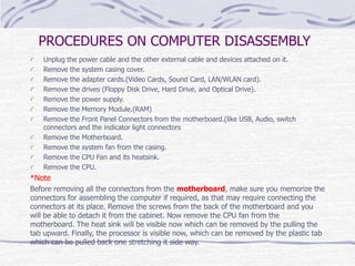
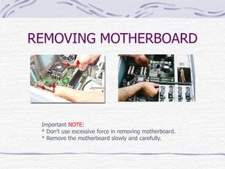
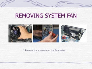
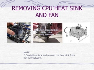
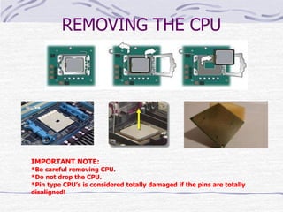
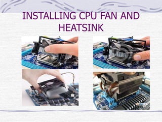
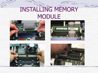
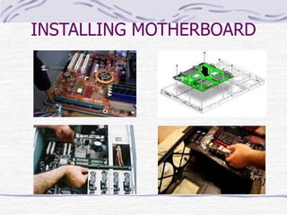
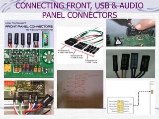
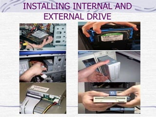
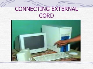
COMPUTER
ASSEMBLY AND DISASSEMBLY
PROCEDURE AND SAFETY
PRECAUTIONS
OVERVIEW OF SYSTEM UNIT
PARTS
SYSTEM CASING
MOTHERBOARD
CPU
LAN CARD/WLAN CARD
GRAPHICS CARD/VIDEO CARD
RAM (Random Access Memory)
POWER SUPPLY
SYSTEM FAN(Chassis Fan)
HARD DRIVE
OPTICAL DRIVE (CD Rom)
CPU FAN AND HEAT SINK
FLOPPY DRIVE
IDE CABLE
SATA CABLE
MOTHERBOARD I/O SHIELD
SYSTEM CASING CABLE HEADERS
* FRONT USB CONNECTORS
* FRONT PANEL CONNECTORS
* FRONT AUDIO CONNECTORS
SAFETY PRECAUTION IN
DISASSEMBLY/ASSEMBLING SYSTEM
UNIT:
Always power off and unplug the computer before working on it.
Before touching parts of system unit, you must discharge or ground yourself to avoid the
components from damaging caused by Electro Static Discharge or ESD.
Take away any liquid such as mineral water or soft drinks near your working area or near
computers.
Hold the components by edges and do not touch the IC’s.
When removing power cables from the motherboard like ATX, SATA, Legacy power cord,
Always full the cable connector on the handle, not on the cable itself.
Personal protective equipment must be correctly used.
Be careful with the tools that may cause short circuit
Make sure that the pins are properly aligned when connecting a cable connector
Read and follow instruction on the manual carefully.
Do not use excessive force if things don’t quite slip into place.
PROCEDURES ON COMPUTER DISASSEMBLY
Unplug the power cable and the other external cable and devices attached on it.
Remove the system casing cover.
Remove the adapter cards.(Video Cards, Sound Card, LAN/WLAN card).
Remove the drives (Floppy Disk Drive, Hard Drive, and Optical Drive).
Remove the power supply.
Remove the Memory Module.(RAM)
Remove the Front Panel Connectors from the motherboard.(like USB, Audio, switch
connectors and the indicator light connectors
Remove the Motherboard.
Remove the system fan from the casing.
Remove the CPU Fan and its heatsink.
Remove the CPU.
*Note
Before removing all the connectors from the motherboard, make sure you memorize the
connectors for assembling the computer if required, as that may require connecting the
connectors at its place. Remove the screws from the back of the motherboard and you
will be able to detach it from the cabinet. Now remove the CPU fan from the
motherboard. The heat sink will be visible now which can be removed by the pulling the
tab upward. Finally, the processor is visible now, which can be removed by the plastic tab
which can be pulled back one stretching it side way.
ACTUAL PICTURES OF
COMPUTER DISASSEMBLY:
REMOVING SYSTEM CASING COVER
REMOVING ADAPTER CARDS
*Video Card
*Audio Card
*Network Card (LAN/WLAN)
REMOVING
INTERNAL/EXTERNAL DRIVES
*Floppy Disk Drive
*Hard Disk Drive
*Optical Disk Drive
NOTE:
* To remove the drives from system chassis, you must remove all
of the screw to its side..
REMOVING POWER SUPPLY
UNIT
*Remove the screws from the four sides.
REMOVING MEMORY MODULE
(RAM)
To remove the RAM, Press the lock on both side. RAM will
automatically released.
REMOVING FRONT PANEL
CONNECTORS
Note:
* Some of the cables are already keyed.
* When Removing front panel connectors, memorize it or you can label it on
scratch paper. MISTAKES CAN CAUSE MOTHERBOARD DAMAGE!!
REMOVING MOTHERBOARD
Important NOTE:
* Don’t use excessive force in removing motherboard.
* Remove the motherboard slowly and carefully.
REMOVING SYSTEM FAN
* Remove the screws from the four sides.
REMOVING CPU HEAT SINK
AND FAN
NOTE:
* Carefully unlock and remove the heat sink from
the motherboard.
REMOVING THE CPU
IMPORTANT NOTE:
*Be careful removing CPU.
*Do not drop the CPU.
*Pin type CPU’s is considered totally damaged if the pins are totally
disaligned!
PROCEDURES ON COMPUTER ASSEMBLING
Prepare the system chassis, install the power supply unit, I/O shield (“Back Plate of the
motherboard”), system fan and the motherboard spacers.
Install the CPU on the Motherboard. Make sure that CPU is facing the correct position on
the socket.
Apply thermal paste to the CPU.
Install the CPU Fan and the Heatsink.
Install the Memory Module (RAM) to the Motherboard.
Install the motherboard to the system chassis and secure it with the screws per side.
Connect The Chassis Fan & Power Connectors (ATX 4 Pin & ATX 24 Pin) to the
motherboard
Connect the Front Panel Connectors to the motherboard (Front USB, Front Audio, Reset
Switch, Power Switch and the indicator lights.
Install the internal and external drive ( Hard Disk Drive, Floppy Drive & the Optical Disk
Drive.
Connect the power cords and the drive cables to the drives (SATA Cable, IDE Cable, Floppy
Drive Cable, SATA power cord and the legacy power cord.)
Install the Adapter Cards (Video Card, Sound Card, Network Card Such as LAN and WLAN
card) and secure it with screws.
Connect the External cords and Devices (VGA, Power cord, keyboard, mouse and the
network cable.)
Troubleshoot if necessary.
ACTUAL PICTURES OF
ASSEMBLY:
SYSTEM CASE PREPARATION
Installing CPU on the Motherboard
APPLYING THERMAL PASTE ON THE
CPU
INSTALLING CPU FAN AND
HEATSINK
INSTALLING MEMORY
MODULE
INSTALLING MOTHERBOARD
CONNECTING CHASSIS FAN, ATX
4 & 24 PIN POWER CORD
CONNECTING FRONT, USB & AUDIO
PANEL CONNECTORS
INSTALLING INTERNAL AND
EXTERNAL DRIVE
CONNECTING POWER AND
DATA CABLE TO DRIVES
INSTALLING ADAPTER CARDS:
(VIDEO, AUDIO & NETWORK CARDS)
CONNECTING EXTERNAL
CORD
THANKS FOR VIEWING 
PREPARED BY:
Lourent Villy V. Conlu

381402142-Disassembling-System-Unit-Procedure-and-Safety-Precautions.pptx

  • 1.
  • 2.
    OVERVIEW OF SYSTEMUNIT PARTS SYSTEM CASING MOTHERBOARD CPU LAN CARD/WLAN CARD GRAPHICS CARD/VIDEO CARD RAM (Random Access Memory) POWER SUPPLY SYSTEM FAN(Chassis Fan) HARD DRIVE OPTICAL DRIVE (CD Rom) CPU FAN AND HEAT SINK FLOPPY DRIVE IDE CABLE SATA CABLE MOTHERBOARD I/O SHIELD SYSTEM CASING CABLE HEADERS * FRONT USB CONNECTORS * FRONT PANEL CONNECTORS * FRONT AUDIO CONNECTORS
  • 3.
    SAFETY PRECAUTION IN DISASSEMBLY/ASSEMBLINGSYSTEM UNIT: Always power off and unplug the computer before working on it. Before touching parts of system unit, you must discharge or ground yourself to avoid the components from damaging caused by Electro Static Discharge or ESD. Take away any liquid such as mineral water or soft drinks near your working area or near computers. Hold the components by edges and do not touch the IC’s. When removing power cables from the motherboard like ATX, SATA, Legacy power cord, Always full the cable connector on the handle, not on the cable itself. Personal protective equipment must be correctly used. Be careful with the tools that may cause short circuit Make sure that the pins are properly aligned when connecting a cable connector Read and follow instruction on the manual carefully. Do not use excessive force if things don’t quite slip into place.
  • 4.
    PROCEDURES ON COMPUTERDISASSEMBLY Unplug the power cable and the other external cable and devices attached on it. Remove the system casing cover. Remove the adapter cards.(Video Cards, Sound Card, LAN/WLAN card). Remove the drives (Floppy Disk Drive, Hard Drive, and Optical Drive). Remove the power supply. Remove the Memory Module.(RAM) Remove the Front Panel Connectors from the motherboard.(like USB, Audio, switch connectors and the indicator light connectors Remove the Motherboard. Remove the system fan from the casing. Remove the CPU Fan and its heatsink. Remove the CPU. *Note Before removing all the connectors from the motherboard, make sure you memorize the connectors for assembling the computer if required, as that may require connecting the connectors at its place. Remove the screws from the back of the motherboard and you will be able to detach it from the cabinet. Now remove the CPU fan from the motherboard. The heat sink will be visible now which can be removed by the pulling the tab upward. Finally, the processor is visible now, which can be removed by the plastic tab which can be pulled back one stretching it side way.
  • 5.
    ACTUAL PICTURES OF COMPUTERDISASSEMBLY: REMOVING SYSTEM CASING COVER
  • 6.
    REMOVING ADAPTER CARDS *VideoCard *Audio Card *Network Card (LAN/WLAN)
  • 7.
    REMOVING INTERNAL/EXTERNAL DRIVES *Floppy DiskDrive *Hard Disk Drive *Optical Disk Drive NOTE: * To remove the drives from system chassis, you must remove all of the screw to its side..
  • 8.
    REMOVING POWER SUPPLY UNIT *Removethe screws from the four sides.
  • 9.
    REMOVING MEMORY MODULE (RAM) Toremove the RAM, Press the lock on both side. RAM will automatically released.
  • 10.
    REMOVING FRONT PANEL CONNECTORS Note: *Some of the cables are already keyed. * When Removing front panel connectors, memorize it or you can label it on scratch paper. MISTAKES CAN CAUSE MOTHERBOARD DAMAGE!!
  • 11.
    REMOVING MOTHERBOARD Important NOTE: *Don’t use excessive force in removing motherboard. * Remove the motherboard slowly and carefully.
  • 12.
    REMOVING SYSTEM FAN *Remove the screws from the four sides.
  • 13.
    REMOVING CPU HEATSINK AND FAN NOTE: * Carefully unlock and remove the heat sink from the motherboard.
  • 14.
    REMOVING THE CPU IMPORTANTNOTE: *Be careful removing CPU. *Do not drop the CPU. *Pin type CPU’s is considered totally damaged if the pins are totally disaligned!
  • 15.
    PROCEDURES ON COMPUTERASSEMBLING Prepare the system chassis, install the power supply unit, I/O shield (“Back Plate of the motherboard”), system fan and the motherboard spacers. Install the CPU on the Motherboard. Make sure that CPU is facing the correct position on the socket. Apply thermal paste to the CPU. Install the CPU Fan and the Heatsink. Install the Memory Module (RAM) to the Motherboard. Install the motherboard to the system chassis and secure it with the screws per side. Connect The Chassis Fan & Power Connectors (ATX 4 Pin & ATX 24 Pin) to the motherboard Connect the Front Panel Connectors to the motherboard (Front USB, Front Audio, Reset Switch, Power Switch and the indicator lights. Install the internal and external drive ( Hard Disk Drive, Floppy Drive & the Optical Disk Drive. Connect the power cords and the drive cables to the drives (SATA Cable, IDE Cable, Floppy Drive Cable, SATA power cord and the legacy power cord.) Install the Adapter Cards (Video Card, Sound Card, Network Card Such as LAN and WLAN card) and secure it with screws. Connect the External cords and Devices (VGA, Power cord, keyboard, mouse and the network cable.) Troubleshoot if necessary.
  • 16.
  • 17.
    Installing CPU onthe Motherboard
  • 18.
  • 19.
    INSTALLING CPU FANAND HEATSINK
  • 20.
  • 21.
  • 22.
    CONNECTING CHASSIS FAN,ATX 4 & 24 PIN POWER CORD
  • 23.
    CONNECTING FRONT, USB& AUDIO PANEL CONNECTORS
  • 24.
  • 25.
  • 26.
    INSTALLING ADAPTER CARDS: (VIDEO,AUDIO & NETWORK CARDS)
  • 27.
  • 28.
    THANKS FOR VIEWING PREPARED BY: Lourent Villy V. Conlu