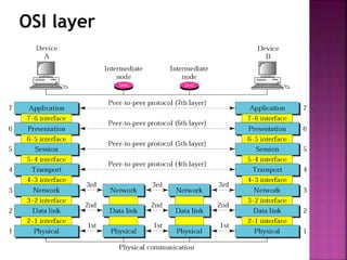
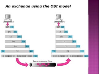
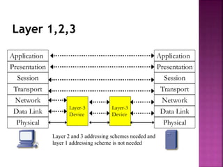
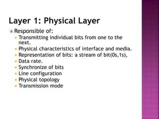
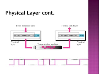
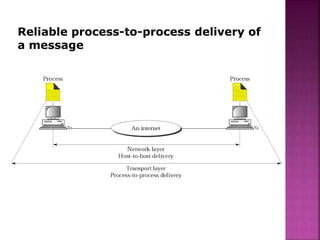
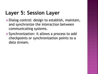
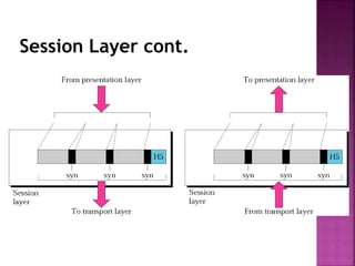
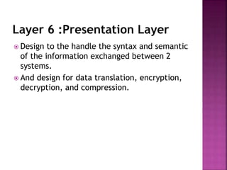
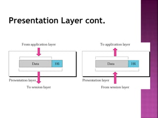
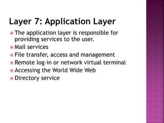
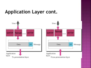
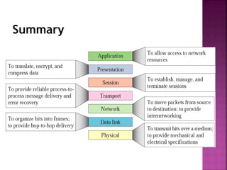
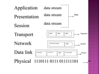
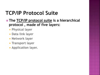
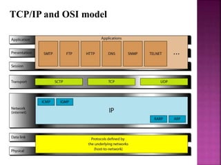
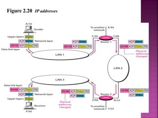
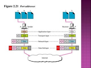
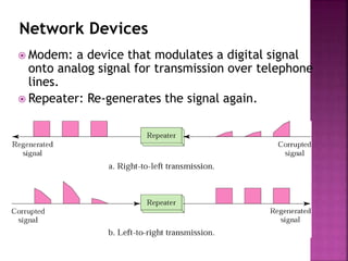
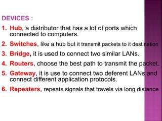
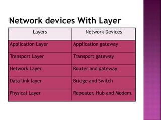
Lecturer: MOHAMMAD NAZIR
Data
Communication
Data Communications and
Networking, 4rd Edition, Behrouz A.
Forouzan
Chapter 2: Network Models
The OSI Model
 Open Systems Interconnection (OSI).
 Developed by the International Organization for
Standardization (ISO).
 Model for understanding and developing computer-
to-computer communication architecture that is
flexible, robust and interoperable.
 It is not a protocol.
 Developed in the 1980s.
 Divides network architecture into seven layers.
OSI cont.
 Each layer performs a subset of the required communication
functions
 Each layer relies on the next lower layer to perform more
primitive functions
 Each layer provides services to the next higher layer
 Changes in one layer should not require changes in other
layers
 Layer 1,2,3 are the network support layer, deals with the
physical aspects of moving data from one device to another.
 Layer 5,6,7 are the user support layer, allow the
interoperability among unrelated software.
 Layer 4 ensures that what the lower layer have transmitted
is in a form that the upper layers can use.
OSI layer
 Application layer
 Presentation layer
 Session layer
 Transport layer
 Network layer
 Data Link layer
 Physical layer
OSI layer
An exchange using the OSI model
Layer 1,2,3
Application
Presentation
Session
Transport
Network
Data Link
Physical
Application
Presentation
Session
Transport
Network
Data Link
Physical
Layer-3
Device
Layer-3
Device
Layer 2 and 3 addressing schemes needed and
layer 1 addressing scheme is not needed
Layer 1: Physical Layer
 Responsible of:
 Transmitting individual bits from one to the
next.
 Physical characteristics of interface and media.
 Representation of bits: a stream of bit(0s,1s),
 Data rate.
 Synchronize of bits
 Line configuration
 Physical topology
 Transmission mode
Physical Layer cont.
Layer 2: Data Link layer
 Responsible of:
 Moving frames from one hop (node) to the next.
 Framing: divided the stream of bits received from
the network layer manageable data units called
frames.
 Physical address (MAC address).
 Flow control.
 Error control: added trailer to the end of frame.
 Access control.
 Hop to hop delivery
Data Link layer cont.
10110110101 01100010011 10110000001
Hop-to-Hop delivery
Layer 3: Network Layer
 The network layer is responsible:
 The delivery of individual packets from the
original source to the final destination .
 Logical addressing: if the packet passes the
network boundary we need another addressing
system to help (source to destination) connection.
 Routing : route or switch the packet to final
destination.
 Source-to-destination delivery (End-to-End).
Network Layer cont.
Source-to-Destination delivery
Layer 4: Transport Layer
 The transport layer is responsible for:
 Service point or Port addressing
 Segmentation and reassembly : a message is
divided into transmittable segments each segment
containing a sequence no.
 Connection Control: connection oriented or
connectionless.
 Flow control
 Error control
Transport Layer cont.
Reliable process-to-process delivery of
a message
Layer 5: Session Layer
 Dialog control: design to establish, maintain,
and synchronize the interaction between
communicating systems.
 Synchronization: it allows a process to add
checkpoints or synchronization points to a
data stream.
Session Layer cont.
Layer 6 :Presentation Layer
 Design to the handle the syntax and semantic
of the information exchanged between 2
systems.
 And design for data translation, encryption,
decryption, and compression.
Presentation Layer cont.
Layer 7: Application Layer
 The application layer is responsible for
providing services to the user.
 Mail services
 File transfer, access and management
 Remote log-in or network virtual terminal
 Accessing the World Wide Web
 Directory service
Application Layer cont.
HTTP
Telnet
SMTPHTTPTelnetSMTP
Summary
data
data data data
Network header data
Frame H Network H data
Segments
packets
Frames
Bits
From trailer
data stream
data stream
data stream
Application
Presentation
Session
Transport
Network
Data link
Physical 1110111 0111 011111101
data
data data data
Network header data
Frame H Network H data
Segments
packets
Frames
Bits
From trailer
data stream
data stream
data stream
Application
Presentation
Session
Transport
Network
Data link
Physical 1110111 0111 011111101
TCP/IP Protocol Suite
 The TCP/IP protocol suite is a hierarchical
protocol , made of five layers:
 Physical layer
 Data link layer
 Network layer
 Transport layer
 Application layer.
Some Protocols in TCP/IP Suite
TCP/IP PROTOCOL SUITE
 The layers in the TCP/IP protocol suite do not
exactly match those in the OSI model.
 The original TCP/IP protocol suite was defined
as having four layers: host-to-network,
internet, transport, and application.
 However, when TCP/IP is compared to OSI, we
can say that the TCP/IP protocol suite is made
of five layers: physical, data link, network,
transport, and application.
TCP/IP and OSI model
ADDRESSING
 Four levels of addresses are used in an
internet employing the TCP/IP protocols:
physical address, logical address, port
address and specific address.
Relationship of layers and addresses in TCP/IP
SCTP: Stream Control Transmission Protocol
TCP: Transmission Control Protocol
UDP: User Datagram Protocol
Example 2.1
 In Figure 2.19 a node with physical address 10 sends a
frame to a node with physical address 87. The two nodes
are connected by a link (bus topology LAN). As the figure
shows, the computer with physical address 10 is the
sender, and the computer with physical address 87 is the
receiver.
Example 2.3
 Figure 2.20 shows a part of an internet with two
routers connecting three LANs. Each device
(computer or router) has a pair of addresses (logical
and physical) for each connection. In this case, each
computer is connected to only one link and
therefore has only one pair of addresses. Each
router, however, is connected to three networks
(only two are shown in the figure). So each router
has three pairs of addresses, one for each
connection.
Figure 2.20 IP addresses
Example 2.4
 Figure 2.21 shows two computers communicating via
the Internet. The sending computer is running three
processes at this time with port addresses a, b, and
c. The receiving computer is running two processes
at this time with port addresses j and k. Process a in
the sending computer needs to communicate with
process j in the receiving computer. Note that
although physical addresses change from hop to hop,
logical and port addresses remain the same from the
source to destination.
Figure 2.21 Port addresses
Network Devices
 Modem: a device that modulates a digital signal
onto analog signal for transmission over telephone
lines.
 Repeater: Re-generates the signal again.
DEVICES :
1. Hub, a distributor that has a lot of ports which
connected to computers.
2. Switches, like a hub but it transmit packets to it destination
3. Bridge, it is used to connect two similar LANs.
4. Routers, choose the best path to transmit the packet.
5. Gateway, it is use to connect two deferent LANs and
connect different application protocols.
6. Repeaters, repeats signals that travels via long distance
Network devices With Layer
Layers Network Devices
Application Layer Application gateway
Transport Layer Transport gateway
Network Layer Router and gateway
Data link layer Bridge and Switch
Physical Layer Repeater, Hub and Modem.

Chapeter 2

  • 1.
    Lecturer: MOHAMMAD NAZIR Data Communication DataCommunications and Networking, 4rd Edition, Behrouz A. Forouzan
  • 2.
  • 3.
    The OSI Model Open Systems Interconnection (OSI).  Developed by the International Organization for Standardization (ISO).  Model for understanding and developing computer- to-computer communication architecture that is flexible, robust and interoperable.  It is not a protocol.  Developed in the 1980s.  Divides network architecture into seven layers.
  • 4.
    OSI cont.  Eachlayer performs a subset of the required communication functions  Each layer relies on the next lower layer to perform more primitive functions  Each layer provides services to the next higher layer  Changes in one layer should not require changes in other layers  Layer 1,2,3 are the network support layer, deals with the physical aspects of moving data from one device to another.  Layer 5,6,7 are the user support layer, allow the interoperability among unrelated software.  Layer 4 ensures that what the lower layer have transmitted is in a form that the upper layers can use.
  • 5.
    OSI layer  Applicationlayer  Presentation layer  Session layer  Transport layer  Network layer  Data Link layer  Physical layer
  • 6.
  • 7.
    An exchange usingthe OSI model
  • 8.
    Layer 1,2,3 Application Presentation Session Transport Network Data Link Physical Application Presentation Session Transport Network DataLink Physical Layer-3 Device Layer-3 Device Layer 2 and 3 addressing schemes needed and layer 1 addressing scheme is not needed
  • 9.
    Layer 1: PhysicalLayer  Responsible of:  Transmitting individual bits from one to the next.  Physical characteristics of interface and media.  Representation of bits: a stream of bit(0s,1s),  Data rate.  Synchronize of bits  Line configuration  Physical topology  Transmission mode
  • 10.
  • 11.
    Layer 2: DataLink layer  Responsible of:  Moving frames from one hop (node) to the next.  Framing: divided the stream of bits received from the network layer manageable data units called frames.  Physical address (MAC address).  Flow control.  Error control: added trailer to the end of frame.  Access control.  Hop to hop delivery
  • 12.
    Data Link layercont. 10110110101 01100010011 10110000001
  • 13.
  • 14.
    Layer 3: NetworkLayer  The network layer is responsible:  The delivery of individual packets from the original source to the final destination .  Logical addressing: if the packet passes the network boundary we need another addressing system to help (source to destination) connection.  Routing : route or switch the packet to final destination.  Source-to-destination delivery (End-to-End).
  • 15.
  • 16.
  • 17.
    Layer 4: TransportLayer  The transport layer is responsible for:  Service point or Port addressing  Segmentation and reassembly : a message is divided into transmittable segments each segment containing a sequence no.  Connection Control: connection oriented or connectionless.  Flow control  Error control
  • 18.
  • 19.
  • 20.
    Layer 5: SessionLayer  Dialog control: design to establish, maintain, and synchronize the interaction between communicating systems.  Synchronization: it allows a process to add checkpoints or synchronization points to a data stream.
  • 21.
  • 22.
    Layer 6 :PresentationLayer  Design to the handle the syntax and semantic of the information exchanged between 2 systems.  And design for data translation, encryption, decryption, and compression.
  • 23.
  • 24.
    Layer 7: ApplicationLayer  The application layer is responsible for providing services to the user.  Mail services  File transfer, access and management  Remote log-in or network virtual terminal  Accessing the World Wide Web  Directory service
  • 25.
  • 26.
  • 27.
    data data data data Networkheader data Frame H Network H data Segments packets Frames Bits From trailer data stream data stream data stream Application Presentation Session Transport Network Data link Physical 1110111 0111 011111101 data data data data Network header data Frame H Network H data Segments packets Frames Bits From trailer data stream data stream data stream Application Presentation Session Transport Network Data link Physical 1110111 0111 011111101
  • 28.
    TCP/IP Protocol Suite The TCP/IP protocol suite is a hierarchical protocol , made of five layers:  Physical layer  Data link layer  Network layer  Transport layer  Application layer.
  • 29.
    Some Protocols inTCP/IP Suite
  • 30.
    TCP/IP PROTOCOL SUITE The layers in the TCP/IP protocol suite do not exactly match those in the OSI model.  The original TCP/IP protocol suite was defined as having four layers: host-to-network, internet, transport, and application.  However, when TCP/IP is compared to OSI, we can say that the TCP/IP protocol suite is made of five layers: physical, data link, network, transport, and application.
  • 31.
  • 32.
    ADDRESSING  Four levelsof addresses are used in an internet employing the TCP/IP protocols: physical address, logical address, port address and specific address.
  • 33.
    Relationship of layersand addresses in TCP/IP SCTP: Stream Control Transmission Protocol TCP: Transmission Control Protocol UDP: User Datagram Protocol
  • 34.
    Example 2.1  InFigure 2.19 a node with physical address 10 sends a frame to a node with physical address 87. The two nodes are connected by a link (bus topology LAN). As the figure shows, the computer with physical address 10 is the sender, and the computer with physical address 87 is the receiver.
  • 35.
    Example 2.3  Figure2.20 shows a part of an internet with two routers connecting three LANs. Each device (computer or router) has a pair of addresses (logical and physical) for each connection. In this case, each computer is connected to only one link and therefore has only one pair of addresses. Each router, however, is connected to three networks (only two are shown in the figure). So each router has three pairs of addresses, one for each connection.
  • 36.
    Figure 2.20 IPaddresses
  • 37.
    Example 2.4  Figure2.21 shows two computers communicating via the Internet. The sending computer is running three processes at this time with port addresses a, b, and c. The receiving computer is running two processes at this time with port addresses j and k. Process a in the sending computer needs to communicate with process j in the receiving computer. Note that although physical addresses change from hop to hop, logical and port addresses remain the same from the source to destination.
  • 38.
  • 39.
    Network Devices  Modem:a device that modulates a digital signal onto analog signal for transmission over telephone lines.  Repeater: Re-generates the signal again.
  • 40.
    DEVICES : 1. Hub,a distributor that has a lot of ports which connected to computers. 2. Switches, like a hub but it transmit packets to it destination 3. Bridge, it is used to connect two similar LANs. 4. Routers, choose the best path to transmit the packet. 5. Gateway, it is use to connect two deferent LANs and connect different application protocols. 6. Repeaters, repeats signals that travels via long distance
  • 41.
    Network devices WithLayer Layers Network Devices Application Layer Application gateway Transport Layer Transport gateway Network Layer Router and gateway Data link layer Bridge and Switch Physical Layer Repeater, Hub and Modem.