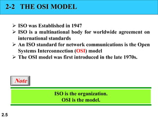
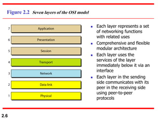
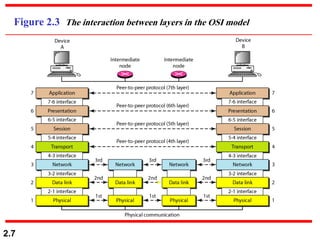
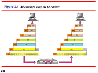
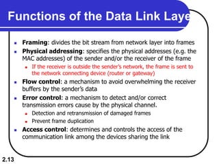
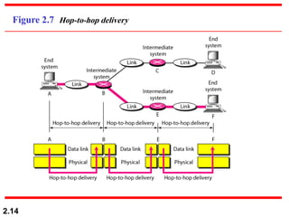
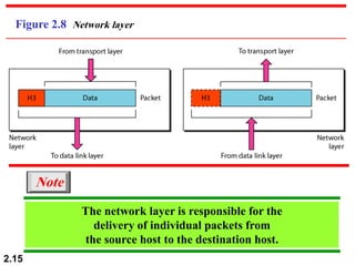
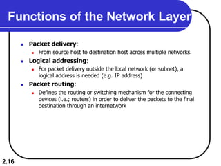
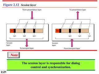
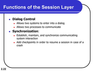
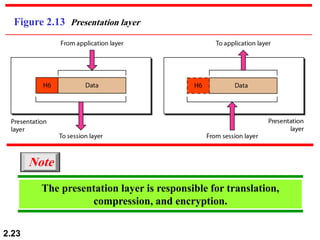
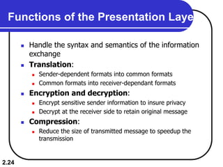
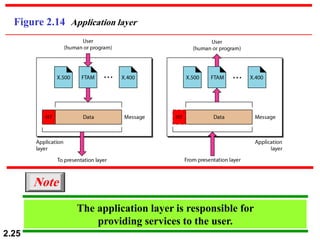
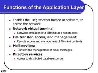
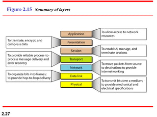
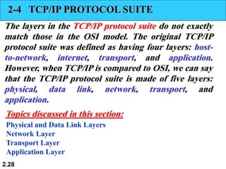
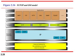
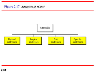
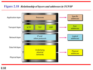
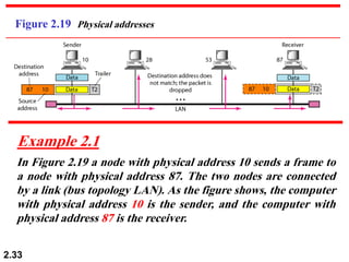
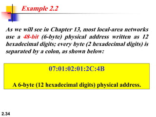
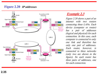
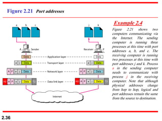
2.1
Chapter 2
Network Models
Copyright © The McGraw-Hill Companies, Inc. Permission required for reproduction or display.
2.2
2-1 LAYERED TASKS
We use the concept of layers in our daily life. As an
example, let us consider two friends who communicate
through postal mail. The process of sending a letter to a
friend would be complex if there were no services
available from the post office.
Sender, Receiver, and Carrier
Hierarchy
Topics discussed in this section:
2.3
2-1 LAYERED TASKS
 Example: Sending a letter
 Components:
 Sender, Receiver, and Carriers
 Hierarchy:
 The tasks are done in order
 Services: the relations between layers
 Each layer uses the services of the layer below it
2.4
Figure 2.1 Tasks involved in sending a letter
2.5
2-2 THE OSI MODEL
 ISO was Established in 1947
 ISO is a multinational body for worldwide agreement on
international standards
 An ISO standard for network communications is the Open
Systems Interconnection (OSI) model
 The OSI model was first introduced in the late 1970s.
ISO is the organization.
OSI is the model.
Note
2.6
Figure 2.2 Seven layers of the OSI model
 Each layer represents a set
of networking functions
with related uses
 Comprehensive and flexible
modular architecture
 Each layer uses the
services of the layer
immediately below it via an
interface
 Each layer in the sending
side communicates with its
peer in the receiving side
using peer-to-peer
protocols
2.7
Figure 2.3 The interaction between layers in the OSI model
2.8
Figure 2.4 An exchange using the OSI model
2.9
2-3 LAYERS IN THE OSI MODEL
In this section we briefly describe the functions of each
layer in the OSI model.
Physical Layer
Data Link Layer
Network Layer
Transport Layer
Session Layer
Presentation Layer
Application Layer
Topics discussed in this section:
2.10
Figure 2.5 Physical layer
The physical layer is responsible for movements of
individual bits from one hop (node) to the next.
Note
2.11
Functions of the Physical Layer
 The physical characteristics:
 The interface between devices and the transmission media
 Representation of bits:
 The type of encoding into signals
 Transmission data rate:
 The number of bits per second and the bit duration
 Synchronization of bit transmission:
 Clocks between the sender and receiver
 Line configuration:
 The connection of devices to the media
 Physical topology:
 mesh, star, bus, etc.
 Transmission mode:
 duplex, simplex, etc.
2.12
Figure 2.6 Data link layer
The data link layer is responsible for moving
frames from one hop (node) to the next.
Note
2.13
Functions of the Data Link Layer
 Framing: divides the bit stream from network layer into frames
 Physical addressing: specifies the physical addresses (e.g. the
MAC addresses) of the sender and/or the receiver of the frame
 If the receiver is outside the sender’s network, the frame is sent to
the network connecting device (router or gateway)
 Flow control: a mechanism to avoid overwhelming the receiver
buffers by the sender’s data
 Error control: a mechanism to detect and/or correct
transmission errors cause by the physical channel.
 Detection and retransmission of damaged frames
 Prevent frame duplication
 Access control: determines and controls the access of the
communication link among the devices sharing the link
2.14
Figure 2.7 Hop-to-hop delivery
2.15
Figure 2.8 Network layer
The network layer is responsible for the
delivery of individual packets from
the source host to the destination host.
Note
2.16
Functions of the Network Layer
 Packet delivery:
 From source host to destination host across multiple networks.
 Logical addressing:
 For packet delivery outside the local network (or subnet), a
logical address is needed (e.g. IP address)
 Packet routing:
 Defines the routing or switching mechanism for the connecting
devices (i.e.; routers) in order to deliver the packets to the final
destination through an internetwork
2.17
Figure 2.9 Source-to-destination delivery
2.18
Figure 2.10 Transport layer
The transport layer is responsible for the delivery
of a message from one process to another.
Note
2.19
Functions of the Transport Layer
 Message delivery:
 From a specific process in the sending host to a specific process in
the destination host
 Segmenting and reassembling:
 Divide the message from the application layer of the sender side
into transmittable segments containing sequence numbers
 Reassemble the segments into messages at the receiver side
 Connection control:
 The type of connection: connectionless or connection-oriented
 Connectionless: packet are sent independently (e.g. UDP protocol)
 Connection-oriented: a connection is first established with the peer
before delivering the packets (e.g. TCP protocol)
 End-to-end flow control
 End-to-end error control
2.20
Figure 2.11 Reliable process-to-process delivery of a message
2.21
Figure 2.12 Session layer
The session layer is responsible for dialog
control and synchronization.
Note
2.22
Functions of the Session Layer
 Dialog Control
 Allows two systems to enter into a dialog
 Allows two processes to communicate
 Synchronization:
 Establish, maintain, and synchronize communicating
system interaction
 Add checkpoints in order to resume a session in case of a
crash
2.23
Figure 2.13 Presentation layer
The presentation layer is responsible for translation,
compression, and encryption.
Note
2.24
Functions of the Presentation Layer
 Handle the syntax and semantics of the information
exchange
 Translation:
 Sender-dependent formats into common formats
 Common formats into receiver-dependant formats
 Encryption and decryption:
 Encrypt sensitive sender information to insure privacy
 Decrypt at the receiver side to retain original message
 Compression:
 Reduce the size of transmitted message to speedup the
transmission
2.25
Figure 2.14 Application layer
The application layer is responsible for
providing services to the user.
Note
2.26
Functions of the Application Layer
 Enables the user, whether human or software, to
access the network
 Network virtual terminal:
 Software emulation of a terminal at a remote host
 File transfer, access, and management:
 Remote access and management of files and contents
 Mail services:
 Transfer and management of email messages
 Directory services:
 Access to distributed database sources
2.27
Figure 2.15 Summary of layers
2.28
2-4 TCP/IP PROTOCOL SUITE
The layers in the TCP/IP protocol suite do not exactly
match those in the OSI model. The original TCP/IP
protocol suite was defined as having four layers: host-
to-network, internet, transport, and application.
However, when TCP/IP is compared to OSI, we can say
that the TCP/IP protocol suite is made of five layers:
physical, data link, network, transport, and
application.
Physical and Data Link Layers
Network Layer
Transport Layer
Application Layer
Topics discussed in this section:
2.29
Figure 2.16 TCP/IP and OSI model
2.30
2-5 ADDRESSING
Four levels of addresses are used in an internet
employing the TCP/IP protocols: physical, logical, port,
and specific.
Physical Addresses
Logical Addresses
Port Addresses
Specific Addresses
Topics discussed in this section:
2.31
Figure 2.17 Addresses in TCP/IP
2.32
Figure 2.18 Relationship of layers and addresses in TCP/IP
2.33
Figure 2.19 Physical addresses
In Figure 2.19 a node with physical address 10 sends a frame to
a node with physical address 87. The two nodes are connected
by a link (bus topology LAN). As the figure shows, the computer
with physical address 10 is the sender, and the computer with
physical address 87 is the receiver.
Example 2.1
2.34
As we will see in Chapter 13, most local-area networks
use a 48-bit (6-byte) physical address written as 12
hexadecimal digits; every byte (2 hexadecimal digits) is
separated by a colon, as shown below:
Example 2.2
07:01:02:01:2C:4B
A 6-byte (12 hexadecimal digits) physical address.
2.35
Figure 2.20 IP addresses
Figure 2.20 shows a part of an
internet with two routers
connecting three LANs. Each
device (computer or router)
has a pair of addresses
(logical and physical) for each
connection. In this case, each
computer is connected to only
one link and therefore has
only one pair of addresses.
Each router, however, is
connected to three networks
(only two are shown in the
figure). So each router has
three pairs of addresses, one
for each connection.
Example 2.3
2.36
Figure 2.21 Port addresses
Figure 2.21 shows two
computers communicating via
the Internet. The sending
computer is running three
processes at this time with port
addresses a, b, and c. The
receiving computer is running
two processes at this time with
port addresses j and k. Process
a in the sending computer
needs to communicate with
process j in the receiving
computer. Note that although
physical addresses change
from hop to hop, logical and
port addresses remain the same
from the source to destination.
Example 2.4
2.37
Example 2.5
As we will see in Chapter 23, a port address is a 16-bit
address represented by one decimal number as shown.
753
A 16-bit port address represented
as one single number.
The physical addresses change from hop to hop,
but the logical and port addresses usually remain the same.
Note

Computer Networks/Computer Engineering.pdf

  • 1.
    2.1 Chapter 2 Network Models Copyright© The McGraw-Hill Companies, Inc. Permission required for reproduction or display.
  • 2.
    2.2 2-1 LAYERED TASKS Weuse the concept of layers in our daily life. As an example, let us consider two friends who communicate through postal mail. The process of sending a letter to a friend would be complex if there were no services available from the post office. Sender, Receiver, and Carrier Hierarchy Topics discussed in this section:
  • 3.
    2.3 2-1 LAYERED TASKS Example: Sending a letter  Components:  Sender, Receiver, and Carriers  Hierarchy:  The tasks are done in order  Services: the relations between layers  Each layer uses the services of the layer below it
  • 4.
    2.4 Figure 2.1 Tasksinvolved in sending a letter
  • 5.
    2.5 2-2 THE OSIMODEL  ISO was Established in 1947  ISO is a multinational body for worldwide agreement on international standards  An ISO standard for network communications is the Open Systems Interconnection (OSI) model  The OSI model was first introduced in the late 1970s. ISO is the organization. OSI is the model. Note
  • 6.
    2.6 Figure 2.2 Sevenlayers of the OSI model  Each layer represents a set of networking functions with related uses  Comprehensive and flexible modular architecture  Each layer uses the services of the layer immediately below it via an interface  Each layer in the sending side communicates with its peer in the receiving side using peer-to-peer protocols
  • 7.
    2.7 Figure 2.3 Theinteraction between layers in the OSI model
  • 8.
    2.8 Figure 2.4 Anexchange using the OSI model
  • 9.
    2.9 2-3 LAYERS INTHE OSI MODEL In this section we briefly describe the functions of each layer in the OSI model. Physical Layer Data Link Layer Network Layer Transport Layer Session Layer Presentation Layer Application Layer Topics discussed in this section:
  • 10.
    2.10 Figure 2.5 Physicallayer The physical layer is responsible for movements of individual bits from one hop (node) to the next. Note
  • 11.
    2.11 Functions of thePhysical Layer  The physical characteristics:  The interface between devices and the transmission media  Representation of bits:  The type of encoding into signals  Transmission data rate:  The number of bits per second and the bit duration  Synchronization of bit transmission:  Clocks between the sender and receiver  Line configuration:  The connection of devices to the media  Physical topology:  mesh, star, bus, etc.  Transmission mode:  duplex, simplex, etc.
  • 12.
    2.12 Figure 2.6 Datalink layer The data link layer is responsible for moving frames from one hop (node) to the next. Note
  • 13.
    2.13 Functions of theData Link Layer  Framing: divides the bit stream from network layer into frames  Physical addressing: specifies the physical addresses (e.g. the MAC addresses) of the sender and/or the receiver of the frame  If the receiver is outside the sender’s network, the frame is sent to the network connecting device (router or gateway)  Flow control: a mechanism to avoid overwhelming the receiver buffers by the sender’s data  Error control: a mechanism to detect and/or correct transmission errors cause by the physical channel.  Detection and retransmission of damaged frames  Prevent frame duplication  Access control: determines and controls the access of the communication link among the devices sharing the link
  • 14.
  • 15.
    2.15 Figure 2.8 Networklayer The network layer is responsible for the delivery of individual packets from the source host to the destination host. Note
  • 16.
    2.16 Functions of theNetwork Layer  Packet delivery:  From source host to destination host across multiple networks.  Logical addressing:  For packet delivery outside the local network (or subnet), a logical address is needed (e.g. IP address)  Packet routing:  Defines the routing or switching mechanism for the connecting devices (i.e.; routers) in order to deliver the packets to the final destination through an internetwork
  • 17.
  • 18.
    2.18 Figure 2.10 Transportlayer The transport layer is responsible for the delivery of a message from one process to another. Note
  • 19.
    2.19 Functions of theTransport Layer  Message delivery:  From a specific process in the sending host to a specific process in the destination host  Segmenting and reassembling:  Divide the message from the application layer of the sender side into transmittable segments containing sequence numbers  Reassemble the segments into messages at the receiver side  Connection control:  The type of connection: connectionless or connection-oriented  Connectionless: packet are sent independently (e.g. UDP protocol)  Connection-oriented: a connection is first established with the peer before delivering the packets (e.g. TCP protocol)  End-to-end flow control  End-to-end error control
  • 20.
    2.20 Figure 2.11 Reliableprocess-to-process delivery of a message
  • 21.
    2.21 Figure 2.12 Sessionlayer The session layer is responsible for dialog control and synchronization. Note
  • 22.
    2.22 Functions of theSession Layer  Dialog Control  Allows two systems to enter into a dialog  Allows two processes to communicate  Synchronization:  Establish, maintain, and synchronize communicating system interaction  Add checkpoints in order to resume a session in case of a crash
  • 23.
    2.23 Figure 2.13 Presentationlayer The presentation layer is responsible for translation, compression, and encryption. Note
  • 24.
    2.24 Functions of thePresentation Layer  Handle the syntax and semantics of the information exchange  Translation:  Sender-dependent formats into common formats  Common formats into receiver-dependant formats  Encryption and decryption:  Encrypt sensitive sender information to insure privacy  Decrypt at the receiver side to retain original message  Compression:  Reduce the size of transmitted message to speedup the transmission
  • 25.
    2.25 Figure 2.14 Applicationlayer The application layer is responsible for providing services to the user. Note
  • 26.
    2.26 Functions of theApplication Layer  Enables the user, whether human or software, to access the network  Network virtual terminal:  Software emulation of a terminal at a remote host  File transfer, access, and management:  Remote access and management of files and contents  Mail services:  Transfer and management of email messages  Directory services:  Access to distributed database sources
  • 27.
  • 28.
    2.28 2-4 TCP/IP PROTOCOLSUITE The layers in the TCP/IP protocol suite do not exactly match those in the OSI model. The original TCP/IP protocol suite was defined as having four layers: host- to-network, internet, transport, and application. However, when TCP/IP is compared to OSI, we can say that the TCP/IP protocol suite is made of five layers: physical, data link, network, transport, and application. Physical and Data Link Layers Network Layer Transport Layer Application Layer Topics discussed in this section:
  • 29.
  • 30.
    2.30 2-5 ADDRESSING Four levelsof addresses are used in an internet employing the TCP/IP protocols: physical, logical, port, and specific. Physical Addresses Logical Addresses Port Addresses Specific Addresses Topics discussed in this section:
  • 31.
  • 32.
    2.32 Figure 2.18 Relationshipof layers and addresses in TCP/IP
  • 33.
    2.33 Figure 2.19 Physicaladdresses In Figure 2.19 a node with physical address 10 sends a frame to a node with physical address 87. The two nodes are connected by a link (bus topology LAN). As the figure shows, the computer with physical address 10 is the sender, and the computer with physical address 87 is the receiver. Example 2.1
  • 34.
    2.34 As we willsee in Chapter 13, most local-area networks use a 48-bit (6-byte) physical address written as 12 hexadecimal digits; every byte (2 hexadecimal digits) is separated by a colon, as shown below: Example 2.2 07:01:02:01:2C:4B A 6-byte (12 hexadecimal digits) physical address.
  • 35.
    2.35 Figure 2.20 IPaddresses Figure 2.20 shows a part of an internet with two routers connecting three LANs. Each device (computer or router) has a pair of addresses (logical and physical) for each connection. In this case, each computer is connected to only one link and therefore has only one pair of addresses. Each router, however, is connected to three networks (only two are shown in the figure). So each router has three pairs of addresses, one for each connection. Example 2.3
  • 36.
    2.36 Figure 2.21 Portaddresses Figure 2.21 shows two computers communicating via the Internet. The sending computer is running three processes at this time with port addresses a, b, and c. The receiving computer is running two processes at this time with port addresses j and k. Process a in the sending computer needs to communicate with process j in the receiving computer. Note that although physical addresses change from hop to hop, logical and port addresses remain the same from the source to destination. Example 2.4
  • 37.
    2.37 Example 2.5 As wewill see in Chapter 23, a port address is a 16-bit address represented by one decimal number as shown. 753 A 16-bit port address represented as one single number. The physical addresses change from hop to hop, but the logical and port addresses usually remain the same. Note