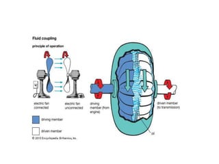
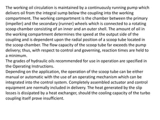
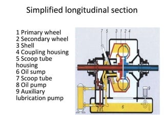
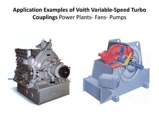
There is no mechanical interconnection between the
impeller and the rotor (i.e. the driving and driven units)
and the power is transmitted by virtue of the fluid filled in
the coupling. The impeller when rotated by the prime
mover imparts velocity and energy to the fluid, which is
converted into mechanical energy in the rotor thus
rotating it. The fluid follows a closed circuit of flow from
impeller to rotor through the air gap at the outer
periphery and from rotor to impeller again through the air
gap at the inner periphery. To enable the fluid to flow
from impeller to rotor it is essential that there is
difference in the "head" between the two and thus it is
essential that there is difference in R.P.M., known as slip
between the two. Slip is an important and inherent
characteristic of a fluid coupling resulting in several
desired advantages. As the slip increases more and more
fluid can be transferred from the impeller to the rotor and
more torque is transmitted. However when the rotor is at
standstill, maximum fluid is transmitted from the coupling.
The maximum torque is limiting torque. The fluid coupling
also acts as a torque limiter.
Fluid Coupling
Industrial Fluid Coupling
A fluid coupling is a hydrodynamic
device used to transmit rotating
mechanical power. It has been used in
automobile transmission as an
alternative to a mechanical clutch. It
also has widespread application in
marine and industrial machine drives,
where variable speed operation and/or
controlled start-up without shock loading
of the power transmission system is
essential.
Scoop Control Variable Speed Couplings
These coupling have a sliding scoop tube which enters the
coupling rotating casing through central clearance. The oil
quantity level in the coupling can be varied which in operation
by changing the position of the scoop tube which determines
the oil level in the coupling. This change of oil level shifts the
torque characteristic of the coupling thus enabling step less
speed control .See the characteristic curve shown below.
The Voith variable speed turbo coupling is a
fluid coupling which transmits the energy input
by the mass forces of a fluid which is circulated
in a closed system between an impeller on the
driving (primary) shaft and a runner of similar
design on the driven (secondary) shaft.
The section drawing shows the typical form of
the coupling blade arrangement and the layout
of the impellers in the working area.
In contrast to the constant-fill type turbo
coupling, the oil filling of the variable-speed
turbo coupling can be varied between
completely filled and drained while in
operation. In this way, infinitely variable speed
control of the driven machine is achieved over a
large range when the coupling operates against
the load characteristics. This control range is
dependent upon the load characteristic (torque
relative to speed) and the required governing
accuracy.
Voith Variable-Speed Turbo coupling
1 Primary wheel
2 Secondary wheel
3 Shell
4 Coupling housing
5 Scoop tube housing
6 Oil sump
7 Scoop tube
8 Oil pump
9 Auxiliary lubrication pump
The working oil circulation is maintained by a continuously running pump which
delivers oil from the integral sump below the coupling into the working
compartment. The working compartment is the chamber between the primary
(impeller) and the secondary (runner) wheels which is connected to a rotating
scoop chamber consisting of an inner and an outer shell. The amount of oil in
the working compartment determines the speed at the output side of the
coupling and is dependent upon the radial position of a scoop tube located in
the scoop chamber. The flow capacity of the scoop tube far exceeds the pump
delivery; thus, with respect to control and governing, reaction times are held to
a minimum.
The grades of hydraulic oils recommended for use in operation are specified in
the Operating Instructions.
Depending on the application, the operation of the scoop tube can be either
manual or automatic with the use of an operating mechanism which can be
integrated into the control system. Completely assembled actuator and control
equipment are normally included in delivery. The heat generated by the slip
losses is dissipated by a heat exchanger, should the cooling capacity of the turbo
coupling itself prove insufficient.
Simplified longitudinal section
1 Primary wheel
2 Secondary wheel
3 Shell
4 Coupling housing
5 Scoop tube
housing
6 Oil sump
7 Scoop tube
8 Oil pump
9 Auxiliary
lubrication pump
Application Examples of Voith Variable-Speed Turbo
Couplings Power Plants- Fans- Pumps

Variable speed hydraulic drive

  • 1.
    There is nomechanical interconnection between the impeller and the rotor (i.e. the driving and driven units) and the power is transmitted by virtue of the fluid filled in the coupling. The impeller when rotated by the prime mover imparts velocity and energy to the fluid, which is converted into mechanical energy in the rotor thus rotating it. The fluid follows a closed circuit of flow from impeller to rotor through the air gap at the outer periphery and from rotor to impeller again through the air gap at the inner periphery. To enable the fluid to flow from impeller to rotor it is essential that there is difference in the "head" between the two and thus it is essential that there is difference in R.P.M., known as slip between the two. Slip is an important and inherent characteristic of a fluid coupling resulting in several desired advantages. As the slip increases more and more fluid can be transferred from the impeller to the rotor and more torque is transmitted. However when the rotor is at standstill, maximum fluid is transmitted from the coupling. The maximum torque is limiting torque. The fluid coupling also acts as a torque limiter. Fluid Coupling
  • 3.
    Industrial Fluid Coupling Afluid coupling is a hydrodynamic device used to transmit rotating mechanical power. It has been used in automobile transmission as an alternative to a mechanical clutch. It also has widespread application in marine and industrial machine drives, where variable speed operation and/or controlled start-up without shock loading of the power transmission system is essential.
  • 4.
    Scoop Control VariableSpeed Couplings These coupling have a sliding scoop tube which enters the coupling rotating casing through central clearance. The oil quantity level in the coupling can be varied which in operation by changing the position of the scoop tube which determines the oil level in the coupling. This change of oil level shifts the torque characteristic of the coupling thus enabling step less speed control .See the characteristic curve shown below.
  • 5.
    The Voith variablespeed turbo coupling is a fluid coupling which transmits the energy input by the mass forces of a fluid which is circulated in a closed system between an impeller on the driving (primary) shaft and a runner of similar design on the driven (secondary) shaft. The section drawing shows the typical form of the coupling blade arrangement and the layout of the impellers in the working area. In contrast to the constant-fill type turbo coupling, the oil filling of the variable-speed turbo coupling can be varied between completely filled and drained while in operation. In this way, infinitely variable speed control of the driven machine is achieved over a large range when the coupling operates against the load characteristics. This control range is dependent upon the load characteristic (torque relative to speed) and the required governing accuracy. Voith Variable-Speed Turbo coupling 1 Primary wheel 2 Secondary wheel 3 Shell 4 Coupling housing 5 Scoop tube housing 6 Oil sump 7 Scoop tube 8 Oil pump 9 Auxiliary lubrication pump
  • 6.
    The working oilcirculation is maintained by a continuously running pump which delivers oil from the integral sump below the coupling into the working compartment. The working compartment is the chamber between the primary (impeller) and the secondary (runner) wheels which is connected to a rotating scoop chamber consisting of an inner and an outer shell. The amount of oil in the working compartment determines the speed at the output side of the coupling and is dependent upon the radial position of a scoop tube located in the scoop chamber. The flow capacity of the scoop tube far exceeds the pump delivery; thus, with respect to control and governing, reaction times are held to a minimum. The grades of hydraulic oils recommended for use in operation are specified in the Operating Instructions. Depending on the application, the operation of the scoop tube can be either manual or automatic with the use of an operating mechanism which can be integrated into the control system. Completely assembled actuator and control equipment are normally included in delivery. The heat generated by the slip losses is dissipated by a heat exchanger, should the cooling capacity of the turbo coupling itself prove insufficient.
  • 7.
    Simplified longitudinal section 1Primary wheel 2 Secondary wheel 3 Shell 4 Coupling housing 5 Scoop tube housing 6 Oil sump 7 Scoop tube 8 Oil pump 9 Auxiliary lubrication pump
  • 8.
    Application Examples ofVoith Variable-Speed Turbo Couplings Power Plants- Fans- Pumps