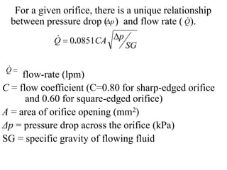
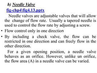
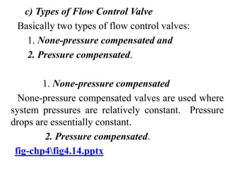
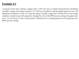
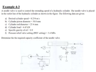
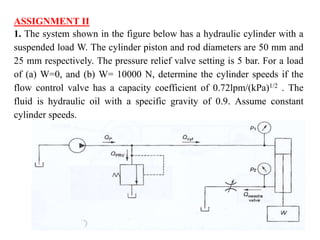
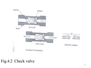
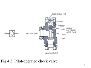
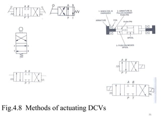
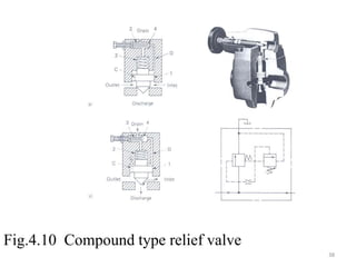
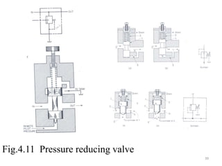
SlideShare a Scribd company logo
1 of 42
CHAPTER 4
VALVES
2
4.1. Introduction
Contents
4.2. Types of Valves
4.2.1 Directional Control Valves
4.2.2 Pressure Control Valves
4.2.3 Flow Control Valves
3
4.1 Introduction
• Control is the most important consideration in any
system.
• If control system components are not properly
selected, the entire system will not function as
required.
• Valves are used in fluid power system to control
direction, pressure and flow. Also the selection of
valves involves the type, size, actuating techniques
etc of the system.
4
4.2 Types of Valves
There are three basic types of valves:
a) Directional control
b) Pressure control
c) Flow control
4.2.1 Directional Control Valves (DCV)
• DCVs are used to control the direction of flow in a
hydraulic circuit. By determining the path, the
direction change in cylinder or motor may be
accomplished.
• This control of the fluid path is accomplished by
check valves, shuttle valves, two-way, three-way,
four-way and five-way valves.
5
• The number of ports on the DCVs is identified
using the term “way”: flow path through valve or
“port” : a connection to a valve passage fig-
chp4fig4.1.pptx.
• Types of DCVs
 One-way valve: simple check valve; flow in one
direction only, has two ports. Pilot-operated check valve
(Valves may be direct acting or pilot operated from an
adjacent or remote location).
 Two-way valve: flow in both direction; simple shutoff
valves
 Three-way valve: three flow path
 Four-way valve : four flow path
 Five- way valve : five flow path
6
a) Check valves
• The simplest type of directional control valve.
• The purpose of check valve is to permit free flow in
one direction and prevent any flow in the opposite
direction.
• fig-chp4fig4.2.pptx provides two schematic
drawings ( one for the no-flow condition and one for
the free-flow condition) showing the internal
operation of poppet check valve. The figure also
shows the graphic symbol.
7
b) Pilot-operated check valve
• It is a second type of check valve. fig-
chp4fig4.3.pptx
• This type of check valve always permits flow in the
normally blocked opposite direction only if pilot
pressure is applied at the pilot pressure port of the
valve.
• In Fig. 4-3, the check valve poppet has the pilot
piston attached to the threaded poppet stem by a nut.
The light spring holds the poppet seated in a no-flow
condition by pushing against the pilot piston.
• Frequently used for locking hydraulic cylinder in
position.
8
c) Three-way valves
• A directional control valve whose primary function
is alternately to pressurize and exhaust on working
port
• Contains three ports, are typically of the spool
design rather than poppet design. fig-
chp4fig4.4.pptx
• A spool is a circular shaft containing lands (larger
diameter sections) that are machined to slide in a
very close fitting bore of the valve body. The
grooves between the lands provide the flow paths
between ports. Clearance between land and bore <
0.03mm.
9
• Used to operate cylinder or motor in one direction.
Single acting cylinders retracted by spring or other
means.
• Can be two position or three position
• Designation by No. of Ports/ No. of Positions ( for
example: a three-way valve that uses two positions
of the spool is called a three-way, two position
directional control valve.
• The spool can be positioned manually, mechanically,
by using pilot pressure or by using electrical
solenoid.
10
d)Four-way valves
• fig-chp4fig4.5.pptx shows a four-way valve design
and operation
• Has four ports (from functional point of view) and
four internal passages
• It can actuate a double acting cylinder
• Rotary or sliding
• 4/2 and 4/3 valves are common.
e) Five-way valve
• Used usually in pneumatic systems. fig-
chp4fig4.6.pptx
11
f) Shuttle valve
• It is another type of directional control valve. fig-
chp4fig4.7.pptx
• Shuttle valve provides a means for connecting two
lines to one output (it permits a system to operate
from either of the fluid power source).
• One application is for safety in the event that the
main pump can no longer provide a hydraulic power
to operate emergency devices.
12
Methods of actuating valves
• Manually actuated
• Mechanical actuated
• Pilot-actuated: applying air pressure against the
piston on either end of the spool
• Solenoid actuated
fig-chp4fig4.8.pptx
13
4.2.2 Pressure Control Valves
a) Simple pressure relief valve
• Most widely used type of pressure control valve.
• Relief valve limits system pressure and establishes
working pressure.
• Cracking pressure-Pressure which initially lifts the
valve.
fig-chp4fig4.9.pptx
• Directly operated and pilot operated.
14
b) Compound type relief valve
• Increase the pressure sensitivity by reducing the
pressure override.
• The inlet fluid goes through the back of the piston and
after moving the pilot poppet valve, it gets drained. This
effect reduces the pressure on the back of the piston
thus lifting the valve.
fig-chp4fig4.10.pptx
c) Pressure reducing valve:
fig-chp4fig4.11.pptx
• Limits the outlet pressure(normally open).
• Various operating ranges and also adjustable. When
pressure goes beyond the set value, the valve closes to
throttle the flow.
15
• Useful for operation of branch circuits (sequence
valve)
Sequence valves: Control the order of operation
of two parallel branch circuits.
• Common examples of application include the
operation of two work cylinders in sequence such
that the second one activates after the complete
extension of the first (stalling increases the pressure
which raises the valve to allow flow to the other
cylinder).
16
c) Counterbalance valves:
• Used to maintain back pressure to prevent a load
from falling. Common applications include vertical
presses, loaders, lift trucks, etc. fig-
chp4fig4.12.pptx
• The valve is to open at a pressure above the pressure
required to prevent the vertical cylinder from
descending due to the weight of its load. The
pressure is applied at the blank end.
• If operated directly, pressure on the rod end of the
ram must exceed the pressure setting of the valve.
Usually 10% greater than the pressure required to
sustain the vertical load.
17
4.1.3 Flow Control (FCV)
• Primary function: controlling rate of flow,
velocity control of cylinders, speed control of
hydraulic motors. fig-chp4fig4.13.pptx
• Accurate speed control of pneumatic cylinders is
difficult to achieve because of compressibility effect
Orifice as a Flow Meter or Flow Control Device
An orifice ( a disk with a hole through which
fluid flows) installed in a pipe. Such a device can be
used as a flow meter by measuring a pressure drop
across the orifice. It is also used to control the flow
rate. The area of the orifice is fixed.
18
4.1.3 Flow Control (FCV)
• Primary function: controlling rate of flow,
velocity control of cylinders, speed control of
hydraulic motors.
• Accurate speed control of pneumatic cylinders is
difficult to achieve because of compressibility effect
a) Orifice as a Flow Meter or Flow Control Device
Orifice is used to determine flow rate by
measurement of pressure drop between inlet and
exit. It is also used to control the flow rate. The
area of the orifice is fixed.
For a given orifice, there is a unique relationship
between pressure drop ( ) and flow rate ( ).
flow-rate (lpm)
C = flow coefficient (C=0.80 for sharp-edged orifice
and 0.60 for square-edged orifice)
A = area of orifice opening (mm2)
Δp = pressure drop across the orifice (kPa)
SG = specific gravity of flowing fluid

Q

SG
p
CA
Q 
 0851
0.

p
 Q

b) Needle Valve
fig-chp4fig4.13.pptx
Needle valves are adjustable valves that will allow
the change of flow rate. Usually a tapered needle is
used to control the flow rate by adjusting a screw.
• Flow control only in one direction
• By including a check valve, the flow can be
restricted in one direction and can freely flow in the
other direction.
For a given opening position, a needle valve
behaves as an orifice. However, unlike un orifice,
the flow area (A) in a needle valve can be varied.
Control is achieved by varying the flow area.
Q = volume flow rate (l/m)
Cv = capacity coefficient (lpm/√kPa)
Δp = pressure drop across the valve (kPa)
SG = specific gravity
SG
p
C
Q v



c) Types of Flow Control Valve
Basically two types of flow control valves:
1. None-pressure compensated and
2. Pressure compensated.
1. None-pressure compensated
None-pressure compensated valves are used where
system pressures are relatively constant. Pressure
drops are essentially constant.
2. Pressure compensated.
fig-chp4fig4.14.pptx
23
• Temperature compensation: increase in
temperature reduces viscosity (hydraulics) which in
turn increases flow rate.
Compensation needed by a temperature sensitive
element to increase flow. Or use a knife sharp edge
orifice to eliminate temperature rise. Flow variations
<5% experienced within temperature range of 68o-
140oF using sharp-edged orifices.
Example 4-1
Example 4-2
Example 4-3
ASSIGNMENT II
1. The system shown in the figure below has a hydraulic cylinder with a
suspended load W. The cylinder piston and rod diameters are 50 mm and
25 mm respectively. The pressure relief valve setting is 5 bar. For a load
of (a) W=0, and (b) W= 10000 N, determine the cylinder speeds if the
flow control valve has a capacity coefficient of 0.72lpm/(kPa)1/2 . The
fluid is hydraulic oil with a specific gravity of 0.9. Assume constant
cylinder speeds.
2. A 55-mm diameter sharp-edged orifice is placed in a
pipeline to measure flow rate. If the measured pressure
drop is 300kPa and the fluid specific gravity is 0.9, find the
flow rate in m3/s.
3. A pressure relief valve contains a poppet with a 4.20 cm2
area on which system pressure acts. During assembly a
spring with spring constant of 3200 N/cm is installed in the
valve to hold the poppet against its seat. In order to pass
full pump flow through the valve at the PRV pressure
setting, the poppet must move 0.3 cm from its fully closed
position. What should be the initial compression of the
spring in the PRV if the full pump flow pressure is to be
40% greater than the cracking pressure?
Fig.4.1 DCVs position
29
Fig.4.2 Check valve
30
Fig.4.3 Pilot-operated check valve
31
Fig.4.4 Three-way valve
32
Fig.4.5 Four-way valve
33
Fig.4.6 Five-way valve
34
Fig.4.7 Shuttle valve
35
Fig.4.8 Methods of actuating DCVs
36
Fig.4.9 Pressure relief valve
37
Fig.4.10 Compound type relief valve
38
Fig.4.11 Pressure reducing valve
39
Fig.4.12 Counter balance valve
40
Fig.4.13 Flow control valve (FCV)
41
Fig.4.14 Operation of pressure-compensated flow control
valve
42

More Related Content

Similar to chapter four_ fluid power system lect.pptx

Control valve characteristics.pptx
Control valve characteristics.pptxControl valve characteristics.pptx
Control valve characteristics.pptxChitra Boobalan
 
Hydraulic control system (ce ppt)
Hydraulic control system (ce ppt)Hydraulic control system (ce ppt)
Hydraulic control system (ce ppt)Deep Chaudhari
 
Hydraulic control system (ce ppt)
Hydraulic control system (ce ppt)Hydraulic control system (ce ppt)
Hydraulic control system (ce ppt)Deep Chaudhari
 
Module 3 hydraulic control valves
Module 3 hydraulic control valvesModule 3 hydraulic control valves
Module 3 hydraulic control valvessrinivaspp
 
Week 3 1_hydraulics_valve3
Week 3 1_hydraulics_valve3Week 3 1_hydraulics_valve3
Week 3 1_hydraulics_valve3akmal ariffin
 
Hydraulic Circuit Contents..pptx
Hydraulic Circuit Contents..pptxHydraulic Circuit Contents..pptx
Hydraulic Circuit Contents..pptxAhmdSbhy
 
Hydraulics & pneumatics (AU) Unit-II
Hydraulics & pneumatics (AU)   Unit-IIHydraulics & pneumatics (AU)   Unit-II
Hydraulics & pneumatics (AU) Unit-IIArul Prakasam G
 
Fundamental of hydraulic components
Fundamental of hydraulic componentsFundamental of hydraulic components
Fundamental of hydraulic componentsPrasadroshan Mythin
 
Chapter six hydraulic circuit design and analysis.pptx
Chapter six  hydraulic circuit design and analysis.pptxChapter six  hydraulic circuit design and analysis.pptx
Chapter six hydraulic circuit design and analysis.pptxnurcam1
 
Ce.pptx 2
Ce.pptx 2Ce.pptx 2
Ce.pptx 2Hrdbs
 
HYDRAULICS & PNEUMATICS UNIT-4
HYDRAULICS & PNEUMATICS UNIT-4HYDRAULICS & PNEUMATICS UNIT-4
HYDRAULICS & PNEUMATICS UNIT-4Karthik R
 
Chapter_three fluid Lecture note on pumps.pptx
Chapter_three fluid Lecture note on pumps.pptxChapter_three fluid Lecture note on pumps.pptx
Chapter_three fluid Lecture note on pumps.pptxnurcam1
 
Hydraulics and Pneumatics.pdf
Hydraulics and Pneumatics.pdfHydraulics and Pneumatics.pdf
Hydraulics and Pneumatics.pdfPulungDwiAnggoro1
 
Hydrolics and Pneumatics overall Pdf.pdf
Hydrolics and Pneumatics overall Pdf.pdfHydrolics and Pneumatics overall Pdf.pdf
Hydrolics and Pneumatics overall Pdf.pdfMcLuretFernando
 

Similar to chapter four_ fluid power system lect.pptx (20)

Control valve characteristics.pptx
Control valve characteristics.pptxControl valve characteristics.pptx
Control valve characteristics.pptx
 
Hydraulic control system (ce ppt)
Hydraulic control system (ce ppt)Hydraulic control system (ce ppt)
Hydraulic control system (ce ppt)
 
Hydraulic control system (ce ppt)
Hydraulic control system (ce ppt)Hydraulic control system (ce ppt)
Hydraulic control system (ce ppt)
 
Module 3 hydraulic control valves
Module 3 hydraulic control valvesModule 3 hydraulic control valves
Module 3 hydraulic control valves
 
Shuttle valve
Shuttle valveShuttle valve
Shuttle valve
 
DOC-20240201-WA0004..pdf
DOC-20240201-WA0004..pdfDOC-20240201-WA0004..pdf
DOC-20240201-WA0004..pdf
 
Week 3 1_hydraulics_valve3
Week 3 1_hydraulics_valve3Week 3 1_hydraulics_valve3
Week 3 1_hydraulics_valve3
 
Hydraulic Circuit Contents..pptx
Hydraulic Circuit Contents..pptxHydraulic Circuit Contents..pptx
Hydraulic Circuit Contents..pptx
 
Hydraulics & pneumatics (AU) Unit-II
Hydraulics & pneumatics (AU)   Unit-IIHydraulics & pneumatics (AU)   Unit-II
Hydraulics & pneumatics (AU) Unit-II
 
Fundamental of hydraulic components
Fundamental of hydraulic componentsFundamental of hydraulic components
Fundamental of hydraulic components
 
Hydraulic course manual
Hydraulic course manualHydraulic course manual
Hydraulic course manual
 
Dc valve
Dc  valve Dc  valve
Dc valve
 
Chapter six hydraulic circuit design and analysis.pptx
Chapter six  hydraulic circuit design and analysis.pptxChapter six  hydraulic circuit design and analysis.pptx
Chapter six hydraulic circuit design and analysis.pptx
 
Ce.pptx 2
Ce.pptx 2Ce.pptx 2
Ce.pptx 2
 
HP UNIT 4 PPT
HP UNIT 4 PPT HP UNIT 4 PPT
HP UNIT 4 PPT
 
HYDRAULICS & PNEUMATICS UNIT-4
HYDRAULICS & PNEUMATICS UNIT-4HYDRAULICS & PNEUMATICS UNIT-4
HYDRAULICS & PNEUMATICS UNIT-4
 
Unit 4
Unit 4Unit 4
Unit 4
 
Chapter_three fluid Lecture note on pumps.pptx
Chapter_three fluid Lecture note on pumps.pptxChapter_three fluid Lecture note on pumps.pptx
Chapter_three fluid Lecture note on pumps.pptx
 
Hydraulics and Pneumatics.pdf
Hydraulics and Pneumatics.pdfHydraulics and Pneumatics.pdf
Hydraulics and Pneumatics.pdf
 
Hydrolics and Pneumatics overall Pdf.pdf
Hydrolics and Pneumatics overall Pdf.pdfHydrolics and Pneumatics overall Pdf.pdf
Hydrolics and Pneumatics overall Pdf.pdf
 

Recently uploaded

Glass Ceramics: Processing and Properties
Glass Ceramics: Processing and PropertiesGlass Ceramics: Processing and Properties
Glass Ceramics: Processing and PropertiesPrabhanshu Chaturvedi
 
Double rodded leveling 1 pdf activity 01
Double rodded leveling 1 pdf activity 01Double rodded leveling 1 pdf activity 01
Double rodded leveling 1 pdf activity 01KreezheaRecto
 
UNIT-II FMM-Flow Through Circular Conduits
UNIT-II FMM-Flow Through Circular ConduitsUNIT-II FMM-Flow Through Circular Conduits
UNIT-II FMM-Flow Through Circular Conduitsrknatarajan
 
ONLINE FOOD ORDER SYSTEM PROJECT REPORT.pdf
ONLINE FOOD ORDER SYSTEM PROJECT REPORT.pdfONLINE FOOD ORDER SYSTEM PROJECT REPORT.pdf
ONLINE FOOD ORDER SYSTEM PROJECT REPORT.pdfKamal Acharya
 
Unit 1 - Soil Classification and Compaction.pdf
Unit 1 - Soil Classification and Compaction.pdfUnit 1 - Soil Classification and Compaction.pdf
Unit 1 - Soil Classification and Compaction.pdfRagavanV2
 
Call for Papers - Educational Administration: Theory and Practice, E-ISSN: 21...
Call for Papers - Educational Administration: Theory and Practice, E-ISSN: 21...Call for Papers - Educational Administration: Theory and Practice, E-ISSN: 21...
Call for Papers - Educational Administration: Theory and Practice, E-ISSN: 21...Christo Ananth
 
Intze Overhead Water Tank Design by Working Stress - IS Method.pdf
Intze Overhead Water Tank  Design by Working Stress - IS Method.pdfIntze Overhead Water Tank  Design by Working Stress - IS Method.pdf
Intze Overhead Water Tank Design by Working Stress - IS Method.pdfSuman Jyoti
 
UNIT-IFLUID PROPERTIES & FLOW CHARACTERISTICS
UNIT-IFLUID PROPERTIES & FLOW CHARACTERISTICSUNIT-IFLUID PROPERTIES & FLOW CHARACTERISTICS
UNIT-IFLUID PROPERTIES & FLOW CHARACTERISTICSrknatarajan
 
Call for Papers - International Journal of Intelligent Systems and Applicatio...
Call for Papers - International Journal of Intelligent Systems and Applicatio...Call for Papers - International Journal of Intelligent Systems and Applicatio...
Call for Papers - International Journal of Intelligent Systems and Applicatio...Christo Ananth
 
VIP Call Girls Ankleshwar 7001035870 Whatsapp Number, 24/07 Booking
VIP Call Girls Ankleshwar 7001035870 Whatsapp Number, 24/07 BookingVIP Call Girls Ankleshwar 7001035870 Whatsapp Number, 24/07 Booking
VIP Call Girls Ankleshwar 7001035870 Whatsapp Number, 24/07 Bookingdharasingh5698
 
Structural Analysis and Design of Foundations: A Comprehensive Handbook for S...
Structural Analysis and Design of Foundations: A Comprehensive Handbook for S...Structural Analysis and Design of Foundations: A Comprehensive Handbook for S...
Structural Analysis and Design of Foundations: A Comprehensive Handbook for S...Dr.Costas Sachpazis
 
Call Girls Walvekar Nagar Call Me 7737669865 Budget Friendly No Advance Booking
Call Girls Walvekar Nagar Call Me 7737669865 Budget Friendly No Advance BookingCall Girls Walvekar Nagar Call Me 7737669865 Budget Friendly No Advance Booking
Call Girls Walvekar Nagar Call Me 7737669865 Budget Friendly No Advance Bookingroncy bisnoi
 
result management system report for college project
result management system report for college projectresult management system report for college project
result management system report for college projectTonystark477637
 
VIP Model Call Girls Kothrud ( Pune ) Call ON 8005736733 Starting From 5K to ...
VIP Model Call Girls Kothrud ( Pune ) Call ON 8005736733 Starting From 5K to ...VIP Model Call Girls Kothrud ( Pune ) Call ON 8005736733 Starting From 5K to ...
VIP Model Call Girls Kothrud ( Pune ) Call ON 8005736733 Starting From 5K to ...SUHANI PANDEY
 
UNIT - IV - Air Compressors and its Performance
UNIT - IV - Air Compressors and its PerformanceUNIT - IV - Air Compressors and its Performance
UNIT - IV - Air Compressors and its Performancesivaprakash250
 
chapter 5.pptx: drainage and irrigation engineering
chapter 5.pptx: drainage and irrigation engineeringchapter 5.pptx: drainage and irrigation engineering
chapter 5.pptx: drainage and irrigation engineeringmulugeta48
 

Recently uploaded (20)

Glass Ceramics: Processing and Properties
Glass Ceramics: Processing and PropertiesGlass Ceramics: Processing and Properties
Glass Ceramics: Processing and Properties
 
Double rodded leveling 1 pdf activity 01
Double rodded leveling 1 pdf activity 01Double rodded leveling 1 pdf activity 01
Double rodded leveling 1 pdf activity 01
 
UNIT-II FMM-Flow Through Circular Conduits
UNIT-II FMM-Flow Through Circular ConduitsUNIT-II FMM-Flow Through Circular Conduits
UNIT-II FMM-Flow Through Circular Conduits
 
ONLINE FOOD ORDER SYSTEM PROJECT REPORT.pdf
ONLINE FOOD ORDER SYSTEM PROJECT REPORT.pdfONLINE FOOD ORDER SYSTEM PROJECT REPORT.pdf
ONLINE FOOD ORDER SYSTEM PROJECT REPORT.pdf
 
(INDIRA) Call Girl Aurangabad Call Now 8617697112 Aurangabad Escorts 24x7
(INDIRA) Call Girl Aurangabad Call Now 8617697112 Aurangabad Escorts 24x7(INDIRA) Call Girl Aurangabad Call Now 8617697112 Aurangabad Escorts 24x7
(INDIRA) Call Girl Aurangabad Call Now 8617697112 Aurangabad Escorts 24x7
 
Unit 1 - Soil Classification and Compaction.pdf
Unit 1 - Soil Classification and Compaction.pdfUnit 1 - Soil Classification and Compaction.pdf
Unit 1 - Soil Classification and Compaction.pdf
 
Call for Papers - Educational Administration: Theory and Practice, E-ISSN: 21...
Call for Papers - Educational Administration: Theory and Practice, E-ISSN: 21...Call for Papers - Educational Administration: Theory and Practice, E-ISSN: 21...
Call for Papers - Educational Administration: Theory and Practice, E-ISSN: 21...
 
(INDIRA) Call Girl Bhosari Call Now 8617697112 Bhosari Escorts 24x7
(INDIRA) Call Girl Bhosari Call Now 8617697112 Bhosari Escorts 24x7(INDIRA) Call Girl Bhosari Call Now 8617697112 Bhosari Escorts 24x7
(INDIRA) Call Girl Bhosari Call Now 8617697112 Bhosari Escorts 24x7
 
Intze Overhead Water Tank Design by Working Stress - IS Method.pdf
Intze Overhead Water Tank  Design by Working Stress - IS Method.pdfIntze Overhead Water Tank  Design by Working Stress - IS Method.pdf
Intze Overhead Water Tank Design by Working Stress - IS Method.pdf
 
UNIT-IFLUID PROPERTIES & FLOW CHARACTERISTICS
UNIT-IFLUID PROPERTIES & FLOW CHARACTERISTICSUNIT-IFLUID PROPERTIES & FLOW CHARACTERISTICS
UNIT-IFLUID PROPERTIES & FLOW CHARACTERISTICS
 
Call for Papers - International Journal of Intelligent Systems and Applicatio...
Call for Papers - International Journal of Intelligent Systems and Applicatio...Call for Papers - International Journal of Intelligent Systems and Applicatio...
Call for Papers - International Journal of Intelligent Systems and Applicatio...
 
VIP Call Girls Ankleshwar 7001035870 Whatsapp Number, 24/07 Booking
VIP Call Girls Ankleshwar 7001035870 Whatsapp Number, 24/07 BookingVIP Call Girls Ankleshwar 7001035870 Whatsapp Number, 24/07 Booking
VIP Call Girls Ankleshwar 7001035870 Whatsapp Number, 24/07 Booking
 
Structural Analysis and Design of Foundations: A Comprehensive Handbook for S...
Structural Analysis and Design of Foundations: A Comprehensive Handbook for S...Structural Analysis and Design of Foundations: A Comprehensive Handbook for S...
Structural Analysis and Design of Foundations: A Comprehensive Handbook for S...
 
Call Girls Walvekar Nagar Call Me 7737669865 Budget Friendly No Advance Booking
Call Girls Walvekar Nagar Call Me 7737669865 Budget Friendly No Advance BookingCall Girls Walvekar Nagar Call Me 7737669865 Budget Friendly No Advance Booking
Call Girls Walvekar Nagar Call Me 7737669865 Budget Friendly No Advance Booking
 
result management system report for college project
result management system report for college projectresult management system report for college project
result management system report for college project
 
VIP Model Call Girls Kothrud ( Pune ) Call ON 8005736733 Starting From 5K to ...
VIP Model Call Girls Kothrud ( Pune ) Call ON 8005736733 Starting From 5K to ...VIP Model Call Girls Kothrud ( Pune ) Call ON 8005736733 Starting From 5K to ...
VIP Model Call Girls Kothrud ( Pune ) Call ON 8005736733 Starting From 5K to ...
 
UNIT - IV - Air Compressors and its Performance
UNIT - IV - Air Compressors and its PerformanceUNIT - IV - Air Compressors and its Performance
UNIT - IV - Air Compressors and its Performance
 
Call Now ≽ 9953056974 ≼🔝 Call Girls In New Ashok Nagar ≼🔝 Delhi door step de...
Call Now ≽ 9953056974 ≼🔝 Call Girls In New Ashok Nagar  ≼🔝 Delhi door step de...Call Now ≽ 9953056974 ≼🔝 Call Girls In New Ashok Nagar  ≼🔝 Delhi door step de...
Call Now ≽ 9953056974 ≼🔝 Call Girls In New Ashok Nagar ≼🔝 Delhi door step de...
 
Roadmap to Membership of RICS - Pathways and Routes
Roadmap to Membership of RICS - Pathways and RoutesRoadmap to Membership of RICS - Pathways and Routes
Roadmap to Membership of RICS - Pathways and Routes
 
chapter 5.pptx: drainage and irrigation engineering
chapter 5.pptx: drainage and irrigation engineeringchapter 5.pptx: drainage and irrigation engineering
chapter 5.pptx: drainage and irrigation engineering
 

chapter four_ fluid power system lect.pptx

  • 2. 2 4.1. Introduction Contents 4.2. Types of Valves 4.2.1 Directional Control Valves 4.2.2 Pressure Control Valves 4.2.3 Flow Control Valves
  • 3. 3 4.1 Introduction • Control is the most important consideration in any system. • If control system components are not properly selected, the entire system will not function as required. • Valves are used in fluid power system to control direction, pressure and flow. Also the selection of valves involves the type, size, actuating techniques etc of the system.
  • 4. 4 4.2 Types of Valves There are three basic types of valves: a) Directional control b) Pressure control c) Flow control 4.2.1 Directional Control Valves (DCV) • DCVs are used to control the direction of flow in a hydraulic circuit. By determining the path, the direction change in cylinder or motor may be accomplished. • This control of the fluid path is accomplished by check valves, shuttle valves, two-way, three-way, four-way and five-way valves.
  • 5. 5 • The number of ports on the DCVs is identified using the term “way”: flow path through valve or “port” : a connection to a valve passage fig- chp4fig4.1.pptx. • Types of DCVs  One-way valve: simple check valve; flow in one direction only, has two ports. Pilot-operated check valve (Valves may be direct acting or pilot operated from an adjacent or remote location).  Two-way valve: flow in both direction; simple shutoff valves  Three-way valve: three flow path  Four-way valve : four flow path  Five- way valve : five flow path
  • 6. 6 a) Check valves • The simplest type of directional control valve. • The purpose of check valve is to permit free flow in one direction and prevent any flow in the opposite direction. • fig-chp4fig4.2.pptx provides two schematic drawings ( one for the no-flow condition and one for the free-flow condition) showing the internal operation of poppet check valve. The figure also shows the graphic symbol.
  • 7. 7 b) Pilot-operated check valve • It is a second type of check valve. fig- chp4fig4.3.pptx • This type of check valve always permits flow in the normally blocked opposite direction only if pilot pressure is applied at the pilot pressure port of the valve. • In Fig. 4-3, the check valve poppet has the pilot piston attached to the threaded poppet stem by a nut. The light spring holds the poppet seated in a no-flow condition by pushing against the pilot piston. • Frequently used for locking hydraulic cylinder in position.
  • 8. 8 c) Three-way valves • A directional control valve whose primary function is alternately to pressurize and exhaust on working port • Contains three ports, are typically of the spool design rather than poppet design. fig- chp4fig4.4.pptx • A spool is a circular shaft containing lands (larger diameter sections) that are machined to slide in a very close fitting bore of the valve body. The grooves between the lands provide the flow paths between ports. Clearance between land and bore < 0.03mm.
  • 9. 9 • Used to operate cylinder or motor in one direction. Single acting cylinders retracted by spring or other means. • Can be two position or three position • Designation by No. of Ports/ No. of Positions ( for example: a three-way valve that uses two positions of the spool is called a three-way, two position directional control valve. • The spool can be positioned manually, mechanically, by using pilot pressure or by using electrical solenoid.
  • 10. 10 d)Four-way valves • fig-chp4fig4.5.pptx shows a four-way valve design and operation • Has four ports (from functional point of view) and four internal passages • It can actuate a double acting cylinder • Rotary or sliding • 4/2 and 4/3 valves are common. e) Five-way valve • Used usually in pneumatic systems. fig- chp4fig4.6.pptx
  • 11. 11 f) Shuttle valve • It is another type of directional control valve. fig- chp4fig4.7.pptx • Shuttle valve provides a means for connecting two lines to one output (it permits a system to operate from either of the fluid power source). • One application is for safety in the event that the main pump can no longer provide a hydraulic power to operate emergency devices.
  • 12. 12 Methods of actuating valves • Manually actuated • Mechanical actuated • Pilot-actuated: applying air pressure against the piston on either end of the spool • Solenoid actuated fig-chp4fig4.8.pptx
  • 13. 13 4.2.2 Pressure Control Valves a) Simple pressure relief valve • Most widely used type of pressure control valve. • Relief valve limits system pressure and establishes working pressure. • Cracking pressure-Pressure which initially lifts the valve. fig-chp4fig4.9.pptx • Directly operated and pilot operated.
  • 14. 14 b) Compound type relief valve • Increase the pressure sensitivity by reducing the pressure override. • The inlet fluid goes through the back of the piston and after moving the pilot poppet valve, it gets drained. This effect reduces the pressure on the back of the piston thus lifting the valve. fig-chp4fig4.10.pptx c) Pressure reducing valve: fig-chp4fig4.11.pptx • Limits the outlet pressure(normally open). • Various operating ranges and also adjustable. When pressure goes beyond the set value, the valve closes to throttle the flow.
  • 15. 15 • Useful for operation of branch circuits (sequence valve) Sequence valves: Control the order of operation of two parallel branch circuits. • Common examples of application include the operation of two work cylinders in sequence such that the second one activates after the complete extension of the first (stalling increases the pressure which raises the valve to allow flow to the other cylinder).
  • 16. 16 c) Counterbalance valves: • Used to maintain back pressure to prevent a load from falling. Common applications include vertical presses, loaders, lift trucks, etc. fig- chp4fig4.12.pptx • The valve is to open at a pressure above the pressure required to prevent the vertical cylinder from descending due to the weight of its load. The pressure is applied at the blank end. • If operated directly, pressure on the rod end of the ram must exceed the pressure setting of the valve. Usually 10% greater than the pressure required to sustain the vertical load.
  • 17. 17 4.1.3 Flow Control (FCV) • Primary function: controlling rate of flow, velocity control of cylinders, speed control of hydraulic motors. fig-chp4fig4.13.pptx • Accurate speed control of pneumatic cylinders is difficult to achieve because of compressibility effect Orifice as a Flow Meter or Flow Control Device An orifice ( a disk with a hole through which fluid flows) installed in a pipe. Such a device can be used as a flow meter by measuring a pressure drop across the orifice. It is also used to control the flow rate. The area of the orifice is fixed.
  • 18. 18 4.1.3 Flow Control (FCV) • Primary function: controlling rate of flow, velocity control of cylinders, speed control of hydraulic motors. • Accurate speed control of pneumatic cylinders is difficult to achieve because of compressibility effect a) Orifice as a Flow Meter or Flow Control Device Orifice is used to determine flow rate by measurement of pressure drop between inlet and exit. It is also used to control the flow rate. The area of the orifice is fixed.
  • 19. For a given orifice, there is a unique relationship between pressure drop ( ) and flow rate ( ). flow-rate (lpm) C = flow coefficient (C=0.80 for sharp-edged orifice and 0.60 for square-edged orifice) A = area of orifice opening (mm2) Δp = pressure drop across the orifice (kPa) SG = specific gravity of flowing fluid  Q  SG p CA Q   0851 0.  p  Q 
  • 20. b) Needle Valve fig-chp4fig4.13.pptx Needle valves are adjustable valves that will allow the change of flow rate. Usually a tapered needle is used to control the flow rate by adjusting a screw. • Flow control only in one direction • By including a check valve, the flow can be restricted in one direction and can freely flow in the other direction. For a given opening position, a needle valve behaves as an orifice. However, unlike un orifice, the flow area (A) in a needle valve can be varied.
  • 21. Control is achieved by varying the flow area. Q = volume flow rate (l/m) Cv = capacity coefficient (lpm/√kPa) Δp = pressure drop across the valve (kPa) SG = specific gravity SG p C Q v   
  • 22. c) Types of Flow Control Valve Basically two types of flow control valves: 1. None-pressure compensated and 2. Pressure compensated. 1. None-pressure compensated None-pressure compensated valves are used where system pressures are relatively constant. Pressure drops are essentially constant. 2. Pressure compensated. fig-chp4fig4.14.pptx
  • 23. 23 • Temperature compensation: increase in temperature reduces viscosity (hydraulics) which in turn increases flow rate. Compensation needed by a temperature sensitive element to increase flow. Or use a knife sharp edge orifice to eliminate temperature rise. Flow variations <5% experienced within temperature range of 68o- 140oF using sharp-edged orifices.
  • 27. ASSIGNMENT II 1. The system shown in the figure below has a hydraulic cylinder with a suspended load W. The cylinder piston and rod diameters are 50 mm and 25 mm respectively. The pressure relief valve setting is 5 bar. For a load of (a) W=0, and (b) W= 10000 N, determine the cylinder speeds if the flow control valve has a capacity coefficient of 0.72lpm/(kPa)1/2 . The fluid is hydraulic oil with a specific gravity of 0.9. Assume constant cylinder speeds.
  • 28. 2. A 55-mm diameter sharp-edged orifice is placed in a pipeline to measure flow rate. If the measured pressure drop is 300kPa and the fluid specific gravity is 0.9, find the flow rate in m3/s. 3. A pressure relief valve contains a poppet with a 4.20 cm2 area on which system pressure acts. During assembly a spring with spring constant of 3200 N/cm is installed in the valve to hold the poppet against its seat. In order to pass full pump flow through the valve at the PRV pressure setting, the poppet must move 0.3 cm from its fully closed position. What should be the initial compression of the spring in the PRV if the full pump flow pressure is to be 40% greater than the cracking pressure?
  • 36. Fig.4.8 Methods of actuating DCVs 36
  • 38. Fig.4.10 Compound type relief valve 38
  • 41. Fig.4.13 Flow control valve (FCV) 41
  • 42. Fig.4.14 Operation of pressure-compensated flow control valve 42