Download as PDF, PPTX

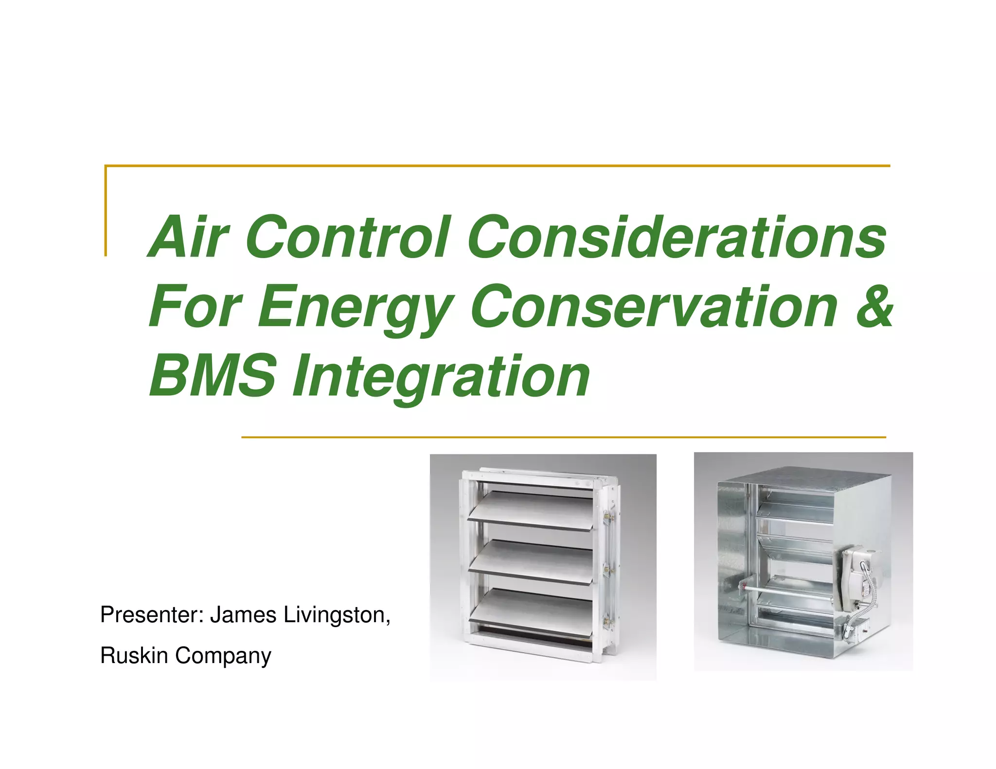
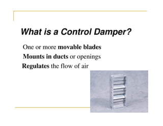
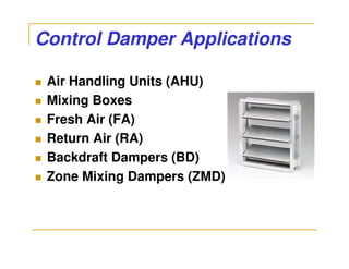
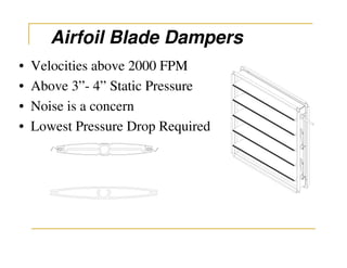
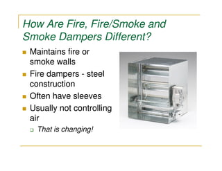
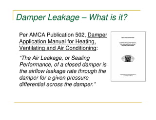
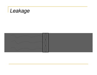
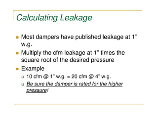

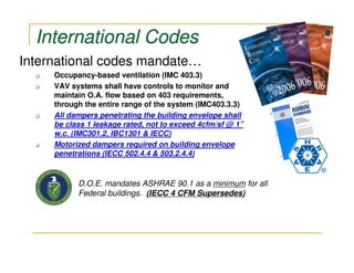
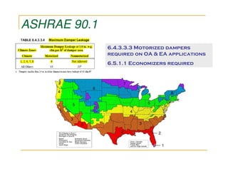
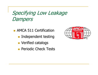
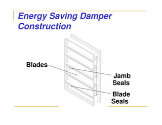
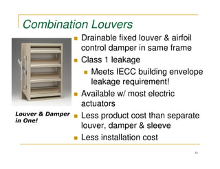
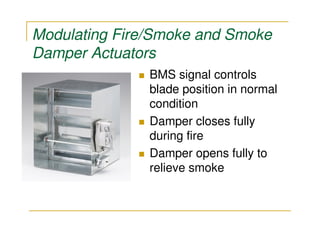
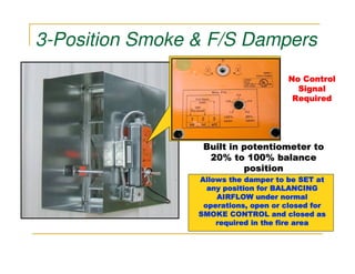
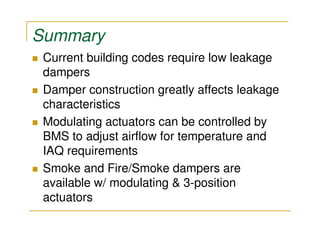

This document discusses control dampers and their integration into building management systems for energy conservation. It covers damper basics, leakage, design for energy efficiency, and fire/smoke damper actuators. Control dampers regulate air flow through ducts and openings. Properly specifying low leakage dampers and modulating actuators can improve energy efficiency. International building codes require low leakage dampers and economizers.