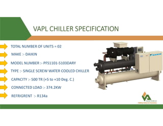
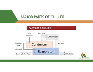
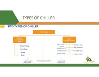
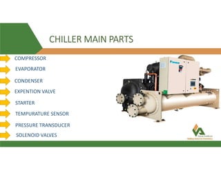
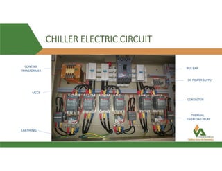
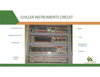
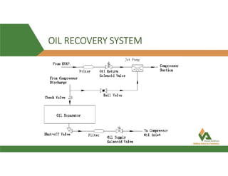
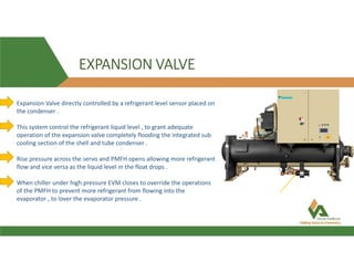
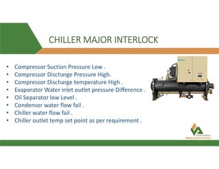
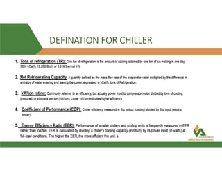
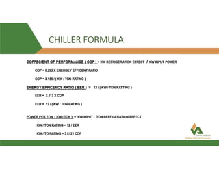
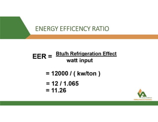
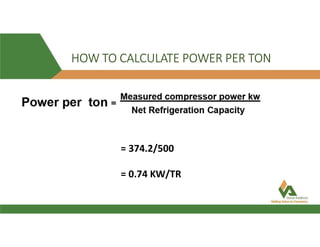
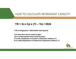
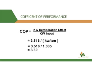
This document provides information about a 500 ton Daikin chiller unit with two compressors. It describes the major components of the chiller, including the compressor, evaporator, condenser, expansion valve and sensors. It explains the vapor compression refrigeration cycle and details the operation of the single screw compressor. It also outlines the chiller's electric and instrumentation circuits and lists some important chiller interlocks and definitions. Formulas are provided for calculating the unit's power per ton, refrigerant capacity, and coefficient of performance.


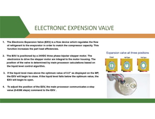


![Intern ppt ..kk [Autosaved].pptx](https://cdn.slidesharecdn.com/ss_thumbnails/internppt-231006135559-ff64c843-thumbnail.jpg?width=640&height=640&fit=bounds)