Downloaded 194 times
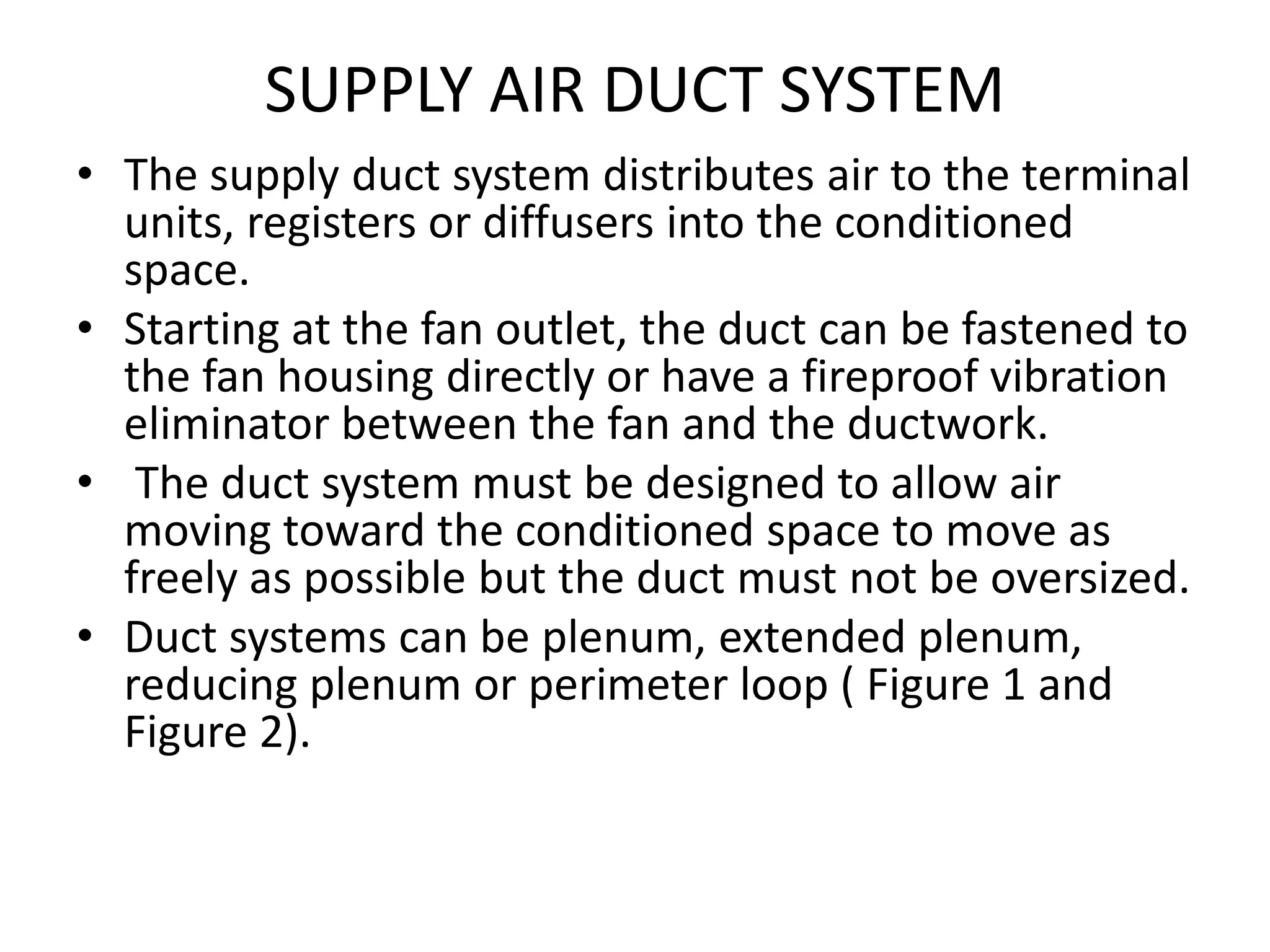
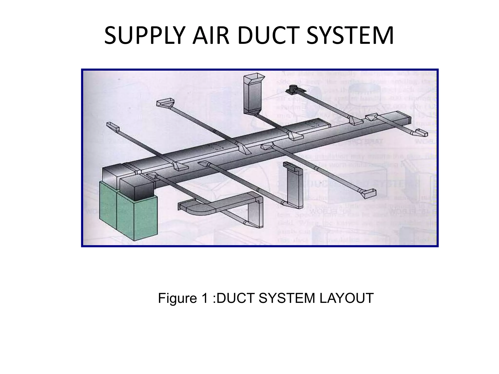
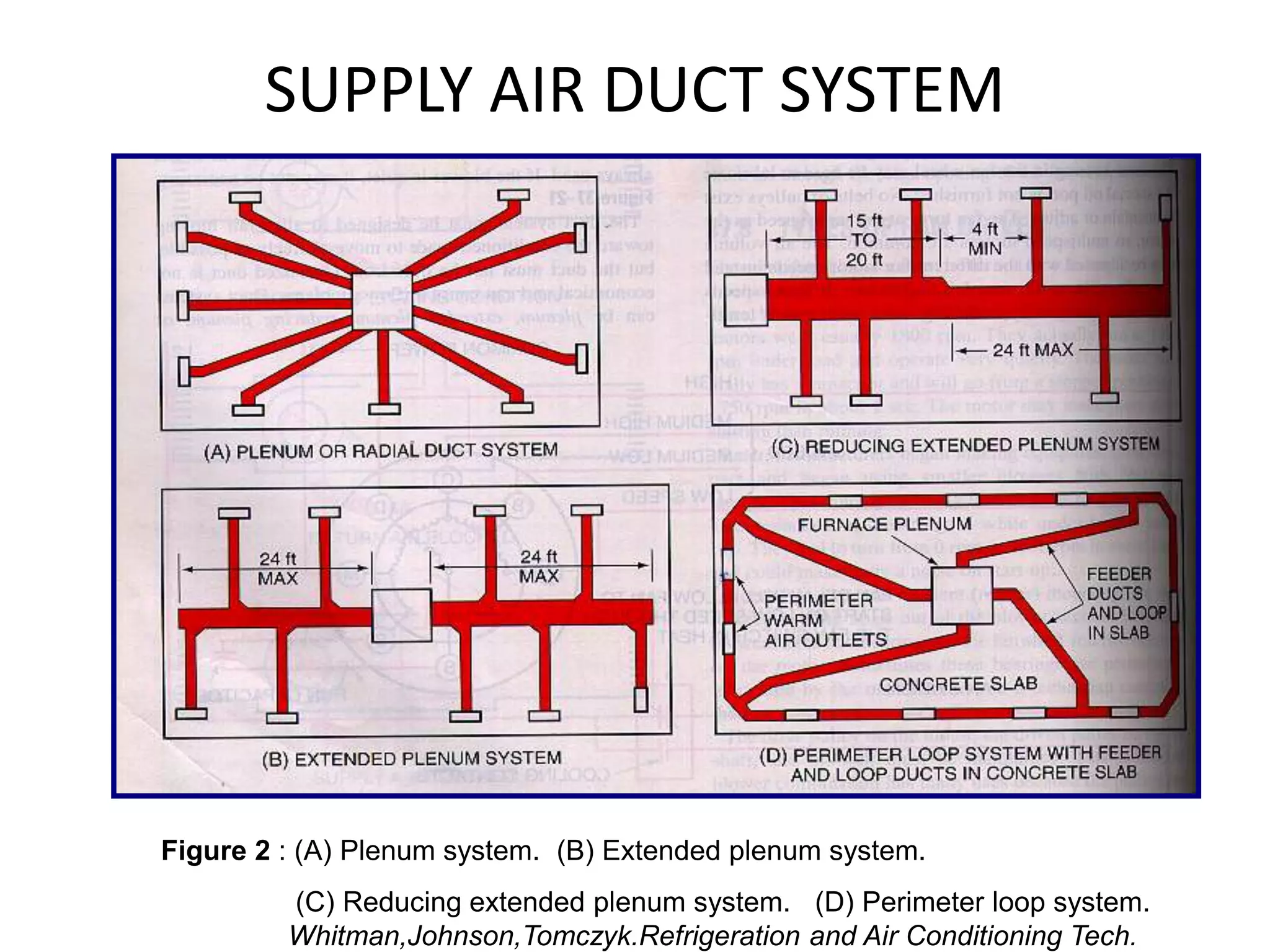
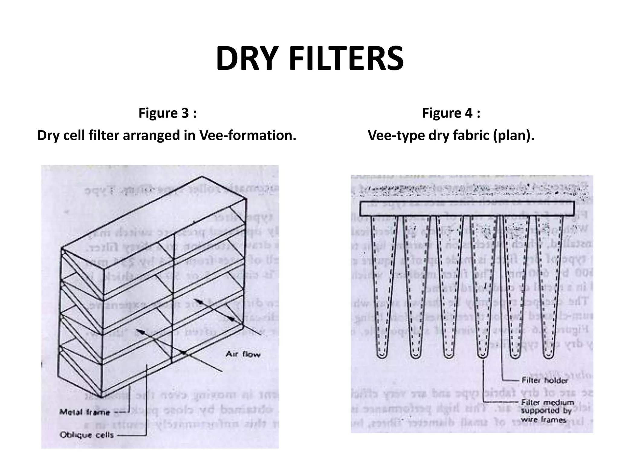


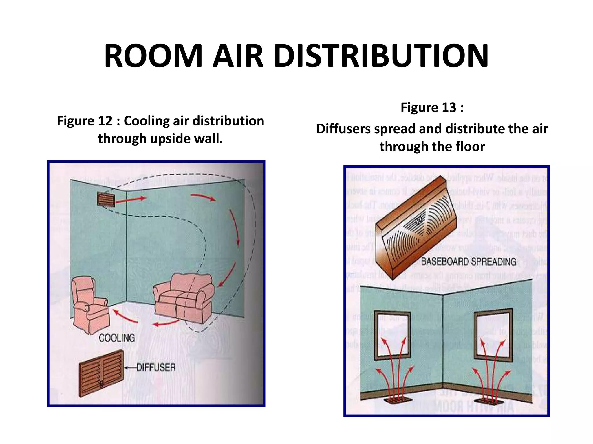
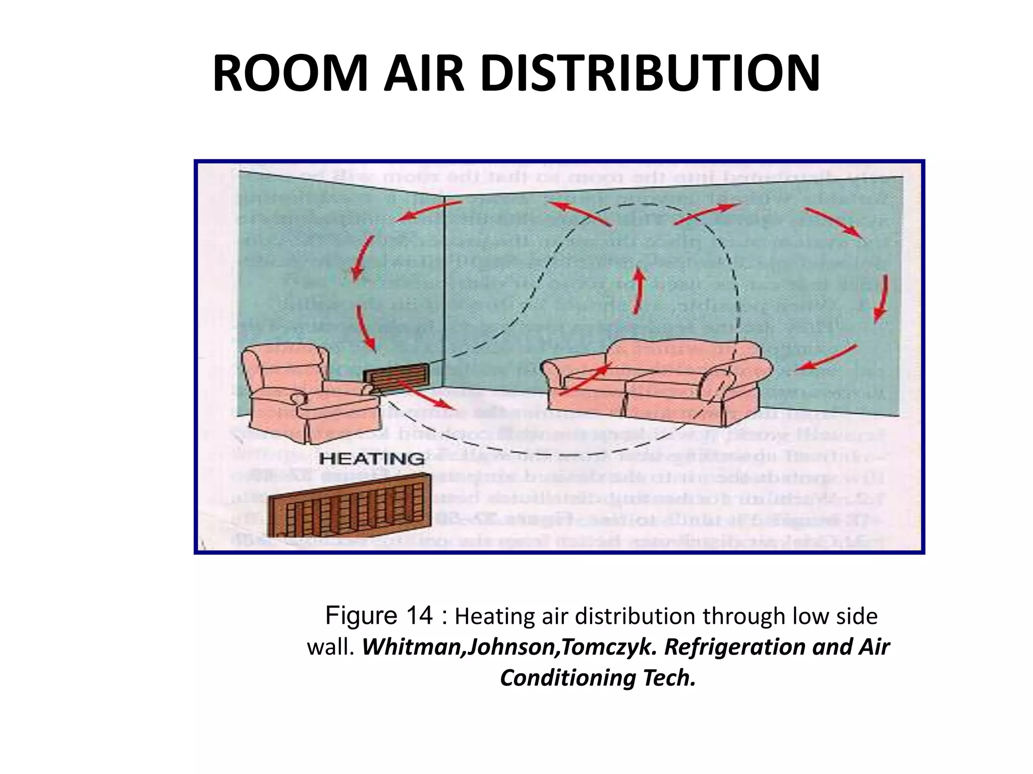


The document describes various components of an HVAC air distribution system, including supply ducts, return ducts, air filters, and room air distribution components. Supply duct systems can be plenum, extended plenum, reducing plenum, or perimeter loop systems. Common filter types are dry filters, viscous filters, and electrostatic filters. Balancing dampers are used to balance air flow. Air is distributed into rooms through grilles, registers, or diffusers located on walls or ceilings.