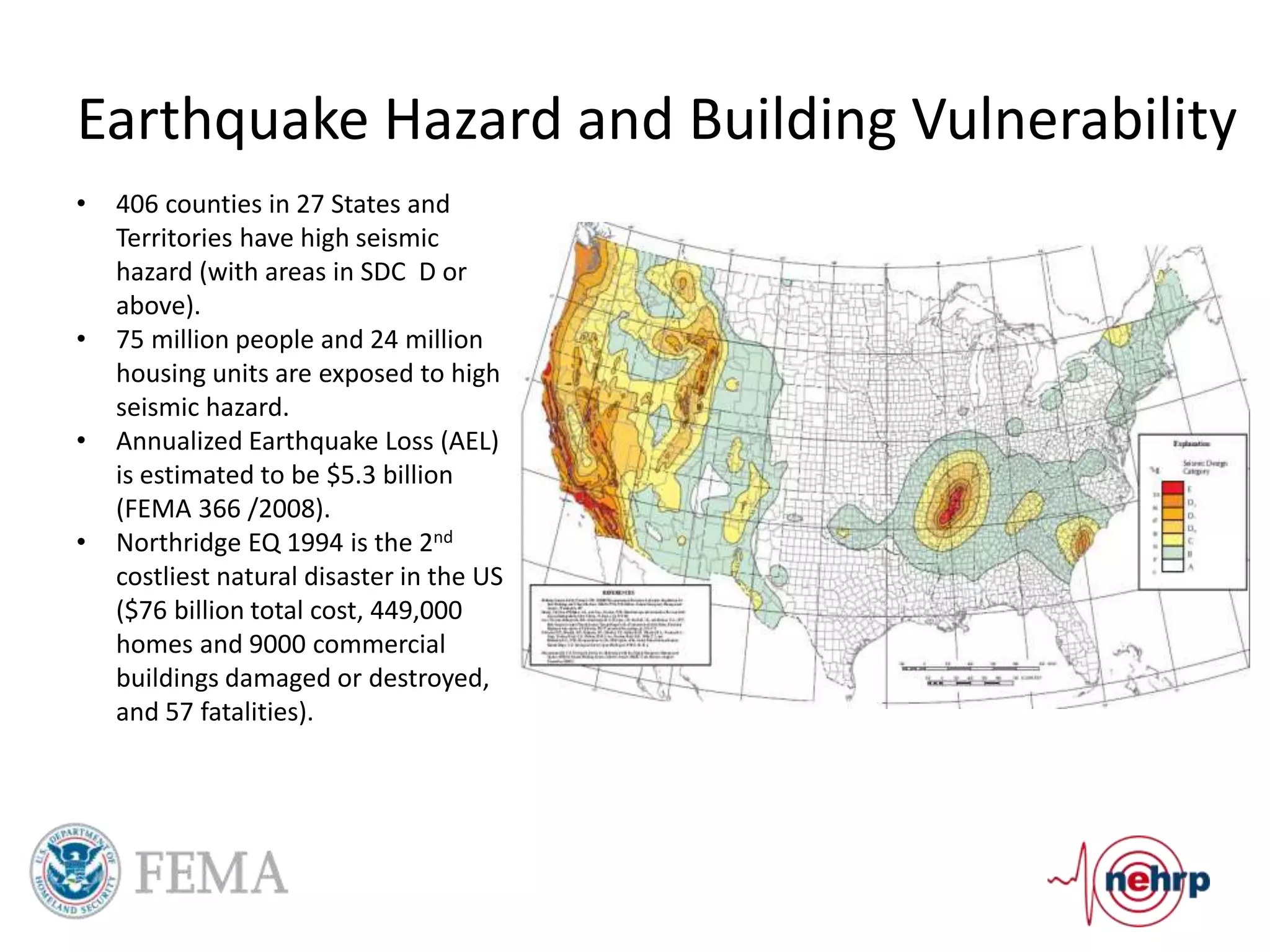
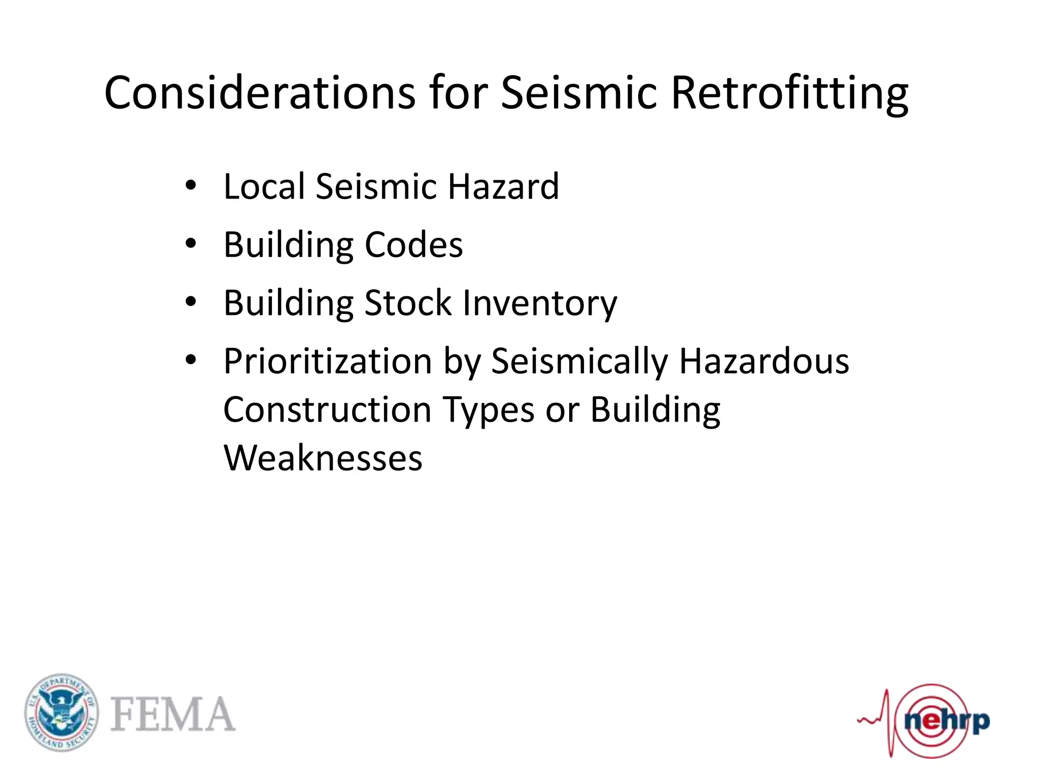
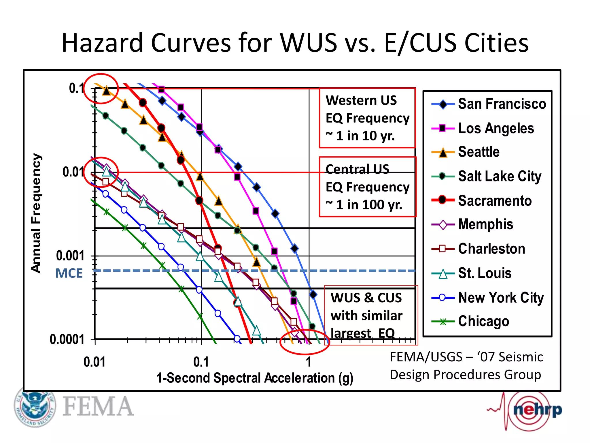
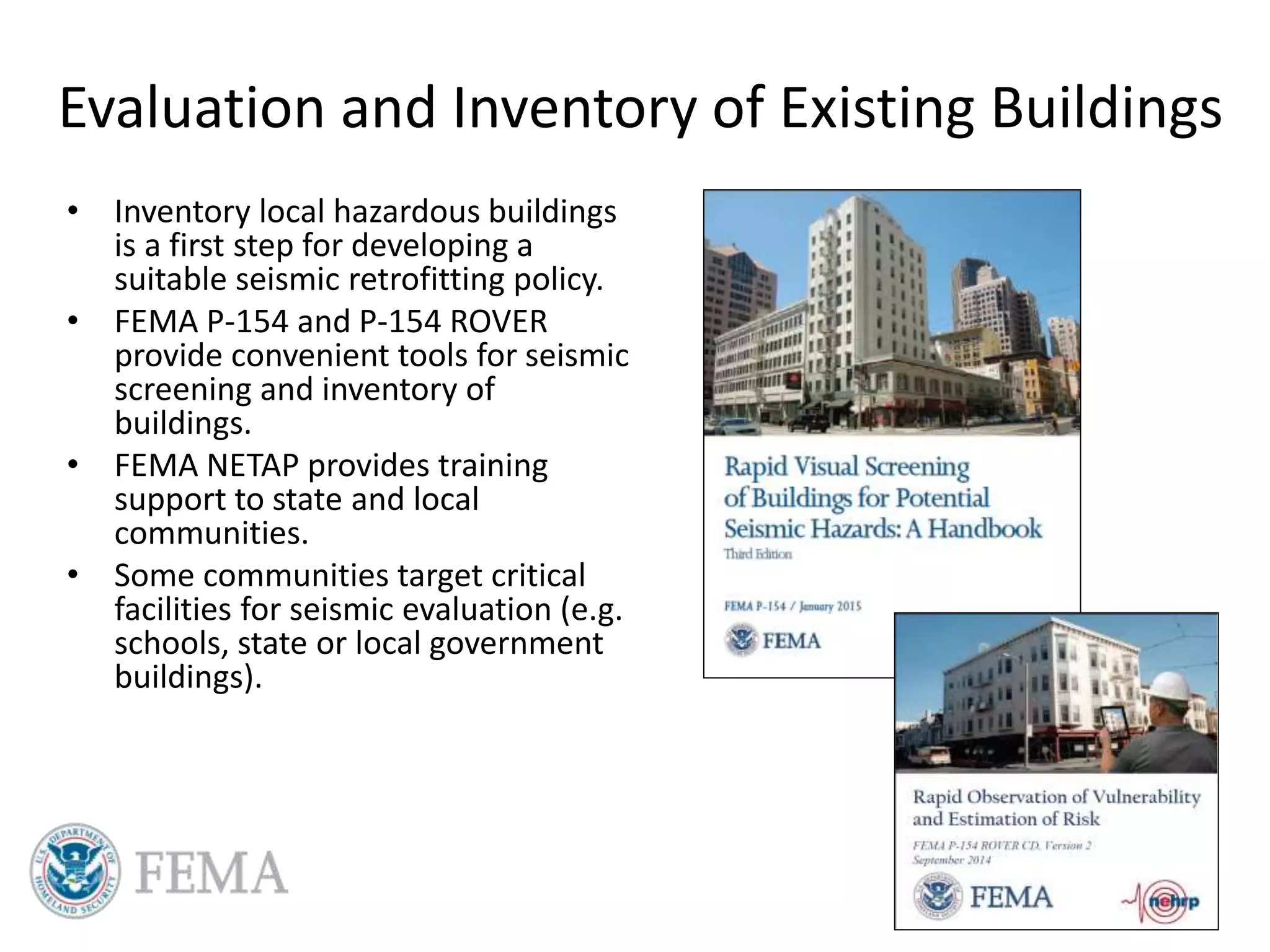
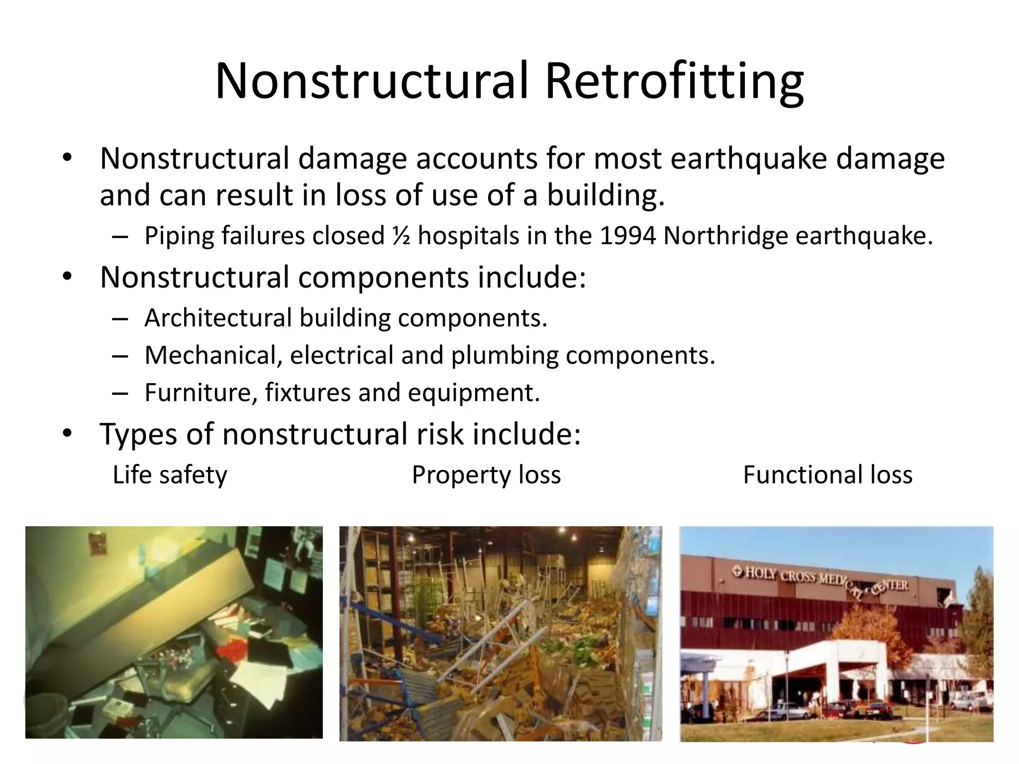
Presentation on considerations for seismic retrofitting. This presentation was given at the Natural Hazard Mitigation Association's annual Symposium held every July in Broomfield, Colorado.
This presentation was given by Mai (Mike) Tong of FEMA. Watch the whole presentation here: https://www.youtube.com/watch?v=alb6V8mbJEo
Pre-engineered steel buildings are designed and fabricated off-site using standardized structural components. They are lighter and more economical than conventional construction. The key components include tapered steel columns, rafters, purlins, girts, and sheet metal panels. Structural analysis and design are performed to calculate loads and optimize the frame based on factors like wind speed and seismic zone. Components are then erected on-site by connecting prefabricated pieces together using bolted joints.
This document summarizes a seminar presentation on shear walls. Shear walls are vertical structural elements that resist lateral forces like winds and earthquakes. They distribute forces from floors, roofs, and exterior walls to the foundation. The presentation covers the purpose, types, construction process, advantages of shear walls, including how they are more stable and ductile than conventional walls. Shear walls are typically used in tall buildings and provide lateral strength and stiffness to resist horizontal seismic forces.
This document is a project report on the design of a shear wall using STAAD Pro software. It includes an introduction to shear walls, which are vertical structural elements that resist lateral loads like wind and earthquakes. The report discusses the purpose, applications, advantages, and disadvantages of shear walls. It also describes the different types of shear walls and their behavior under loads. The design procedure for shear walls in STAAD Pro and as per reference codes is explained. The conclusion summarizes that shear walls provide strength and stiffness to resist lateral loads in buildings.
Pushover is a static-nonlinear analysis method where a structure is subjected to gravity loading and a monotonic displacement-controlled lateral load pattern which continuously increases through elastic and inelastic behavior until an ultimate condition is reached. Lateral load may represent the range of base shear induced by earthquake loading, and its configuration may be proportional to the distribution of mass along building height, mode shapes, or another practical means.
The static pushover analysis is becoming a popular tool for seismic performance evaluation of existing and new structures. The expectation is that the pushover analysis will provide adequate information on seismic demands imposed by the design ground motion on the structural system and its components. The purpose of the paper is to summarize the basic concepts on which the pushover analysis can be based, assess the accuracy of pushover predictions, identify conditions under which the pushover will provide adequate information and, perhaps more importantly, identify cases in which the pushover predictions will be inadequate or even misleading.
This document discusses the design of a multi-level car parking structure with 4 floors above ground (G+3). The building was designed using AutoCAD for planning and STAAD Pro for structural analysis. The design follows the limit state method and Indian code IS 456-2000. Structural elements like slabs, beams, columns, footings, and staircases were designed and detailed. The document discusses structural systems, loads, and methods of structural analysis used for multi-level buildings.
The document provides details of the computer aided design and analysis of a G+20 multi-storey residential building located in Patna using STAAD-Pro software. The building is designed as a reinforced concrete framed structure according to Indian codes IS 456, IS 875, and IS 1893. Load calculations are performed for dead loads, live loads, and wind loads. Analysis of the building is carried out to determine member forces from gravity and lateral loads.
The document discusses slip form construction, a method where concrete is poured into a continuously moving form. There are two main types - vertical forms that move upwards, and horizontal forms that move horizontally. Slip forming allows for continuous, jointless concrete structures and reduces construction time compared to traditional formwork. It requires careful planning of the construction process to achieve high productivity while ensuring safety.
This document discusses various techniques for retrofitting concrete structures to make them more resistant to seismic activity and other natural hazards. It defines retrofitting as modifying existing structures to increase resistance. Key techniques mentioned include adding new shear walls, steel bracing, column and beam jacketing with steel or concrete, base isolation using seismic isolators, mass reduction by removing floors, and wall thickening. The document also discusses challenges in retrofitting and standards from Indian codes for earthquake-resistant design. The conclusion emphasizes that retrofitting has matured but expertise is still lacking, and optimization is needed to determine the most cost-effective technique for a given structure.
The document discusses ductility and ductile detailing in reinforced concrete structures. It states that structures should be designed to have lateral strength, deformability, and ductility to resist earthquakes with limited damage and no collapse. Ductility allows structures to develop their full strength through internal force redistribution. Detailing of reinforcement is important to avoid brittle failure and induce ductile behavior by allowing steel to yield in a controlled manner. Shear walls are also discussed as vertical reinforced concrete elements that help structures resist earthquake loads in a ductile manner.
This document discusses various types of beam and column connections used in steel structures. It describes rigid, pinned, and semi-rigid connections. It also discusses different beam to beam connections like web cleat angle, clip and seat angle, and web and seat angle connections. Beam to column connections including web angle, clip and seat angle stiffened and unstiffened are explained. Finally, it covers moment resistant connections like eccentrically loaded, light moment and heavy moment connections and provides examples of designing some typical connections.
Shear walls are vertical reinforced concrete walls that resist lateral forces like wind and earthquakes. They provide strength and stiffness to control lateral building movement. Shear walls are classified into different types including simple rectangular, coupled, rigid frame, framed with infill, column supported, and core type walls. Design of shear walls involves reviewing the building layout, determining loads, estimating earthquake forces, analyzing the structural system, and designing for flexural and shear strengths with proper reinforcement detailing. The behavior of shear walls under seismic loading depends on their height to width ratio, with squat walls experiencing more shear deformation and slender walls undergoing primarily bending deformation.
Composite Concrete-Steel Construction in Tall Buildings by Dr. NaveedAIT Solutions
The document discusses composite concrete-steel construction systems used in tall buildings. It describes how composite and mixed systems use concrete and steel acting together to provide benefits like increased strength and stiffness. Common composite elements discussed include composite floors, beams, columns, shear walls, and link beams. Composite columns provide benefits like increased strength and stiffness. Concrete-filled steel tubes are an efficient composite column type. Recent developments in composite shear walls include concrete-filled composite plate shear wall systems that offer enhanced seismic performance. Case studies of composite tall buildings in Asia are also presented.
This document discusses static pushover analysis for seismic design performance assessment. It describes how to construct a pushover curve by defining a structural model and loads, and performing an analysis while controlling displacements. Two main methods are presented for using the pushover curve: the Capacity Spectrum Method (ATC-40) which constructs a capacity spectrum and determines a performance point, and the Displacement Coefficient Method (FEMA 273) which estimates a target displacement. The document also provides examples of modeling elements and their force-deformation properties for the pushover analysis.
This document provides an overview of the design process for reinforced concrete beams. It begins by outlining the basic steps, which include assuming section sizes and materials, calculating loads, checking moments, and sizing reinforcement. It then describes the types of beams as singly or doubly reinforced. Design considerations like the neutral axis and types of sections - balanced, under-reinforced, and over-reinforced - are explained. The detailed 10-step design procedure is then outlined, covering calculations for dimensions, reinforcement for bending and shear, serviceability checks, and providing design details.
This document discusses nonlinear static (pushover) analysis for assessing structural capacity against seismic actions. It provides an overview of key aspects of pushover analysis including:
1. Converting the response of a multi-degree of freedom system into an equivalent single-degree of freedom system for comparison to demand spectra.
2. Defining the capacity curve from the pushover analysis and establishing a bilinearized equivalent curve for demand evaluation.
3. Evaluating demand based on the equivalent linear system period and comparing displacements and ductility demands to the system capacity to determine safety.
This document discusses bolted connections used in structural engineering. It begins by explaining why connection failures should be avoided, as they can lead to catastrophic structural failures. It then classifies bolted connections based on their method of fastening, rigidity, joint resistance, fabrication location, joint location, connection geometry, and type of force transferred. It describes different types of bolts and bolt tightening techniques used for friction grip connections. It discusses advantages and drawbacks of bolted connections compared to riveted or welded connections. The document provides detailed information on design and behavior of various bolted connections.
Suspension bridges have several key components: cables that suspend the roadway from towers, towers that stabilize the cables, and anchorages that provide structure and keep the cables tight. A typical construction process involves building tower foundations, erecting the towers, installing saddles and cables between the towers, adding vertical suspender cables to hang the roadway, and constructing the deck between the towers. The main forces in a suspension bridge are tension in the cables and compression in the towers. Some of the world's largest suspension bridges include the Akashi Kaikyō Bridge in Japan and the Sidu River Bridge in China.
Columns are an important structural member that carry compressive loads and bending moments. They are composed of concrete reinforced with embedded steel. Columns make up 11% of a building's weight but must support 100% of the total weight. Reducing column size or number is not advisable. Column alignment and the moment of inertia 'I' value are also important, with a higher I providing more resistance to bending and deflection. Proper casting, curing, and avoiding honeycombing or voids are crucial for column strength.
Shear walls are preferred in seismic regions because they are very effective at resisting lateral forces during earthquakes. Shear walls are vertical structural elements designed to transfer seismic forces throughout the height of the building. They provide large strength, high stiffness, and ductility. Shear wall buildings have performed much better during past earthquakes compared to reinforced concrete frame buildings. Some key advantages of shear walls include good earthquake resistance when designed properly, easy construction, reduced construction costs, and minimized damage to structural and non-structural elements during seismic events.
This document provides guidelines for ductile detailing of reinforced concrete structures in seismic zones. It specifies that ductile detailing is required for structures in Seismic Zones IV and V, as well as some structures in Zone III. Concrete must have a minimum compressive strength of 20 MPa and steel reinforcement grade of Fe 415 or less. Flexural members must have a width-to-depth ratio over 0.3, width over 200mm, and depth less than 1/4 of clear span. Longitudinal reinforcement requires a minimum of two bars at top and bottom with minimum and maximum steel ratios specified. Joints and splices must be confined by hoops or laps exceeding development lengths to ensure ductility. Web reinforcement of closed
Structural analysis and design of multi storey pptSHIVUNAIKA B
This document summarizes the structural analysis and design of a multi-story residential building. The objectives were to gain experience designing such structures for economy, safety and durability. The process involved locating columns and beams, calculating loads, modeling the structure in STAAD.Pro, analyzing results, and designing various components including the foundation, columns, beams, and slabs according to the Indian code IS 456:2000. Load combinations, material properties, and reinforcement sizing were considered to satisfy strength and serviceability limit states.
This document discusses shear wall analysis and design. It defines shear walls as structural elements used in buildings to resist lateral forces through cantilever action. The document classifies different types of shear walls and discusses their behavior under seismic loading. It outlines the steps for designing shear walls, including reviewing layout, analyzing structural systems, determining design forces, and detailing reinforcement. The document emphasizes the importance of properly locating shear walls in a building to resist seismic loads and minimize torsional effects.
This document discusses shoring and underpinning methods used to provide temporary or permanent support to structures. Shoring provides temporary stability during construction or repairs using techniques like raking, flying, or dead shores made of timber or steel. Underpinning supports existing foundations by strengthening soils using pit, pile, or chemical methods to allow additions without disturbing the structure. Proper design, installation, and precautions are needed for both techniques.
Shear walls are vertical structural elements designed to resist lateral forces like winds and earthquakes. They work by transferring shear forces throughout their height and resisting uplift forces. Properly designed and constructed shear wall buildings are very stable and ductile, providing warnings before collapse during severe earthquakes. Common types of shear walls include reinforced concrete, plywood, and steel plate shear walls. Shear walls are an effective and efficient way to resist lateral loads in seismic regions.
The document provides steps for designing different structural elements:
1. Design of a beam subjected to torsion including calculation of torsional and bending moments, determination of steel requirements, and detailing.
2. Design of continuous beams involving calculation of bending moments and shears, reinforcement sizing, shear design, deflection check, and detailing including curtailment.
3. Design of circular water tanks with both flexible base and rigid base using approximate and IS code methods. This includes sizing hoop and vertical tension reinforcement, sizing wall thickness, designing cantilever sections and base slabs, and providing detailing diagrams.
Structural retrofitting involves strengthening existing structures to withstand earthquake loads. Retrofitting techniques discussed include adding shear walls, concrete or steel jacketing of columns, steel plating or fiber wrapping of beams, and upgrading foundations. The objectives of retrofitting are to increase strength and ductility, provide unity to the structure, eliminate weaknesses, avoid brittle failures, and enhance redundancy. Effective retrofitting ensures the intended performance is reliably achieved in a cost-effective manner.
Seismic Analysis of regular & Irregular RCC frame structuresDaanish Zama
This document discusses seismic analysis of regular and irregular reinforced concrete framed buildings. It analyzes 4 building models - a regular 4-story building, a stiffness irregular building with a soft ground story, and two vertically irregular buildings with setbacks on the 3rd floor and 2nd/3rd floors. Static analysis was performed to compare bending moments, shear forces, story drifts, and joint displacements. Results showed irregular buildings experienced higher seismic demands. The regular building performed best, with the single setback building also performing well. Irregular configurations increase seismic effects and should be minimized in design.
Comparison of Different Retrofitting Techniques for Masonry BuildingsNitin Kumar
The document compares different retrofitting techniques for masonry buildings, including jacketing using steel wire meshing, GI welded wire meshing, and polypropylene bands, as well as splint and bandage techniques using RCC and GI welded wire meshing. It provides details on the retrofitting process using polypropylene bands, which involves fixing vertical and horizontal bands to the walls with welding and wires, and connecting them to roof and floor elements. It also describes the retrofitting process using wire mesh, which involves removing plaster, raking mortar joints, drilling walls, and applying concrete in layers with embedded reinforcement. The document aims to present comparative results of various retrofitting techniques.
CE 72.52 - Lecture 8a - Retrofitting of RC MembersFawad Najam
The document outlines a presentation on retrofitting concrete structures. It discusses two approaches to retrofitting: global (system) strengthening which adds new elements to enhance stiffness, and local (element) strengthening which targets insufficient member capacities. Examples of global retrofitting mentioned include adding reinforced concrete shear walls and buckling restrained braces. Local retrofitting examples discussed are reinforcement concrete jacketing of columns and beams.
The document discusses seismic retrofitting of buildings to make them more resistant to earthquakes. It describes how seismic retrofitting includes strengthening structural elements like connections, walls, and foundations. It outlines several methods for retrofitting such as adding new structural elements like walls, using innovative materials like fiber reinforced plastics, implementing base isolation systems, and supplemental energy dissipation. The document provides details on evaluating seismic vulnerability and the need for retrofitting to improve building safety, reduce hazards, and limit losses from earthquakes.
This document discusses retrofitting of structures. Retrofitting is required when structures are damaged or do not meet current seismic standards. It summarizes various retrofitting techniques such as adding shear walls, infill walls, steel bracing, wall thickening, wing walls, mass reduction, base isolation, and jacketing structural elements. It provides examples of existing retrofitted structures in Gujarat. Retrofitting increases strength and ductility but can reduce space and increase foundation loads. Materials discussed include steel, fiber reinforced polymer, and reinforced concrete.
METHODS OF RETROFITTING EARTHQUAKE DAMAGESUmer Farooq
The primary purpose of earthquake retrofitting is to keep a home from being displaced from its concrete foundation. Retrofitting means making improvements to an existing building. The purpose is to make the building safer and less prone to major structural damage during an earthquake. Existing homes need to be retrofitted because our understanding of the effects of earthquakes as well as construction techniques have improved after the homes were built. The terms house bolting, foundation bolting and cripple wall bracing are often used synonymously with earthquake retrofitting
This document discusses retrofitting techniques to strengthen existing structures against seismic activity. It describes upgrading reinforced concrete and masonry structures through methods like reinforced concrete jacketing, steel plate bonding, and adding new structural elements. Recent trends in Pakistan involve using carbon fiber reinforced polymer composites for flexural and shear strengthening. The document provides examples of retrofitting projects completed in Pakistan using these composite systems.
Seismic Protection of Schools: A New Perspective - Michael MahoneyEERI
The document discusses strategies to reduce seismic risk in schools. It begins by describing past earthquakes that damaged or destroyed unreinforced masonry (URM) school buildings, including the 1933 Long Beach earthquake. It then compares single-stage retrofitting, which addresses all seismic issues at once, to incremental retrofitting, which takes a phased approach. The document advocates for incremental retrofitting due to lower costs and less disruption. It also discusses mitigation options like nonstructural retrofitting. Finally, it proposes a goal of seismically retrofitting or replacing all URM school buildings in high-risk areas by 2033, the 100th anniversary of the 1933 Long Beach earthquake, and suggests intermediate steps to achieve this goal
EVALUATION OF RESTORING FORCE CHARACTERISTICS OF MUD-WALLS CONSIDERING EFFECT...Hiroyuki Nakaji
This document evaluates the restoring force characteristics of mud-walls for seismic design of wooden houses. It tests mud-wall specimens of varying heights and proposes a model for their restoring force behavior. Testing found the wall height had little effect on restoring forces. The document proposes and confirms a restoring force model comparing average test data to the model. It assumes mud-walls can be modeled as a timber frame plus mud-wall plate, with joints resisting bending moments.
This document summarizes efforts to improve earthquake preparedness and mitigation in India through capacity building. It discusses how the 2001 earthquake exposed flaws in construction and the need to improve competence, awareness, and monitoring. It outlines capacity building efforts including improving earthquake education, training engineers, masons, and government officials, developing certification programs, reviewing codes, and creating guides for homeowners. The overall goal is to make seismic engineering more widespread and improve building practices to reduce earthquake vulnerability.
Voice, Video and Data: Retrofitting Existing PropertiesMike Whaling
Retrofitting existing properties for voice, video & data services and more. Presented on 11/17/08 at the NMHC Apartment Technology Conference as part of a panel discussion with Mike Kolb of Cautela Solutions.
Structural health monitoring 2011-wei fan-83-111Hajar Ch
The document is a review article that summarizes vibration-based damage identification methods for beam and plate structures. It classifies methods into four categories: natural frequency-based methods, mode shape-based methods, curvature mode shape-based methods, and methods using multiple modal parameters. Natural frequency methods use changes in frequencies to detect damage but may not uniquely identify damage location. Mode shape methods analyze changes in mode shapes but typically only provide damage localization. Curvature methods are generally effective for localization. The article then compares implementations of five damage detection algorithms for beams to evaluate effectiveness of signal processing methods.
SEISMIC STRUCTURAL HEALTH MONITORING AND REAL‐TIME DATA BROADCASTING SPECIAL ...Full Scale Dynamics
SEISMIC STRUCTURAL HEALTH MONITORING AND
REAL‐TIME DATA BROADCASTING
SPECIAL SESSION: SS‐3
14th EUROPEAN CONFERENCE ON EARTHQUAKE ENGINEERING
Chair:
A. Mark Sereci, amsereci@digitexx.com
Digitexx Data Systems, Inc., Scottsdale, Arizona USA
Reviewer:
W. D. Iwan, wdiwan@caltech.edu
CALTECH Pasadena, California USA
The special session will feature presentations of monitoring projects in the US, Canada, Chile
and Macedonia. Topics will cover buildings, bridges, and 3D Dense Array in Ohrid,
Macedonia. About 8 invited contributors will present the state‐of‐the‐art in the field as well
as the data from their installations available on the Internet in real time. A live
demonstration is planned of the 3D Ohrid a
Seismic Vulnerability Assessment Using Field Survey and Remote Sensing Techni...Maurizio Pollino
P. Ricci, G. M. Verderame, G. Manfredi, M. Pollino, F. Borfecchia, L. De Cecco, S. Martini, C. Pascale, E. Ristoratore and V. James (2011).
Presented at "Computational Science and Its Applications - ICCSA 2011 International Conference", Santander, Spain, June 20-23, 2011.
In this presentation, a seismic vulnerability assessment at large scale is described, within the SIMURAI project. A field survey was carried out in order to gather detailed information about geometric characteristics, structural typology and age of construction of each single building. An airborne Remote Sensing (RS) mission was also carried out over the municipality of Avellino, providing a detailed estimate of 3D geometric parameters of buildings through a quite fast and easy to apply methodology integrating active LIDAR technology, aerophotogrammetry and GIS techniques. An analytical seismic vulnerability assessment procedure for Reinforced Concrete buildings is illustrated and applied to the building stock considering (i) field survey data (assumed as a reference) and (ii) LIDAR data combined with census data as alternative sources of information, according to a multilevel approach. A comparison between the obtained results highlights an acceptable scatter when data provided by RS techniques are used.
In this presentation you will learn about:
Past Earthquakes that have Affected Oregon
Oregon Structural Specialty Code History (OSSC)
City of Portland Seismic Code Requirements - Title 24.85
Seismic Upgrade Triggers and Evaluations
Structural Health Monitoring platform presentation at NI week 2016IRS srl
Structural design or assessment, Damage detection and assessment,Maintenance and retrofitting of existing structures, structural control during earthquakes (using semi-active systems). Historic buildings, due to their structural features, construction techniques and used materials, are particularly vulnerable to earthquake actions;
The document provides an overview of green building retrofitting, including that existing buildings can be made more environmentally friendly through renovations. It discusses that renovations involve improving energy efficiency, heating/cooling systems, water efficiency, using renewable energy, and eco-friendly materials. While upfront costs may be high, there are substantial incentives that make retrofitting worthwhile.
Offshore research measurements & focus on structural health monitoringPieter Jan Jordaens
The Offshore Wind Infrastructure Application Lab (OWI-Lab) is a Flemish-funded R&D initiative that aims to increase the reliability and efficiency of offshore wind farms. It invests over 5.5 million euros in test and monitoring infrastructure to support research and development across the offshore wind industry value chain. OWI-Lab provides laboratory and field testing services, including unique offshore measurement campaigns to support both R&D projects and asset monitoring for operations and maintenance optimization. Current monitoring focuses on drive train dynamics, tower dynamics, foundation dynamics and corrosion, and data is collected from two offshore wind farms to support research projects.
This document discusses rehabilitation and retrofitting of structures to improve their resistance to earthquakes. It notes that earthquakes themselves do not cause deaths but collapsed buildings do. It then discusses causes of building failures in developing countries during earthquakes. The document outlines several past damaging earthquakes and their impacts. It discusses common causes of failure of masonry and reinforced concrete buildings during earthquakes. Finally, it describes various rehabilitation and retrofitting methods that can be used to strengthen existing structures, such as adding reinforcement, jacketing, and seismic belts.
Structural Health Monitoring: The paradigm and the benefits shown in some mon...Full Scale Dynamics
SHM systems for civil infrastructure have two broad purposes and
neither is about damage detection:
For diagnosis, to:
• Prove structural fitness for purpose
• Check novel systems of construction/structural forms
• Validate structural modifications & mitigation measures
• Track structural loads/overloads/extreme responses
• Evaluate ’servicability’ –e.g. user comfort/safety
• Provide a feedback loop to design and loading codes
For prognosis
• Assess structural safety after trauma (e.g. earthquake/impact/bridge scour)
• Track long term degradation to aid maintenance decisions
• Detect ’damage’? –In rare cases outside lab and simulation: please tell me!
• Provide warning of impending failure? (and then bury the incident)
Connections to Seattle: Implications for Local Buildings and Lifelines - Mark...EERI
The document discusses the seismic hazards facing the city of Seattle and recommendations for improving the safety of unreinforced masonry (URM) buildings. It notes that Seattle is located in a seismically active region and outlines the damage that could occur from a M6.7 earthquake on the Seattle Fault. Specifically, it recommends that Seattle mandate seismic retrofits for its over 1,000 URM buildings to reduce injury and loss of life. The policy goals are to improve life safety, preserve historic character, and increase earthquake resiliency and the recommended timeline is 7-13 years to complete retrofits depending on building risk level.
Seismic retrofitting is a collection mitigation technique for earthquake engineering.
It is the modification of existing structures to make them more resistant to seismic activity, ground motion, or soil failure due to earthquake.
It is of utmost important for historic monuments, areas prone to severe earthquakes and tall or
expensive structures.
The retrofitting techniques are also applicable for other natural hazards such as tropical cyclones, tornadoes and severe winds from thunderstorms.
Retrofitting proves to be a better economic consideration and immediate shelter to problems
rather than replacement of building.
This document summarizes research on evaluating vibration limits and mitigation techniques for urban construction. It discusses sources of vibrations from pile driving, effects of vibrations on structures, preconstruction engineering investigations including condition surveys, and mitigation measures to control vibration effects. Equations to calculate vibration levels and case studies of vibration-induced damage and non-damage to structures from pile driving are presented. The major findings are that dynamic settlement, not vibrations, can cause damage in clay soils, while relatively small vibrations can cause settlement in loose sands, potentially damaging nearby structures.
The document discusses five methods to reduce the impacts of earthquakes: 1) Planning infrastructure locations away from quake-prone areas, 2) Designing quake-resistant buildings using techniques like base isolators and shear walls, 3) Strengthening existing structures by adding steel frames, 4) Providing education through drills and signs, and 5) Monitoring earthquakes using seismometers to warn people of impending quakes and allow for evacuation. Each method is described along with examples and limitations. The overall message is that a variety of approaches can help mitigate earthquake damage by considering location, design, reinforcement, preparedness, and early warning systems.
1. Structures in Kobe built since 1981 that were designed to strict seismic codes mostly withstood the 1995 Kobe earthquake, while newly built ductile-frame high-rise buildings were generally undamaged.
2. Modern earthquake engineering aims to create earthquake-resistant designs and construction techniques to build all types of structures, using state-of-the-art technology, materials science, and testing.
3. Key strategies for earthquake-resistant design include base isolation, increasing damping, and using devices like viscous and friction dampers to absorb seismic energy.
Seismic Retrofitting On RC Structures-Pushover AnalysisRamesh M
Seismic retrofitting provides techniques to strengthen existing structures and improve their resistance to earthquakes. Common deficiencies in mid-rise reinforced concrete buildings include insufficient stiffness, poor reinforcement, and workmanship. Retrofitting aims to enhance structural capacity through methods like column jacketing, beam strengthening with carbon fiber, and improving the roof diaphragm. Pushover analysis evaluates a structure's strength and deformation before and after retrofitting to assess performance improvement. Occupant friendly rehabilitation uses lightweight epoxy-bonded concrete panels connected to masonry infill walls and frames, improving lateral load capacity and stiffness without disrupting occupants. Proper design codes and expertise are still needed to optimize efficient retrofitting.
it is important that construction is planned well with the help of certified architects and engineers after due diligence from concerned authorities to ensure that the resultant workplace or residence is safe to operate from or reside in.
The document discusses various methodologies for seismic retrofitting of structures. It begins with defining seismic retrofitting as the modification of existing structures to make them more resistant to earthquakes. It then discusses why retrofitting is required, such as for earthquake damaged or vulnerable buildings. Some common retrofitting approaches are described, including adding shear walls, infill walls, steel bracings, wing walls, wall thickening, mass reduction, base isolation, seismic dampers, and jacketing. The document concludes that retrofitting is a suitable technology to protect structures from earthquakes but that optimization techniques are still needed.
A technical approach to designing earthquake resistant buildings. Contains a brief overview of why a structure fails, building foundation problems and what are the possible solutions
The document discusses various techniques for making earthquake-resistant buildings, including:
1) Bearing wall systems that provide vertical support and lateral resistance through structural walls.
2) Frame systems that use diagonal braces or shear walls to provide lateral rigidity.
3) Moment-resisting frame systems that use rigid beam-column connections to resist lateral forces.
4) Dual systems that combine moment frames and walls/braces to resist both vertical and lateral loads.
5) Cantilever column systems. The document also discusses earthquake building codes in Japan and case studies like Shigeru Ban's paper tube schools.
Earthquake load as per nbc 105 and is 1893Binay Shrestha
This document provides an overview of earthquake resistant design philosophy and concepts in building codes. It discusses key topics such as:
- The goal of earthquake resistant rather than earthquake proof design, allowing some damage to occur and dissipate energy.
- Designing structures to resist minor, moderate, and major earthquakes without collapse through ductility and overstrength.
- Methods of seismic analysis including static coefficient and response spectrum approaches.
- Factors influencing earthquake forces such as seismic hazard, structural properties, and performance objectives.
- Detailing requirements for ductile moment frames and bracing systems.
This document discusses seismic design requirements for ceiling structures according to Romanian codes. It summarizes past earthquake damage surveys that showed non-structural damage accounted for a large portion of costs. Code requirements are outlined that aim to limit ceiling failures and falling debris. Research tested different ceiling designs and fastening methods, finding fully connected ceilings performed best. Proper and improper execution details are shown, and actual ceiling collapses in Romania are listed. The document emphasizes the importance of code-compliant design and installation to limit seismic risks and economic losses from non-structural damage.
This document summarizes techniques for seismic retrofitting of existing structures. It defines seismic retrofitting as modifying structures to make them more resistant to earthquakes. Common retrofitting techniques discussed include adding new shear walls, steel bracing, jacketing columns and beams, using innovative materials like fiber reinforced polymers, base isolation using elastomeric bearings or sliding systems, and installing seismic dampers. The document also discusses retrofitting performance objectives, codes and guidelines, and provides examples of retrofitted structures.
The document summarizes the results of a survey of dilapidated buildings in Mumbai carried out by the BMC. Key points:
- The BMC survey found 1,236 dilapidated structures, a 29% rise from the previous year. Most are in south Mumbai and western suburbs.
- Of the total, 840 are privately owned, 230 are cessed structures, and 166 are owned by the BMC. The highest numbers are in specific wards like Dongri.
- The buildings have been classified from C1 (dangerous) to C3 (minor repairs). Of over 32,000 dilapidated buildings, 593 are C1 and have been vacated or had utilities disconnected.
1. The document discusses techniques for seismic retrofitting of existing structures, including adding new shear walls, steel bracing, jacketing columns and beams, using innovative materials like FRP composites, base isolation, seismic dampers, and tuned mass dampers.
2. It provides an overview of when seismic retrofitting is needed and objectives like ensuring public safety or maintaining structure functionality.
3. A case study describes retrofitting a historic structure in India damaged in an earthquake, including adding diagonal bracing, shotcreting walls, and cross pinning wall corners.
This document discusses techniques for earthquake resistance in buildings. It begins by defining earthquakes and their effects. Common techniques for earthquake resistance discussed include shear walls, bracing, dampers, rollers, base isolation, and use of light materials. Frame types used in construction that can resist earthquakes are also examined. Suggestions are provided such as avoiding weak columns, providing thick slabs and cross walls, and using symmetrical building shapes and reinforcement. Popular techniques for earthquake resistant design discussed are base isolation devices and seismic dampers.
The document discusses various techniques for seismic retrofitting of structures. It defines seismic retrofitting as modifying existing structures to make them more resistant to earthquakes and ground motion. Some common retrofitting techniques mentioned include adding new shear walls, steel bracing, and jacketing of columns. Innovative materials like fiber reinforced polymers are also discussed. Base isolation methods are described as well, which aim to isolate the structure from foundation movement. The document provides details on different retrofitting methods and their effectiveness through examples. It also discusses challenges in retrofitting and importance of codes and guidelines.
Earthquake Resistant Building ConstructionRohan Narvekar
This File comprises of a general information and guidelines for construction of Earthquake Resistant buildings, Its a basic study of the same and may help students and learners for overall information of this technology.
- The document discusses retrofitting an existing multi-story reinforced concrete building using carbon fiber reinforced polymer against earthquake effects.
- The objectives are to analyze and design the building against earthquake loads, identify failing beams and columns under increased seismic loads, calculate their required strengths, and retrofit with FRP composites.
- The scope is an 8-story RC building in seismic zone 2B designed using ETABS software. It will be reanalyzed in zone 3 and deficient members strengthened with carbon fiber using Sika Carbodur software.
Similar to Considerations for Seismic Retrofitting (20)
The document discusses addressing mitigation at the federal level. It outlines that compact, energy-efficient development that puts homes and businesses close together can significantly reduce greenhouse gas emissions. It then lists several federal resources and tools that can help with mitigation efforts, such as GreenDOT and FEMA's flood insurance program. Finally, it discusses ways the EPA is protecting vulnerable communities from climate change, such as launching resilience programs and developing regional climate information.
This presentation discusses how practitioner's of mitigation can create and design new programs to make a change in the new normal. This presentation was given at the Natural Hazard Mitigation Association's annual Symposium held every July in Broomfield, Colorado.
Ed Thomas is a President of NHMA, Floodplain Manager, Disaster Response & Recovery Specialist, and a practicing Attorney. His primary concern is the prevention of misery to disaster victims, the public purse, and to the environment. Hazard Mitigation and Climate Adaptation through advocacy and development of locally orientated policies and procedures with a strong economic, moral and legal foundation is his chosen method of accomplishing this goal.
Watch the video presentation here: https://www.youtube.com/watch?v=zy0NI4hN0e8
The document summarizes key points from a presentation on climate change impacts and risks over the next 10-20 years and longer term. It discusses recent record-breaking global temperatures in 2014 and 2015. It also highlights climate-related extremes in the US in recent years including droughts, heavy rainfall events, heat waves, coastal flooding and hurricane activity. The presentation discusses risks of increased drought severity, heavy precipitation events, heat waves, coastal flooding from sea level rise and storm surge, as well as uncertainty around future hurricane and tornado activity. Longer-term threats discussed include potential for megadroughts and accelerated sea level rise along the US East Coast from ice sheet melting. The document emphasizes that climate change impacts will not stabilize and
This presentation was about severe hail and thunderstorms impact and how mitigation was an important tool during these disasters. This presentation was given at the Natural Hazard Mitigation Association's annual Symposium held every July in Broomfield, Colorado.
This presentation was given by Tanya Brown, Ph. D of the Institute for Business & Home Safety. Watch the whole presentation here: https://www.youtube.com/watch?v=DCPGqq27Fts
A case study of the infamous Waldo Canyone Fire of 2012 and what lessons were learned. This presentation was given at the Natural Hazard Mitigation Association's annual Symposium held every July in Broomfield, Colorado.
This presentation talks about what community resilience is and how it is used in the Bay area. This presentation was given at the Natural Hazard Mitigation Association's annual Symposium held every July in Broomfield, Colorado.
This presentation was given by Arrietta Chakos, ABAG Policy Advisor. Watch the presentation here: https://www.youtube.com/watch?v=grpIvT-V2ms
The document discusses community planning and capacity building for disaster recovery. It focuses on supporting local governments and determining what is needed to be successful in adapting after a disaster. Key factors in community resilience include leadership, planning, community engagement, and recovery management. The Community Planning and Capacity Building Recovery Support Function coordinates support from federal and non-federal groups to help local governments improve their planning, coordination, and public information capabilities for disaster recovery. Failure to adapt can result from lack of leadership, direction, coordination, and community involvement.
This document summarizes a presentation on catastrophe modelling. It discusses the typical risks modeled like hurricanes, floods and earthquakes. It explains how cat models work by generating stochastic events, assessing hazards, applying vulnerability to calculate damage, and quantifying financial loss. Cat models produce exceedance curves and estimate average annual loss to help set premium rates and layers. Major cat model vendors include independent companies focused on insurance as well as some governmental and academic institutions. Other tools mentioned include global detection systems using satellites, drones and social media.
This presentation gives a different perspective on resilience & recovery. This presentation was given at the Natural Hazard Mitigation Association's annual Symposium held every July in Broomfield, Colorado.
This presentation was given by Michael Cohen, Vice President of Renaissance RE.
This presentation was by Jason Vogel of Abt Associates and is about community-based adaptation in the United States. This presentation was given at the Natural Hazard Mitigation Association's annual Symposium held every July in Broomfield, Colorado.
Watch the presentation here: https://www.youtube.com/watch?v=Q3nmYTYAQPg
This presentation was given by Kevin Simmons on building codes and why they matter. This presentation was given at the Natural Hazard Mitigation Association's annual Symposium held every July in Broomfield, Colorado.
Watch the presentation here: https://www.youtube.com/watch?v=IJ3eXcPquM8
This presentation is on the key findings of the NHMA Safe Room Report by Erin Capps of H2O Partners. This presentation was given at the Natural Hazard Mitigation Association's annual Symposium held every July in Broomfield, Colorado.
Watch the presentation here: https://www.youtube.com/watch?v=IOyv9iNwnX4
This presentation is an introduction to the Disaster Risk Reduction Ambassador Curriculum. This presentation was given at the Natural Hazard Mitigation Association's annual Symposium held every July in Broomfield, Colorado.
This presentation is given by Katie Skakel, Senior Hazard Mitigation Planner. Watch the presentation here: https://www.youtube.com/watch?v=KCPHwnwVupA
Presentation on building local resilience to climate change in Salt Lake City. This presentation was given at the Natural Hazard Mitigation Association's annual Symposium held every July in Broomfield, Colorado.
Presentation by Clark Woodward of Redzone.co. This presentation was given at the Natural Hazard Mitigation Association's annual Symposium held every July in Broomfield, Colorado.
Presentation by Jim Redick, Director of Emergency Preparedness in Norfolk, VA. This presentation was given at the Natural Hazard Mitigation Association's annual Symposium held every July in Broomfield, Colorado.
Watch the presentation here: https://www.youtube.com/watch?v=4FJM1eV6VMo
Presentation given by Randall Behm on warding off the 3 uglies- earthquake, flood and fire. This presentation was given at the Natural Hazard Mitigation Association's annual Symposium held every July in Broomfield, Colorado.
Watch the whole presentation here: https://www.youtube.com/watch?v=alb6V8mbJEo
More from Natural Hazard Mitigation Association (18)
Improving the viability of probiotics by encapsulation methods for developmen...Open Access Research Paper
The popularity of functional foods among scientists and common people has been increasing day by day. Awareness and modernization make the consumer think better regarding food and nutrition. Now a day’s individual knows very well about the relation between food consumption and disease prevalence. Humans have a diversity of microbes in the gut that together form the gut microflora. Probiotics are the health-promoting live microbial cells improve host health through gut and brain connection and fighting against harmful bacteria. Bifidobacterium and Lactobacillus are the two bacterial genera which are considered to be probiotic. These good bacteria are facing challenges of viability. There are so many factors such as sensitivity to heat, pH, acidity, osmotic effect, mechanical shear, chemical components, freezing and storage time as well which affects the viability of probiotics in the dairy food matrix as well as in the gut. Multiple efforts have been done in the past and ongoing in present for these beneficial microbial population stability until their destination in the gut. One of a useful technique known as microencapsulation makes the probiotic effective in the diversified conditions and maintain these microbe’s community to the optimum level for achieving targeted benefits. Dairy products are found to be an ideal vehicle for probiotic incorporation. It has been seen that the encapsulated microbial cells show higher viability than the free cells in different processing and storage conditions as well as against bile salts in the gut. They make the food functional when incorporated, without affecting the product sensory characteristics.
Kinetic studies on malachite green dye adsorption from aqueous solutions by A...Open Access Research Paper
Water polluted by dyestuffs compounds is a global threat to health and the environment; accordingly, we prepared a green novel sorbent chemical and Physical system from an algae, chitosan and chitosan nanoparticle and impregnated with algae with chitosan nanocomposite for the sorption of Malachite green dye from water. The algae with chitosan nanocomposite by a simple method and used as a recyclable and effective adsorbent for the removal of malachite green dye from aqueous solutions. Algae, chitosan, chitosan nanoparticle and algae with chitosan nanocomposite were characterized using different physicochemical methods. The functional groups and chemical compounds found in algae, chitosan, chitosan algae, chitosan nanoparticle, and chitosan nanoparticle with algae were identified using FTIR, SEM, and TGADTA/DTG techniques. The optimal adsorption conditions, different dosages, pH and Temperature the amount of algae with chitosan nanocomposite were determined. At optimized conditions and the batch equilibrium studies more than 99% of the dye was removed. The adsorption process data matched well kinetics showed that the reaction order for dye varied with pseudo-first order and pseudo-second order. Furthermore, the maximum adsorption capacity of the algae with chitosan nanocomposite toward malachite green dye reached as high as 15.5mg/g, respectively. Finally, multiple times reusing of algae with chitosan nanocomposite and removing dye from a real wastewater has made it a promising and attractive option for further practical applications.
Optimizing Post Remediation Groundwater Performance with Enhanced Microbiolog...Joshua Orris
Results of geophysics and pneumatic injection pilot tests during 2003 – 2007 yielded significant positive results for injection delivery design and contaminant mass treatment, resulting in permanent shut-down of an existing groundwater Pump & Treat system.
Accessible source areas were subsequently removed (2011) by soil excavation and treated with the placement of Emulsified Vegetable Oil EVO and zero-valent iron ZVI to accelerate treatment of impacted groundwater in overburden and weathered fractured bedrock. Post pilot test and post remediation groundwater monitoring has included analyses of CVOCs, organic fatty acids, dissolved gases and QuantArray® -Chlor to quantify key microorganisms (e.g., Dehalococcoides, Dehalobacter, etc.) and functional genes (e.g., vinyl chloride reductase, methane monooxygenase, etc.) to assess potential for reductive dechlorination and aerobic cometabolism of CVOCs.
In 2022, the first commercial application of MetaArray™ was performed at the site. MetaArray™ utilizes statistical analysis, such as principal component analysis and multivariate analysis to provide evidence that reductive dechlorination is active or even that it is slowing. This creates actionable data allowing users to save money by making important site management decisions earlier.
The results of the MetaArray™ analysis’ support vector machine (SVM) identified groundwater monitoring wells with a 80% confidence that were characterized as either Limited for Reductive Decholorination or had a High Reductive Reduction Dechlorination potential. The results of MetaArray™ will be used to further optimize the site’s post remediation monitoring program for monitored natural attenuation.
Evolving Lifecycles with High Resolution Site Characterization (HRSC) and 3-D...Joshua Orris
The incorporation of a 3DCSM and completion of HRSC provided a tool for enhanced, data-driven, decisions to support a change in remediation closure strategies. Currently, an approved pilot study has been obtained to shut-down the remediation systems (ISCO, P&T) and conduct a hydraulic study under non-pumping conditions. A separate micro-biological bench scale treatability study was competed that yielded positive results for an emerging innovative technology. As a result, a field pilot study has commenced with results expected in nine-twelve months. With the results of the hydraulic study, field pilot studies and an updated risk assessment leading site monitoring optimization cost lifecycle savings upwards of $15MM towards an alternatively evolved best available technology remediation closure strategy.
REPORT-PRESENTATION BY CHIEF SECRETARY, ANDAMAN NICOBAR ADMINISTRATION IN OA ...
Considerations for Seismic Retrofitting
1. Considerations for Seismic Retrofitting
Mike Tong and Mike Mahoney
FEMA, NEHRP
Structural Vulnerability –Warding off the 3 UGLIES Earthquake, Flood and Fire
2015 International Hazard Mitigation Practitioner’s Symposium
Building a Safer World to Thrive in the New Normal
2. Earthquake Hazard and Building Vulnerability
• 406 counties in 27 States and
Territories have high seismic
hazard (with areas in SDC D or
above).
• 75 million people and 24 million
housing units are exposed to high
seismic hazard.
• Annualized Earthquake Loss (AEL)
is estimated to be $5.3 billion
(FEMA 366 /2008).
• Northridge EQ 1994 is the 2nd
costliest natural disaster in the US
($76 billion total cost, 449,000
homes and 9000 commercial
buildings damaged or destroyed,
and 57 fatalities).
3. Considerations for Seismic Retrofitting
• Local Seismic Hazard
• Building Codes
• Building Stock Inventory
• Prioritization by Seismically Hazardous
Construction Types or Building
Weaknesses
4. 0.0001
0.001
0.01
0.1
0.01 0.1 1 10
1-Second Spectral Acceleration (g)
AnnualFrequency
San Francisco
Los Angeles
Seattle
Salt Lake City
Sacramento
Memphis
Charleston
St. Louis
New York City
Chicago
Hazard Curves for WUS vs. E/CUS Cities
Western US
EQ Frequency
~ 1 in 10 yr.
Central US
EQ Frequency
~ 1 in 100 yr.
MCE
FEMA/USGS – ‘07 Seismic
Design Procedures Group
WUS & CUS
with similar
largest EQ
5. Risk and Timeframe Considerations for
Seismic Retrofitting Policies
• Seismic hazard levels vary largely from west to east coast; therefore,
seismic design requirements are also different in different communities.
• Hazard curves show that a damaging western US earthquake can be
expected roughly once every 10 years, while a damaging eastern or
central US earthquake can be expected roughly once every 100 years or
more.
• The central and eastern US should have more time between damaging
earthquakes to allow States and locals to address risk from existing
buildings.
• This additional time could be taken into account in planning a State
and/or local existing buildings seismic retrofitting policy.
• For all high seismic hazard areas, impact of potentially very large
earthquake events should not be underestimated.
• This would require retrofitting to focus on essential and seismically
hazardous buildings.
6. Building Codes for Seismic Risk Mitigation
• New constructions in compliance to a current model building code (IBC or IRC)
are expected to perform much better in earthquakes than those existing pre-
1970 buildings.
• Code compliant construction provides adequate structural protection against
collapse, and is considered life safe.
– Code compliant means built to a building code equivalent to the NEHRP Provisions, or the
ASCE/SEI 31-03 benchmark codes.
– However, code does not always provide adequate protection against non-structural damage,
but that is a different presentation.
• Existing buildings built prior to the ASCE/SEI 31 benchmark codes may not
provide adequate life safety protection.
• ASCE/SEI 31-03 and the current ASCE/SEI 41-13 allow existing buildings to be
retrofitted to meet 75% of seismic resisting capacity for new buildings.
7. Building Code Adoption and Enforcement
• One requirement for existing buildings seismic
retrofitting policy would be the adoption and
effective enforcement of a suitable building
code for new buildings and triggered code
upgrades.
• Existing buildings retrofitting should follow
IEBC and ASCE 41-13.
• Evaluation of local building codes and code
departments is performed by ISO Building
Code Effectiveness Grading Schedule (BCEGS).
• A minimum requirement for BCEGS score level
could be established to recognize an effective
building code program as a prerequisite to a
seismic retrofitting policy.
8. Evaluation and Inventory of Existing Buildings
• Inventory local hazardous buildings
is a first step for developing a
suitable seismic retrofitting policy.
• FEMA P-154 and P-154 ROVER
provide convenient tools for seismic
screening and inventory of
buildings.
• FEMA NETAP provides training
support to state and local
communities.
• Some communities target critical
facilities for seismic evaluation (e.g.
schools, state or local government
buildings).
9. Prioritization for Seismic Retrofitting
• Critical buildings such as hospitals, schools, EOCs and hazmat
facilities should be given high priority in seismic retrofitting policy.
• The more hazardous the construction, the greater the risk and the
greater the need for a seismic retrofitting program.
• Starting with most hazardous, the types of construction and
weaknesses to be considered and prioritized for retrofitting include:
– Unreinforced masonry (URM)
– Non-ductile reinforced concrete (pre-San Fernando)
– Tilt-up buildings (rigid wall & flexible diaphragm)
– Steel frame (pre-Northridge)
– Soft story multi-unit wood frame
– Wood frame residential (cripple walls and/or masonry chimney)
– Nonstructural retrofitting
10. Unreinforced Masonry
• Unreinforced masonry (or URM), is the most
seismically hazardous building type. This type of
construction is considered collapse hazard in
earthquake.
• Commonly seen failure mechanism for URM is out
of plane failure of the masonry walls, resulting in
loss of the floor support structure, collapsing the
floors.
• URM construction is no longer permitted in high
seismic risk areas in the US.
• FEMA P-774 is a guide on establishing a URM
seismic retrofitting program.
11. Estimated Number of URM Buildings by
Census Tract in the Continental US
by Northeast States Emergency Consortium (NESEC)
• Number of URM
Buildings in the
Northeastern US is
estimated to be
1,637,517 units based
on HAZUS.
• Total number of URM
Buildings in the nation is
estimated to be
17,117,254 units.
12. Retrofitted Unreinforced Masonry Buildings
• CA law requires localities to establish a seismic
retrofit program for URM buildings.
• Napa URM retrofit ordinance
– Passed in 2006, mandatory within 3 years
– Objective: “to reduce the risk of death or injury”
• Chapter 15.110, Napa Municipal Code
13. Non-Ductile Concrete Buildings
• Non-ductile reinforced concrete
buildings are concrete frame or
wall buildings that were built
prior to 1975.
• Non-ductile concrete building
collapse was first learned in the
1971 San Fernando earthquake.
• Two non-ductile frame buildings
were responsible for most of
the fatalities in the Christchurch
earthquake.
14. Non-Ductile Concrete Retrofitting
• Non-ductile concrete frame
buildings were a collapse hazard.
– Right: UC Berkley student dorm.
– Below: Tohoku Univ. engr. bldg.
• Seismic retrofit was a new steel
braced frame connected into the
existing concrete structure.
15. Light Frame Residential Structures
• Light frame residential structures
perform generally well in earthquakes.
This is due to their light weight and
redundant walls.
• However, there are weaknesses that
can cause significant damage.
• These weaknesses may be due to
irregularities (split levels), unreinforced
masonry components (chimneys), or
inadequate foundations (cripple walls).
• These weaknesses can be retrofitted.
17. Cripple Wall Foundation Homes
• California State Code has seismic retrofit criteria in Appendix A3.
• Criteria only applies to cripple walls to 4 feet. Napa has many
higher, partly due to floodplain requirements.
• There is no retrofitting criteria for walls taller than 4 feet.
18. South Napa Recovery Advisory for Chimneys
• Repair of Earthquake-Damaged
Masonry Fireplace Chimneys.
• South Napa Earthquake
Recovery Advisory
– FEMA DR-4193-RA1.
• Recovery Advisory recommends
replacing masonry chimney with
a light weight metal flue
chimney or abandoning the unit.
• Previously recommended
bracing to roof is not practical.
19. South Napa Recovery Advisory for Cripple Walls
Figure 2: Cripple wall with plywood strengthening that was undamaged in the
South Napa earthquake. Photo credit: ZFA Structural Engineers.
• Earthquake Strengthening of
Cripple Walls in Wood-Frame
Dwellings.
• South Napa Earthquake
Recovery Advisory
– FEMA DR-4193-RA2.
• Recovery Advisory includes a
FEMA Plan Set, which is a set
of design drawings that leads
a contractor through a
strengthening of a cripple wall
which can then be submitted
to local building department.
20. Nonstructural Retrofitting
• Nonstructural damage accounts for most earthquake damage
and can result in loss of use of a building.
– Piping failures closed ½ hospitals in the 1994 Northridge earthquake.
• Nonstructural components include:
– Architectural building components.
– Mechanical, electrical and plumbing components.
– Furniture, fixtures and equipment.
• Types of nonstructural risk include:
Life safety Property loss Functional loss
21. Nonstructural Mitigation Guide
• Nonstructural Design Guide (FEMA E-74)
– Web-based and CD design guide.
– Provides design guidance for over 70 different
nonstructural components.
– For each component, guide provides examples of
damage and plans or photos of the recommended
mitigation technique.
– Includes technical specifications, risk rating forms
and sample inventory checklists.
– Short web-based and longer NETAP-based
technical training materials also available
– Recently updated to capture Chile, Christchurch
and Japan earthquake data.
http://www.fema.gov/plan/prevent/earthquake/fema74/index.shtm
22. Conclusions
• Existing buildings are a risk that need to be addressed by mitigation policy
makers and professionals.
• Seismic retrofitting policies need to be based on the local seismic hazard and
risk.
• Adopting and enforcing national building codes for new buildings and code
triggered upgrades should be required as pre-requisite of seismic retrofitting
policies.
• Seismic retrofitting policies should encourage screening and inventory
seismically hazardous buildings.
• Prioritization of seismic retrofitting should target critical facilities , hazardous
buildings in the community and non-structural components.
This picture was taken just a minute or so after the magnitude 6.3 earthquake hit Christchurch NZ on Feb 22, 2011. It shows the massive destructive power.
The EQ is not a very large event, it is actually an aftershock of a magnitude 7.1 EQ occurred at Canterbury in September 2010, but this aftershock EQ produced more damage than the main shock because its epicenter is only 6 miles from the center of Christchurch, and the depth of the rupture is only 3.1 miles.
The earthquake killed 185 people and of the 4000 buildings in the downtown area, 1000 buildings were damaged so badly that eventually had to be demolished. Total cost of the damage was about $40 billion.
Could such EQ event occur near your community? If so, are the buildings in your community able to stand the ground shaking? What can we do to reduce the risk before an EQ strikes?
This is a map of US seismic hazard used by the current International Residential Code. It depicts the hazard by levels of Seismic Design Category in individual counties, with SDC D and above (orange and red colors) as high hazard and SDC C (yellow color) as moderate hazard, SDC B &A (green and white) as low.
We have 406 counties out of the total 3116 that are in SDC D or above.
75 million people live in these areas
24 million housing units are located in these areas
HAZUS estimated the average annual earthquake loss at $5.3 billion
In view of the natural disasters occurred in the past, the magnitude 6.7 Northridge EQ of 1994 stands the second costly disaster. Its epicenter is 20 miles from downtown LA and the depth is 11 miles. It cost $76 billion, 449,000 houses and 9000 commercial buildings damaged along with 57 fatalities.
First is 2005 Katrina Hurricane disaster ($145 billion and 1833 fatalities).
[1988 drought and heat wave (with wild fire) also cost$76 billion and 5000~10000 lives.]
In the following of this presentation, I’d like to discuss some considerations for seismic retrofitting.
Local seismic hazard
Building codes
Building stock inventory
Prioritization by most hazardous building types or building weaknesses
This slid shows the earthquake hazard curves for 10 cities across the US.
The horizontal axis measures the intensity of a ground shaking event, the vertical axis measures the frequency of the earthquake event. Obviously the higher the intensity, the lower the frequency to occur.
Note that for low intensity, but damage causing events, western US cities will see on average 1 in 10 years, whereas, central and eastern US cities will see on average one in 100 or more years.
If you compare the largest possible intensity events, central and western US cities face almost the same intensity level and occurrence frequency. Even though such an event occurs 1 in 10,000 years, but it is very uncertain of which year, month, day, and time to occur.
So how do we take into consideration of the local seismic hazard in seismic retrofitting?
For central and eastern US, we may give longer time period for general seismic retrofitting policies.
For the extremely large ground shaking, we may need to focus on essential and most hazardous buildings as higher priorities.
The seismic performances of existing buildings vary by many factors and are related to the building codes applied at the time of construction.
New constructions today following IBC and ASCE7 are expected to deliver much better seismic performance than existing buildings constructed pre-1970.
For existing buildings built under a benchmark code of ASCE31, they should provide life-safety protection.
If built before the benchmark codes, they may not provide adequate life-safety protection. These buildings may need serious consideration for retrofitting.
The current ASCE41-13 standard – seismic rehabilitation for existing buildings allows existing buildings to be retrofitted to 75% of the design force level for new buildings. So for those retrofitted ones, they may generally be still weaker than the new buildings.
How many people have ever involved in seismic screening and inventory of buildings?
Knowing how many buildings out there are seismically hazardous is a very important first step towards developing seismic retrofitting policies.
FEMA has recently updated its guidance document FEMA P-154 rapid visual screening of buildings for potential seismic hazard. This guidance provides a screening procedure for communities with large building stocks to quickly identify those most hazardous ones. A free mobile software call –ROVER has also been developed for inventory of these buildings for both pre- and post- earthquake use.
One successful example is the Utah School Building Evaluation project organized and carried out by Utah Seismic Safety Council a few years ago. They surveyed a sample of 128 school buildings in the salt lake area and found that 60 % of the school buildings were potentially at high risk. The project raised a statewide awareness of the issue and eventually persuaded state legislature to fund a statewide seismic screening and inventory of all the school buildings.
After considering local hazard, adoption of building codes, and inventory the hazardous buildings, now perhaps it is the time to face the reality.
Resource for seismic retrofitting is scarce (limited). So prioritization is another necessary consideration for most seismic retrofitting.
Essential buildings such as schools, hospitals, EOCs and more hazardous buildings such as fuel and hazmat storage facilities should be the highest priority due to their potentially significant impact.
For general buildings to meet the life safety performance, more hazardous type of constructions are recommended to be considered as higher priority.
Listed here are six commonly seen construction types, some are seismically hazardous others with certain weaknesses that deserve retrofitting. And of cause, non-structural systems and components are always on the check list as well.
Due to the limited time, I will overview URM, non-ductile and residential buildings plus non-structural.
URM buildings is the most seismically hazardous building type.
There are two major failure modes for this type of building, in plane shear failure resulting URM walls loss of load carrying capacity; or out-of-plane falling of the URM walls resulting loss of the floor support.
The Christchurch earthquake caused severe damage to the URM buildings in the city.
URM buildings are banned in high seismic hazard areas in the US
FEMA P-774 URM buildings and Earthquakes provides a guidance on URM retrofitting program.
How many existing URM buildings do we have?
This slide shows the distribution of the URMs in the nation.
NESEC conducted an HAZUS bases estimate for the new England area just to compare with their LiDAR image based inventory. Their estimate shows 1.6 million units and it is found that the estimate may be underestimating by 15%.
Nationwide, the estimate stands over 17 million.
Typical retrofitting of URM buildings consists of anchoring the walls to additional lateral load resisting systems; bracing the URM parapets; and tying up the walls to increase its integrity and lateral load resisting capacity.
The 1968 CA law requires localities to establish a seismic retrofit program for URMs
City of Napa has many URMs. The ordinance passed in 2006 mandated retrofitting within 3 years.
Next seismically hazardous building type is non-ductile concrete buildings.
The picture on the top right is the Oliver View hospital, a concrete frame building. The 1971 San Fernando, California, earthquake (magnitude 6.7) severely damaged then recently built Olive View Hospital.
The middle right two pictures show the CTV building, a six story concrete frame building before and after collapsed in the Christchurch EQ
Bottom right pictures show the Pyne Gould Guinness building before and after collapsed in Christchurch EQ
According a PEER survey, LA area has over 1500 old non-ductile concrete buildings.
Not all non-ductile concrete buildings are seismically hazardous, one big challenge is to determine which non-ductile concrete buildings are hazardous, FEMA is working with the structural engineering community to develop a comprehensive evaluation methodology.
Retrofitting non-ductile concrete frame buildings typically involve adding another lateral load resisting system such as shown here the added steel braced frames.
Residential buildings are the majority of our building stocks. Generally, these light frame structures perform very well in earthquakes.
However, there are some weaknesses that may cause severe damage
Two of the commonly seen weaknesses are brick chimney and cripple walls.
Here are a few examples of brick chimney collapses in the Aug 24, 2014 Napa earthquake (magnitude 6 and depth 11 miles).
An collapsed fireplace wall crushed on 13-year-old Nicholas Dillon at his Napa home during a sleepover. The 13-year-old said he is fortunate to be alive after a pile of bricks falling from the fireplace.
Chimney collapses were also reported in the Aug 23, 2011 Mineral VA earthquake including some of my Neighbors in Falls Church, VA, which is over 100 miles away from the epicenter of the M5.8 earthquake.
Cripple walls is another commonly seen weakness of residential light frame structures.
California state code has criteria for cripple wall seismic retrofit, the criteria applies to typical cripple walls up to 4 feet. However, in Napa, many homes have cripple walls higher than 4 feet due to floodplain requirements.
There is no retrofitting criteria for walls taller than 4 ft as the taller walls may have problem of overturning moments.
FEMA RD 4193 Recovery Advisory RA1 recommends replacing masonry chimney with light weight metal flue.
Bracing brick chimney is not recommended any more as it is not practical.
FEMA DR 4193 recovery advisory RA2 provides retrofitting details for cripple walls. The advisory also includes a plan set, which is a set of design drawings that leads contractors through the process of strengthening a cripple wall.
The picture shows a strengthened cripple wall with sheathing. The walls survived the Napa earthquake.
Last but not least, we should not forget non-structural retrofitting.
Non-structural damage accounts for most earthquake damage.
There are many non-structural systems and components in a building:
Architectural components such as parapets, canopies, ceiling
Mechanical, electrical, and plumbing components such as HVAC, fire sprinkler,
Furniture, fixture and equipment such as bookshelf, pictures
Pictures at the bottom show some of the potential impact non-structural damage and failures
FEMA has recently updated a nonstructural seismic mitigation guidance document FEMA E-74
It provides retrofit suggestions for over 70 different non-structural components.
We also provide training through our training program NETAP (national earthquake technical assistance program). Interested communities may apply through their state EQ program manager or contact FEMA NEHRP directly.
The document can be downloaded from the FEMA website. As listed here.