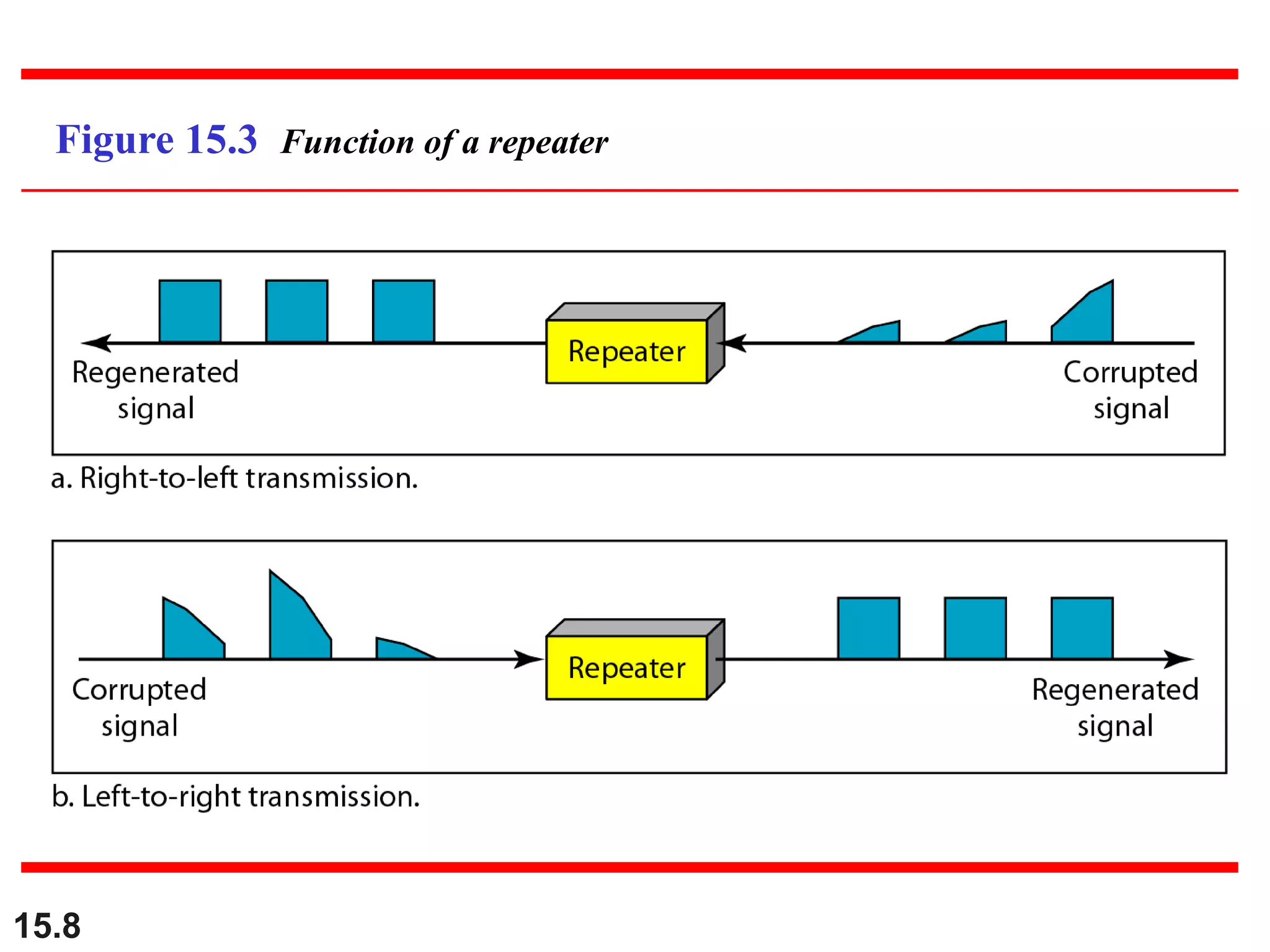
Connecting LANs,
Backbone Networks,
and Virtual LANs
15.2
CONNECTING DEVICES
In this section, we divide connecting devices into five
different categories based on the layer in which they
operate in a network.
Passive Hubs
Active Hubs
Bridges
Two-Layer Switches
Routers
Three-Layer Switches
Gateways
15.3
Five categories of connecting devices
15.4
A repeater connecting two segments of a LAN
15.5
A repeater connects segments of a LAN.
Note
15.6
A repeater forwards every frame;
it has no filtering capability.
Note
15.7
A repeater is a regenerator,
not an amplifier.
(same signal strength, bit for bit copy)
Note
15.8
Figure 15.3 Function of a repeater
15.9
Figure 15.4 A hierarchy of hubs
15.10
A bridge checks MAC addresses. It has
a table used in filtering decisions
(Forward? Drop?). The table shows the
map between MAC addresses and ports.
Note
15.11
Figure 15.5 A bridge connecting two LANs
15.12
A bridge does not change the physical
(MAC) addresses in a frame.
Note
15.13
Figure 15.6 A learning bridge and the process of learning
15.14
Figure 15.7 Loop problem in a learning bridge
15.15
Use spanning three in graph theory to
avoid loop topology. Spanning tree is a
graph without loop.
Note
15.16
Figure 15.11 Routers (three-layer switch)
connecting independent LANs and WANs
15.17
15-2 BACKBONE NETWORKS
A backbone network allows several LANs to be
connected. In a backbone network, no station is
directly connected to the backbone; the stations are
part of a LAN, and the backbone connects the LANs.
Bus Backbone
Star Backbone
Connecting Remote LANs
Topics discussed in this section:
15.18
In a bus backbone, the topology
of the backbone is a bus.
Note
15.19
Figure 15.12 Bus backbone
15.20
In a star backbone, the topology of the
backbone is a star;
the backbone is just one switch.
Note
15.21
Figure 15.13 Star backbone
15.22
Figure 15.14 Connecting remote LANs with bridges
15.23
15-3 VIRTUAL LANs
We can roughly define a virtual local area network
(VLAN) as a local area network configured by
software, not by physical wiring.
Membership
Configuration
Communication between Switches
IEEE Standard
Advantages
Topics discussed in this section:
15.24
Figure 15.15 A switch connecting three LANs
Physical wiring makes it hard to
dynamically change group allocation
15.25
Figure 15.16 A switch using VLAN software
15.26
Figure 15.17 Two switches in a backbone using VLAN software
Good for a company with two separate buildings
15.27
VLANs create broadcast domains.
Note
VLAN: Membership
 Switch port Numbers
 MAC Address
 IP Address
 Multicast IP Address
 Combination
15.28
VLAN Configuration
 Manually
 Automatic
 Semiautomatic
15.29
VLAN: Communication between
switches
 Table maintenance
 Frame tagging
 Extra header added to MAC frame
 Time-Division Multiplexing (TDM)
15.30
VLAN: Advantages
 Cost and time reduction
 Creating Virtual Work Groups
 Security
 Separation of broadcast messages
15.31

connecting devices.ppt