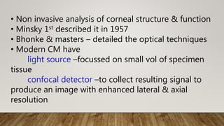
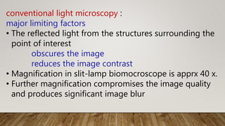
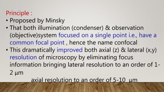
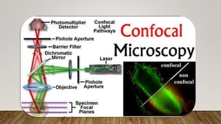
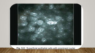
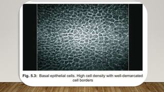
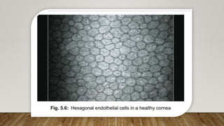
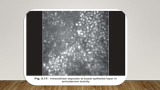
CONFOCAL
MICROSCOPY
Dr.M.Dinesh
• Non invasive analysis of corneal structure & function
• Minsky 1st described it in 1957
• Bhonke & masters – detailed the optical techniques
• Modern CM have
light source –focussed on small vol of specimen
tissue
confocal detector –to collect resulting signal to
produce an image with enhanced lateral & axial
resolution
conventional light microscopy :
major limiting factors
• The reflected light from the structures surrounding the
point of interest
obscures the image
reduces the image contrast
• Magnification in slit-lamp biomocroscope is apprx 40 x.
• Further magnification compromises the image quality
and produces significant image blur
.
Principle :
• Proposed by Minsky
• That both illumination (condenser) & observation
(objective)system focused on a single point i.e., have a
common focal point , hence the name confocal
• This dramatically improved both axial (z) & lateral (x,y)
resolution of microscopy by eliminating focus
information bringing lateral resolution to an order of 1-
2 μm
axial resolution to an order of 5-10 μm
• This allows magnification upto 600x
• It is necessary to rapidly scan the focal point across
the sample & reconstruct the image to allow a real
time on screen view bec field of view is limited
Types of confocal microscope
1.Tandem scanning confocal microscope
• Thousands of light beams are moved over the
fixed object ,generating high scan rate
• These parallel beams are generated by nipkow
wheel- a disc with thousands of pin holes
spinning at high speed
• These apertures are arranged in tandem i.e.,
diametrically opp pairs
• Light passes though one pinhole and is then reflected
back through corresponding pinhole situated opposite
• The high speed of rotation of disc enables light beam to
scan full field of view many times a sec,
thus producing a real time image
2.The scanning slit confocal microscope :
• Uses a light source with
one dimensional spot scanning instead of
two dimensional spot scanning
3.The confocal laser scanning microscope :
• Uses laser beam that generates a monochromatic
,intense sharply focussed & coherent light .
• A novel digital confocal laser scanning microscope
–combination of Heidleberg retina tomography +
-Rostock cornea module
• The laser scanning microscope has
computer controlled hydraulic linear scanning device
water contact objective &
diode laser beam 670nm (light source)
• The rostock scanning laser confocal microscope
provides reproducible images of High resolution
with uniform illumination & precise depth
measurements
OPTICS :
• A halogen light source passes through movable slits
(Nipkow disk).
• A condenser lens (front lens) projects the light to the
cornea.
• Only a small area inside the cornea is illuminated to
minimize the light scattering.
• The reflected light passes through the front lens
again and is directed to another slit of same size
via beam-splitter.
• Finally, the image is projected onto a highly
sensitive camera and displayed on a computer
monitor
• The confocal microscope utilizes a transparent
viscous sterile gel that is interposed b/w front lens
and cornea to eliminate the optical interface with 2
different refractive indices.
• The front lens works on ‘Distance Immersion
Principle’.
• The working distance (distance between front lens &
cornea) is 1.92 mm.
• The back and forth movement of the front lens
enables scanning of the entire cornea starting from
AC and corneal endothelium to superficial corneal
epithelium.
• Use of standard X40 immersion lens gives magnified
cellular detail and an image field of 440 *330 μm.
• X20 lens delivers wide field but less distinct cell
morphology.
• Newer model (Confoscan 2.0) captures 350 images
per examination at a rate of 25 frames per second.
• Thickness of the captured layers varies from 3–5
microns
depending on scanning slit characteristics
• Every recorded image is characterized by its position
on the ‘Z’ axis of the cornea.
• Every time a confocal scan is performed, a graphic
shows the depth coordinate on the ‘Z’ axis and the
level of reflectivity on the ‘Y’ axis.
• The graphic also displays the distance between two
images along the anteroposterior line.
• This simultaneous graphic recording is called ‘Z’ scan
graphic.
• The reflectivity on ‘Z’ scan is entirely dependent on
the tissue being scanned.
• A transparent tissue -low reflectivity
• opaque layer -higher reflectivity.
• A typical ‘Z’ scan of entire normal cornea shows
• corneal endothelium -maximum reflectivity
• epithelium -intermediate
reflectivity
• stroma -lowest reflectivity
• Thus, confocal microscopy can perform
• corneal pachymetry or measure
the distance between two corneal layers
Confocal Microscopy of Normal Cornea
• visualize the
• corneal endothelium,
• stroma,
• subepithelial nerve plexus and
• epithelial layers distinctly.
• Limitations - non-visualization of
• normal Bowman’s layer and
• Descemet’s membrane since these
structures are transparent to this microscope.
• .
•
• it is possible to view BM & DM when
pathologically involved.
• Eyes with corneal opacity or edema can also be
successfully scanned
• The quality of image depends on
• Centration of the light beam,
• Stability of the eye, and
• Optimum brightness of the illumination
Epithelium
• Corneal epithelium has five to six layers.
• Superficial (2–3 layers): flat cells
• Intermediate (2–3 layers): polygonal cells
• Basal cells (single layer): cylindrical cells
Superficial epithelial cells appear as
-flat polygonal cells with well-defined border,
-prominent nuclei and uniform density of
cytoplasm. -nuclei brighter than surrounding
cytoplasm and -associated with peri-nuclear
hypodense ring
Intermediate epithelial cells
-Similar as superficial layers but
-nuclei - not prominent.
Basal cell layers
-smaller in size
-appear denser than other two layers
(Fig. 5.2).
(Fig. 5.3).
ophthalmic division of trigeminal nerve
Lacrimal nasociliary frontal
long ciliary nerve
form a circular plexus at the limbus
from this Radial nerve fibers run deep into the
stroma to form deep corneal plexus.
Subepithelial Nerve Plexus
deep vertical fibers derive from deep corneal plexus to
run anteriorly to form sub-basal and subepithelial nerve
• Small nerve fibers from sub-basal plexus terminate at
the superficial epithelium
• nerve fibers appear bright and well contrasted
against a dark background
• Confocal microscopy can visualize
orientation,
tortuosity,
width,
branching pattern and any
abnormality of the corneal nerves.
(Fig. 5.4).
Subepithelial nerve fibers
Stroma
90% of total corneal thickness. has three components:
• Cellular stroma:
-Composed of keratocytes
-5% of entire stroma.
• Acellular stroma:
-90–95% of stroma.
-main component -collagen(I, III, IV) &
interstitial substances.
• Neurosensory stroma: stromal nerve plexus and
fibers originating from it.
• keratocyte concentration
-higher in the anterior stroma and
-progressively decreases towards the deep
stroma.
• the keratocyte count
-1000 cells/mm² in anterior stroma
-700 cells/mm² in the posterior stroma.
• Confocal image of stroma shows
-multiple irregularly oval, round or bean-shaped
keratocyte nuclei well contrasted against dark acellular
matrix
• keratocyte nuclei
Anterior stromal -rounded bean-shaped
Posterior stroma - irregularly oval.
• A bright highly reflective keratocyte represents
a metabolically activated keratocyte of a healthy
cornea.
• In a normal healthy cornea, collagen fibers and
interstitial substances appear transparent to
confocal microscope and impossible to visualize.
• It is possible to identify stromal nerve fibers in anterior
and mid stroma.
• Nerve fibers belong to deep corneal plexus and
appear as linear bright thick lines.
• The stromal nerve fiber thickness is greater than
epithelial nerves.
• Occasionally, nerve bifurcations are also clearly visible
(Fig. 5.5).
Stromal keratocytes with bright oval-shaped nuclei
Endothelium
• Non-innervated single layer of cells at posterior part
of cornea.
• Endothelial cell density is maximal at birth and
progressively declines with age.
• Normal endothelial cell count varies from 2400 to
3000 cells/mm² (average 2700 cells/mm²)
• cornea can still maintain the integrity till the cell
count declines below 300-500 cells/mm²
• Homogeneous hexagonal cells with uniform size and
shape represent healthy endothelial cells.
• Increasing age and endothelial assault cause
pleomorphism and polymegathism.
• Confocal microscopy easily appear as bright
hexagonal and polygonal cells with unrecognizable
nucleus.
• The cell borders are represented by a thin, non-
reflective dark line
• A X20 objective lens provides wide field with less
magnification, we can perform cell count and study
the minute details of cellular morphology.
(Fig. 5.6).
Confocal microscopy in corneal pathologies
Keratoconus :
• Morphological changes in keratoconus are mostly
confined to the corneal apex and depend on the
severity of the disease.
• Rest of the cornea may appear normal.
• Superficial epithelial cells
- typical polygonal shape lost
-distorted and elongated in an oblique direction
with highly reflective nuclei
-Cell borders are not distinguishable.
• Basal epithelial loss as evident by a linear dark
non-reflective patch
• sub-basal nerve fibers are curved and take the
course of stretched overlying epithelium.
• stromal changes characteristic multiple ‘striae’
represented by thin hyporeflective lines oriented
vertically, horizontally or obliquely (confocal
representation of Vogt’s striae).
• Advanced keratoconus
-keratocyte concentration is reduced in anterior
stroma.
-shape of keratocyte - altered.
-Occasionally, highly reflective bodies with
tapering ends in anterior stroma near the apex (may be
d/t altered
keratocytes).
• Corneal endothelium - pleomorphism and
polymegathism
Fig. 5.7).
(Fig. 5.8).
Corneal Dystrophies :
Granular Dystrophy
• AD b/l non-inflammatory condition
• d/t deposition of eosinophilic hyaline deposits in
stroma. specifically affects central cornea DV
• Initially, the lesions in superficial stroma
• Later stages can involve posterior stroma
• Confocal microscopy reveals highly reflective, bright,
dense structures in the anterior and mid-stroma.
• Keratocytes are not involved.
• Depth of stromal involvement ascertained by using
‘Z’ scan function.
• added advantage over other contemporary
investigations that enables surgeon to plan for
surgical modalities.
• Confocal microscopy is also useful in
differential diagnosis and follow-up of the disease
Posterior Polymorphous Dystrophy
• rare inherited b/l disorder of posterior layer of
cornea.
• The characteristic endothelial changes are small
vesicles
or areas of geographic lesions.
• Endothelial cells lining of the posterior surface of the
cornea have epithelial like features.
• These cells can also cover TM glaucoma
• Most severe cases may develop corneal edema due
to compromised pump function of the endothelial
Confocal microscopy shows
• multiple round vesicles at the level of DM &
endothelium.
• large dark cystic endothelial cells
• endothelial cells surrounding the lesion appear large
and
distorted
Fuchs Endothelial Dystrophy :
• chronic b/l hereditary disorder of corneal
endothelium
• MC in females after 50yrs.
• There is a loss of endothelial cells that results in
deposition of collagen materials in Descemet’s
membrane (guttata).
• Corneal guttata is the hallmark of this disease.
endothelium integrity diturbed Corneal edema
• advanced ds edema progresses to involve the
anterior cornea bullous keratopathy
• CM is useful to visualize the corneal guttata.
• This technique has a distinct advantage over
conventional specular microscopy that fails to
visualize
endothelium when there is significant corneal
edema
• corneal guttata appears dark with bright central
reflex
• Advanced ds endothelial cell borders – distorted
• In the early stages of bullous keratopathy,
intraepithelial edema distorted cellular
morphology with increased reflectivity.
(Fig. 5.9).
Laser in situ Keratomileusis
Confocal scan is useful in evaluation of following
parameters:
• Corneal flap thickness
• Interface study
– Healing process
– Inflammatory response
– Abnormal deposits
• Corneal nerve fiber regeneration
• Residual stromal thickness
• flap thickness - measuring distance b/w
high reflective spike from the front surface of the
cornea & low reflective interface
• The interface usually appears as a hyporeflective
space in
between relatively hyperreflective cellular stroma.
• Typically, keratocyte concentration is lower than
normal in the interface.
• Bright particles and microstriae are consistently
visible in the interface.
• bright particles most probably originate from
microkeratome blade and represented by highly
(Fig. 5.10).
(Fig. 5.11).
Infectious Keratitis
Acanthamoeba keratitis :
• CM - non-invasive technique to diagnose
• Internal structures of Acanthamoeba along with
vacuoles are also visible.
• On CM Acanthamoeba appear as round or ovoid
highly reflective structures ranging in size from 10 to
25 µm, which is larger than leucocytes
• Sometime double-wall cystic forms of the parasite
also
well visualized .Acanthamoeba are smaller , more
iridescent than epithelial cells and keratocyte nuclei
(Fig. 5.13).
Fig. 5.12).
Mycotic keratitis
• CM not only for rapidly diagnosing fungal keratitis
but also to monitor the anti-fungal therapy
• On CM mycotic organisms appear as
• thin, extensively branching, beaded filaments
and
• round to oval spores also can be found
• In vivo confocal microscopy offers either of the
morphologic features of mycotic keratitis such as
(a) Branching hyper-reflective structures,
(b) The long line hyper-reflective structures,
(c) The short rod hyper-reflective structures &
(d) Round to oval structures (spores).
• The hyphae must not be confused with corneal
nerves, which appear regular, elongated and uniform
with sharp margins.
(Fig. 5.14).
Corneal Grafts
• CM
• used to assess the donor cornea
• evaluating endothelial cell in eyes with stromal
edema
• Endothelial morphology - pleomorphism and
polymegathism
• a bright pre-endothelial deposit appears, the
significance of which is not yet known
• Evidence of Reinnervation after grafting
Graft rejection :
• Confocal features of
• epithelial rejection - distorted basal epithelial cells
with
altered subepithelial reflectivity.
• Subepithelial rejection -discrete opacities epithelial
layer
• Endothelial rejection -
coexistence of normal looking and degenerated
endothelial cells,
focal endothelial cell lesions and bright highly
reflective
(Fig. 5.15).
Intracorneal Deposits
They can involve various layers of cornea
Exogenous sources:
• Long-term use of contact lenses
• Refractive surgery
• Vitreoretinal surgery using silicone oil
• Drugs: Amiodarone, Chloroquine
Endogenous sources:
• Wilson’s disease
• Hyperlipidemia
• Fabry’s disease
• Hemosiderosis
Vortex Keratopathy
• Also known as cornea verticillata is characterized by
whorl-like corneal epithelial deposits.
• It can be induced drugs,
e.g. amiodarone (used for cardiac arrythmias)
and anti-malarials (chloroquine, hydroxychloroquine).
• Clinically, vortex keratopathy is manifested as golden-
brown opacities at the inferior corneal epithelium.
• On electron microscopy, they appear as
intracytoplasmic lysosome-like lamellar inclusion
bodies located at the basal epithelial layer
• CM demonstrates involvement of entire cornea,
although vortex keratopathy is primarily a corneal
epithelial pathology.
• The characteristic features are presence of highly
reflective, bright intracellular deposits at the basal
epithelial
layer.
• Overlying epithelium is usually normal.
• In advanced case microdeposits seen in to the stroma
and endothelium.
• Stromal keratocyte density is often reduced
KERATOMETRY
Kerato”- cornea
“metry”-measurement of
Definition:
• Keratometry is measurement of curvature of the
anterior surface of cornea across a fixed chord
length, usually 2-3 mm, which lies within the
optical spherical zone of cornea.
• Expressed in Dioptric power.
• Keratometer also called as Ophthalmometer.
YEARS INVENTORS
1691 Christoph Scheiner –Description of corneal curvature
-Compared size of the bars in a window-lens & cornea
1796 Jesse Ramsden- Inventor of 1st model of keratometer
with 3 essential elements
1854 Helmholtz improved Ramsden’s design for laboratory
use
1881 Javal & Schiotz modified Helmholtz’s instrument for
clinical use
1980 Development of autorefractometer
Principle :
• Keratometry is based on the fact that
the anterior surface of the cornea acts as a convex
mirror & the size of the image formed varies with its
curvature.
• Greater the curvature of cornea, lesser is the image size.
• Therefore, from the size of the image formed by the
anterior surface of cornea (1st Purkinje image) , the
radius of curvature of cornea calculated as below:
• Optical principle involved is the relationship between
the size of an object and size of the image of that
object reflected from surface.
• Radius of curvature is determined by the apparent size
of the image of bright object (mires) viewed by the
reflection from anterior corneal surface which acts as a
convex mirror.
r = 2 x h1/h
• r= radius of curvature, h=height of object, h1=height of
the image
D= (n1-n) /r x 1000
• n1= refractive index of cornea (1.337),n=refractive index
Principles of Keratometry AB is the object and A' B' is
the image. By measuring the size of the object and
image, curvature of the convex surface can be
calculated
Keratometer is based on 2 concepts:
• Fixed object size with variable image size
(Variable doubling)
Eg. Bausch and Lomb keratometer
• Fixed image size with variable object size
(Fixed doubling)
Eg. Javal- Schiotz keratometer
Doubling principle:
• Because of involuntary eye movement image
formed on cornea would be constantly moving.
• To overcome this Ramsden devoloped Doubling
technique.
• A prism is introduced into the optical system so
that 2 images are formed .
• The prism is moved until the images touch each
other.
• Depending on the position of prism, if distance
doubling
Basically, there are two types of keratometer:
• Manual keratometer
• Auto keratometer
•PRINCIPLE:
“Constant object size
and variable image size”.
BAUSCH AND LOMB KERATOMETER
PARTS
Optical system of keratometer
OPTICAL SYSTEM AND OTHER PARTS :
Object: Circular mire with two plus & two minus signs.
oLamp illuminates the mire by means
of a diagonally placed mirror.
oLight from the mire strikes the patient’s cornea &
produces a diminished image behind it.
oThis image becomes the object for the remainder of
optical system.
2. Objective lens:
• Focuses light from the image of the mire (new
object) along the central axis.
3. Diaphragm and doubling prisms:
• 4 aperture diaphragm is situated near objective lens.
• Beyond the diaphragm are two doubling prisms,
one with its base up & other with its base out.
• Prisms can be moved independently, parallel to the
central axis of instrument.
Light passing through left
aperture of diaphragm is made to
deviate above the central optical
axis by a base-up prism.
Light passing through right
aperture is deviated by base –out
prism, placing the second image
to the right of the central axis.
Light passing through upper &
lower apertures does not pass
through either prism & an image
is produced on the axis.
• Total area of upper & = Area of each of
lower apertures the other two apertures
• Therefore, brightness of the images is equal.
• Upper and lower apertures also act as Scheiner’s
disc doubling the central image, whenever the
instrument is not focused precisely on central mire
image.
• Thus, image-doubling mechanism is unique in
Bausch and Lomb keratometer, in that double
images are produced side by side as well as at 900
from each other.
This allows the measurement of the power of cornea in
two meridia, without rotating the instrument.
Therefore, it is also known as ‘one-position
keratometer’.
4. Eyepiece lens:
oEnables examiner to observe magnified view of the
doubled image.
• PROCEDURE OF KERATOMETRY:
1. Instrument adjustment:
Instrument is calibrated before use
White paper held in front of objective lens & a
black line is focused sharply on it
Keratometer is then calibrated with steel balls
Steel ball of known radius of curvature is placed
before keratometer & its value is set on the scale or
dial
Mires are focused by clockwise & anticlockwise
movement of eyepiece through trial & error
When mires are in focus, the calibration is complete.
2. Patient adjustment:
o Seated in front of the instrument.
o Chin on chin rest & head against head rest.
o Eye not being examined is covered with occluder.
o Chin is raised or lowered till patient’s pupil & projective knob
are at the same level.
3. Focusing of mire:
oMire is focused in the centre of cornea.
Patient’s view of
mire
First view seen by the examiner.
Note that the central image is doubled,
indicating that instrument is not correctly
focused on the corneal image of the mire.
4. Measurement of corneal curvature:
oInstrument is correctly focused on corneal image so that
central image is no longer doubled.
To measure curvature in
horizontal meridian, plus
signs of central & left
images are superimposed
using horizontal
measuring control.
To measure curvature in
vertical meridian, minus
signs of central & upper
images are coincided with
the help of vertical
measuring control.
In presence of oblique
astigmatism, two plus
signs will not be
aligned.Entire instrument
rotated till they are
aligned.
Corneal radius of
Power is then
measured.
OBLIQUE ASTIGMATISM
• RECORDING OF THE CORNEAL CURVATURE:
INTERPRETATION OF FINDINGS
Remember that it is the power
meridian, NOT the axis, being
recorded in keratometry.
Spherical cornea
• No difference in power b/w 2 principal meridia
• Mires seen as perfect sphere.
Astigmatism
• Difference in power b/w 2 principal meridia.
• Horizontally oval mires in WTR astigmatism.
• Vertically oval mires in ATR astigmatism.
• Oblique astimatism principal meridia b/w 300-
600 & 120-1500.
Irregular anterior corneal surface
• Irregular mires.
• Doubling of mires.
Keratoconus
• Pulsating mires(Inclination & jumpimg of mires on
attempt to adjust the mires).
• Minification of mires in advanced cases (K >52 D)
due to increased amount of myopia.
• Oval mires due to large astigmatism.
• Irregular,wavy & distorted mires in advanced
keratoconus.
RANGE OF KERATOMETER:
• Range  36.00 to 52.00 D
• Normal values  44.00 to 45.00 D
• To increase the range  Place +1.25 D lens in front of
the aperture to extend range to 61 D.
 ADD 9 D
• Place -1.00 D lens in front of the aperture to extend
range to 30 D.
 SUBTRACT 6 D
•PRINCIPLE:
“Variable object size and
constant image size”.
JAVAL –SCHIOTZ KERATOMETER
• OPTICAL SYSTEM AND PARTS:
1.Object:
oConsists of two mires (A & B), mounted on an arc on which they can be
moved synchronously.
oSince the two mires together form the object, the variable size is
attained by their movement.
OPTICAL SYSTEM OF KERATOMETER
One
mireStepped,
has green filter
Other mire
Rectangular, has red
filter
oMires divided horizontally through the centre.
oThey are illuminated by small lamps.
oImage of these mires formed by patient’s cornea (1st
Purkinje image) acts as an object for the rest of the
optical system of the keratometer.
2.Objective lens & doubling prism:
oForms double image of the new object.
oDoubling prism used  Wollaston type.
oProduces fixed image doubling by birefringent (double
refracting) characteristic of material of which it is made.
3. Eyepiece lens:
oEnables examiner to observe magnified view of the
doubled image.
PROCEDURE OF KERATOMETRY:
1.Instrument adjustment:
oWhite paper held in front of the objective piece &
black line focused on it.
oThen instrument is calibrated to make it ready for
use.
2.Patient adjustment
3.Adjustment of mires:
oMires are focused in the centre of patient’s cornea.
Patient’s view of
mires
Examiner’s view of doubled
mire
4.Recording of keratometric readings:
oOnly central pair of images is used when measurements are
made.
oWhen two control images just meet, the scales associated with
the mire separation indicate the correct corneal radius & dioptric
power of the cornea.
Radius of curvature first
found in one meridian.
Then entire optical system
rotated 900 about its central
axis.
Measurement of radius of
curvature in second meridian
which is perpendicular to 1st
one is then made in similar
way.
• When corneal astigmatism is present
 Overlapping of mires or they may
move further apart.
• Since stepped mire (staircase
pattern) is green & rectangular mire
is red, area of overlap appears
whitish.
• Each step of mire  1 D of corneal
power ,thus the number of steps
overlapped gives approximate
degree of astigmatism.
• When oblique astigmatism is present
Mires are
horizontal,central bisecting
lines of images are not
aligned.
Instrument is rotated until
the control lines are
aligned.
Scale associated with
instrument rotation
indicates, in degrees, one
meridian of oblique
astigmatism.
Corneal radius or power is then measured in this meridian &
also in the meridian 900 to it as usual.
1. Helps in measurement of corneal astigmatic error.
oDifference in power between two principal meridians is
the amount of corneal astigmatism.
oIn Optometry, astigmatism is corrected by minus
cylinder lens.
oFrom K readings, meridian of least refracting power
indicates the position of minus axis of correcting
CLINICAL USES OF KERATOMETERS
Eg 1. OD 42.50D at 180 / 44.50D at 90
 Corneal astigmatism = 2.00D
 Correcting cylinder = -2.00DC x 180
 WTR astigmatism
Eg 2. OD 42.75D at 180 / 42.00D at 90
 Corneal astigmatism = 0.75D
 Correcting cylinder = -0.75DC x 90
 ATR astigmatism
2. Helps to estimate radius of curvature of the anterior
surface of cornea  Use in contact lens fitting.
3.Monitors shape of the cornea 
Keratoconus/Keratoglobus
4.Assess refractive error in cases of hazy media.
5.IOL power calculation.
6.To monitor pre- & post-surgical astigmatism.
7.Used for differential diagnosis of axial versus curvatural
anisometropia.
Limitations of keratometry :
• Measurements of keratometer based on false
assumption that cornea is a symmetrical spherical
or spherocylindrical structure,with 2 principal
meridia separated from each other by 900
• Measures refractive status of small central cornea
(3-4 mm)
• Loses accuracy when measuring very flat or very
steep cornea
• Small corneal irregularities preclude use of
keratometer due to irregular astigmatism.
• One-position instruments assume regular
astigmatism.
• Distance to focal point is approximated by distance to
image.
• Other limitationUse of para-axial optics to
calculate surface power.
Improper
calibration
Faulty
positioning of
patient
Improper
fixation by
patient
Accomodat-
ive fluctuation
by examiner
Localized
corneal
distortion
Excessive
tearing
Abnormal lid
position
Improper
focusing of
corneal image
SOURCES OF ERROR IN KERATOMETRY
SURGICAL/OPERATING KERATOMETER
• Attached to operating microscope.
• Helpful in monitoring astigmatism during corneal
surgery.
• Accuracy limited:
1. Difficulty in aligning patients visual axis &
keratometer’s optical axis.
2. Calibrated for a fixed distance from anterior cornea.
3. Different microscope objective lenses result in
different focal lengths & therefore different working
distance.
AUTOMATED KERATOMETER
• Focuses reflected corneal image on to an
electronic photosensitive device, which
instantly records the size & computes the
radius of curvature.
• Target mires are illuminated with infrared
light, & an infrared photodetector is used.
ADVANTAGES:
• Compact device
• Very short time consuming
• Comparatively easy to operate
Availability of autokeratometer:
oEither available alone or more commonly in association
with autorefractometers as autokeratorefractometers.
Eg: Nidek ARK 2000-S autokeratorefractometer
oAutomated keratometry can be performed using
following instruments:
1. The IOL master
2. Pentacam
3. Orbscan
4. Corneal topographer
THAN Q

Confocal microscopy dinesh

  • 1.
  • 2.
    • Non invasiveanalysis of corneal structure & function • Minsky 1st described it in 1957 • Bhonke & masters – detailed the optical techniques • Modern CM have light source –focussed on small vol of specimen tissue confocal detector –to collect resulting signal to produce an image with enhanced lateral & axial resolution
  • 3.
    conventional light microscopy: major limiting factors • The reflected light from the structures surrounding the point of interest obscures the image reduces the image contrast • Magnification in slit-lamp biomocroscope is apprx 40 x. • Further magnification compromises the image quality and produces significant image blur .
  • 4.
    Principle : • Proposedby Minsky • That both illumination (condenser) & observation (objective)system focused on a single point i.e., have a common focal point , hence the name confocal • This dramatically improved both axial (z) & lateral (x,y) resolution of microscopy by eliminating focus information bringing lateral resolution to an order of 1- 2 μm axial resolution to an order of 5-10 μm
  • 5.
    • This allowsmagnification upto 600x • It is necessary to rapidly scan the focal point across the sample & reconstruct the image to allow a real time on screen view bec field of view is limited
  • 8.
    Types of confocalmicroscope 1.Tandem scanning confocal microscope • Thousands of light beams are moved over the fixed object ,generating high scan rate • These parallel beams are generated by nipkow wheel- a disc with thousands of pin holes spinning at high speed • These apertures are arranged in tandem i.e., diametrically opp pairs
  • 9.
    • Light passesthough one pinhole and is then reflected back through corresponding pinhole situated opposite • The high speed of rotation of disc enables light beam to scan full field of view many times a sec, thus producing a real time image
  • 12.
    2.The scanning slitconfocal microscope : • Uses a light source with one dimensional spot scanning instead of two dimensional spot scanning
  • 13.
    3.The confocal laserscanning microscope : • Uses laser beam that generates a monochromatic ,intense sharply focussed & coherent light . • A novel digital confocal laser scanning microscope –combination of Heidleberg retina tomography + -Rostock cornea module • The laser scanning microscope has computer controlled hydraulic linear scanning device water contact objective & diode laser beam 670nm (light source)
  • 14.
    • The rostockscanning laser confocal microscope provides reproducible images of High resolution with uniform illumination & precise depth measurements
  • 15.
    OPTICS : • Ahalogen light source passes through movable slits (Nipkow disk). • A condenser lens (front lens) projects the light to the cornea. • Only a small area inside the cornea is illuminated to minimize the light scattering.
  • 16.
    • The reflectedlight passes through the front lens again and is directed to another slit of same size via beam-splitter. • Finally, the image is projected onto a highly sensitive camera and displayed on a computer monitor
  • 17.
    • The confocalmicroscope utilizes a transparent viscous sterile gel that is interposed b/w front lens and cornea to eliminate the optical interface with 2 different refractive indices. • The front lens works on ‘Distance Immersion Principle’. • The working distance (distance between front lens & cornea) is 1.92 mm. • The back and forth movement of the front lens enables scanning of the entire cornea starting from AC and corneal endothelium to superficial corneal epithelium.
  • 18.
    • Use ofstandard X40 immersion lens gives magnified cellular detail and an image field of 440 *330 μm. • X20 lens delivers wide field but less distinct cell morphology. • Newer model (Confoscan 2.0) captures 350 images per examination at a rate of 25 frames per second. • Thickness of the captured layers varies from 3–5 microns depending on scanning slit characteristics
  • 19.
    • Every recordedimage is characterized by its position on the ‘Z’ axis of the cornea. • Every time a confocal scan is performed, a graphic shows the depth coordinate on the ‘Z’ axis and the level of reflectivity on the ‘Y’ axis. • The graphic also displays the distance between two images along the anteroposterior line. • This simultaneous graphic recording is called ‘Z’ scan graphic. • The reflectivity on ‘Z’ scan is entirely dependent on the tissue being scanned.
  • 20.
    • A transparenttissue -low reflectivity • opaque layer -higher reflectivity. • A typical ‘Z’ scan of entire normal cornea shows • corneal endothelium -maximum reflectivity • epithelium -intermediate reflectivity • stroma -lowest reflectivity • Thus, confocal microscopy can perform • corneal pachymetry or measure the distance between two corneal layers
  • 21.
    Confocal Microscopy ofNormal Cornea • visualize the • corneal endothelium, • stroma, • subepithelial nerve plexus and • epithelial layers distinctly. • Limitations - non-visualization of • normal Bowman’s layer and • Descemet’s membrane since these structures are transparent to this microscope. • . •
  • 22.
    • it ispossible to view BM & DM when pathologically involved. • Eyes with corneal opacity or edema can also be successfully scanned • The quality of image depends on • Centration of the light beam, • Stability of the eye, and • Optimum brightness of the illumination
  • 23.
    Epithelium • Corneal epitheliumhas five to six layers. • Superficial (2–3 layers): flat cells • Intermediate (2–3 layers): polygonal cells • Basal cells (single layer): cylindrical cells
  • 24.
    Superficial epithelial cellsappear as -flat polygonal cells with well-defined border, -prominent nuclei and uniform density of cytoplasm. -nuclei brighter than surrounding cytoplasm and -associated with peri-nuclear hypodense ring Intermediate epithelial cells -Similar as superficial layers but -nuclei - not prominent. Basal cell layers -smaller in size -appear denser than other two layers
  • 26.
  • 27.
    ophthalmic division oftrigeminal nerve Lacrimal nasociliary frontal long ciliary nerve form a circular plexus at the limbus from this Radial nerve fibers run deep into the stroma to form deep corneal plexus. Subepithelial Nerve Plexus deep vertical fibers derive from deep corneal plexus to run anteriorly to form sub-basal and subepithelial nerve
  • 28.
    • Small nervefibers from sub-basal plexus terminate at the superficial epithelium • nerve fibers appear bright and well contrasted against a dark background • Confocal microscopy can visualize orientation, tortuosity, width, branching pattern and any abnormality of the corneal nerves.
  • 29.
  • 30.
    Stroma 90% of totalcorneal thickness. has three components: • Cellular stroma: -Composed of keratocytes -5% of entire stroma. • Acellular stroma: -90–95% of stroma. -main component -collagen(I, III, IV) & interstitial substances. • Neurosensory stroma: stromal nerve plexus and fibers originating from it.
  • 31.
    • keratocyte concentration -higherin the anterior stroma and -progressively decreases towards the deep stroma. • the keratocyte count -1000 cells/mm² in anterior stroma -700 cells/mm² in the posterior stroma. • Confocal image of stroma shows -multiple irregularly oval, round or bean-shaped keratocyte nuclei well contrasted against dark acellular matrix
  • 32.
    • keratocyte nuclei Anteriorstromal -rounded bean-shaped Posterior stroma - irregularly oval. • A bright highly reflective keratocyte represents a metabolically activated keratocyte of a healthy cornea. • In a normal healthy cornea, collagen fibers and interstitial substances appear transparent to confocal microscope and impossible to visualize.
  • 33.
    • It ispossible to identify stromal nerve fibers in anterior and mid stroma. • Nerve fibers belong to deep corneal plexus and appear as linear bright thick lines. • The stromal nerve fiber thickness is greater than epithelial nerves. • Occasionally, nerve bifurcations are also clearly visible
  • 34.
    (Fig. 5.5). Stromal keratocyteswith bright oval-shaped nuclei
  • 35.
    Endothelium • Non-innervated singlelayer of cells at posterior part of cornea. • Endothelial cell density is maximal at birth and progressively declines with age. • Normal endothelial cell count varies from 2400 to 3000 cells/mm² (average 2700 cells/mm²) • cornea can still maintain the integrity till the cell count declines below 300-500 cells/mm²
  • 36.
    • Homogeneous hexagonalcells with uniform size and shape represent healthy endothelial cells. • Increasing age and endothelial assault cause pleomorphism and polymegathism. • Confocal microscopy easily appear as bright hexagonal and polygonal cells with unrecognizable nucleus. • The cell borders are represented by a thin, non- reflective dark line • A X20 objective lens provides wide field with less magnification, we can perform cell count and study the minute details of cellular morphology.
  • 37.
  • 38.
    Confocal microscopy incorneal pathologies Keratoconus : • Morphological changes in keratoconus are mostly confined to the corneal apex and depend on the severity of the disease. • Rest of the cornea may appear normal. • Superficial epithelial cells - typical polygonal shape lost -distorted and elongated in an oblique direction with highly reflective nuclei -Cell borders are not distinguishable.
  • 39.
    • Basal epithelialloss as evident by a linear dark non-reflective patch • sub-basal nerve fibers are curved and take the course of stretched overlying epithelium. • stromal changes characteristic multiple ‘striae’ represented by thin hyporeflective lines oriented vertically, horizontally or obliquely (confocal representation of Vogt’s striae).
  • 40.
    • Advanced keratoconus -keratocyteconcentration is reduced in anterior stroma. -shape of keratocyte - altered. -Occasionally, highly reflective bodies with tapering ends in anterior stroma near the apex (may be d/t altered keratocytes). • Corneal endothelium - pleomorphism and polymegathism
  • 41.
  • 42.
  • 43.
    Corneal Dystrophies : GranularDystrophy • AD b/l non-inflammatory condition • d/t deposition of eosinophilic hyaline deposits in stroma. specifically affects central cornea DV • Initially, the lesions in superficial stroma • Later stages can involve posterior stroma
  • 44.
    • Confocal microscopyreveals highly reflective, bright, dense structures in the anterior and mid-stroma. • Keratocytes are not involved. • Depth of stromal involvement ascertained by using ‘Z’ scan function. • added advantage over other contemporary investigations that enables surgeon to plan for surgical modalities. • Confocal microscopy is also useful in differential diagnosis and follow-up of the disease
  • 45.
    Posterior Polymorphous Dystrophy •rare inherited b/l disorder of posterior layer of cornea. • The characteristic endothelial changes are small vesicles or areas of geographic lesions. • Endothelial cells lining of the posterior surface of the cornea have epithelial like features. • These cells can also cover TM glaucoma • Most severe cases may develop corneal edema due to compromised pump function of the endothelial
  • 46.
    Confocal microscopy shows •multiple round vesicles at the level of DM & endothelium. • large dark cystic endothelial cells • endothelial cells surrounding the lesion appear large and distorted
  • 47.
    Fuchs Endothelial Dystrophy: • chronic b/l hereditary disorder of corneal endothelium • MC in females after 50yrs. • There is a loss of endothelial cells that results in deposition of collagen materials in Descemet’s membrane (guttata). • Corneal guttata is the hallmark of this disease. endothelium integrity diturbed Corneal edema • advanced ds edema progresses to involve the anterior cornea bullous keratopathy
  • 48.
    • CM isuseful to visualize the corneal guttata. • This technique has a distinct advantage over conventional specular microscopy that fails to visualize endothelium when there is significant corneal edema • corneal guttata appears dark with bright central reflex • Advanced ds endothelial cell borders – distorted • In the early stages of bullous keratopathy, intraepithelial edema distorted cellular morphology with increased reflectivity.
  • 49.
  • 50.
    Laser in situKeratomileusis Confocal scan is useful in evaluation of following parameters: • Corneal flap thickness • Interface study – Healing process – Inflammatory response – Abnormal deposits • Corneal nerve fiber regeneration • Residual stromal thickness
  • 51.
    • flap thickness- measuring distance b/w high reflective spike from the front surface of the cornea & low reflective interface • The interface usually appears as a hyporeflective space in between relatively hyperreflective cellular stroma. • Typically, keratocyte concentration is lower than normal in the interface. • Bright particles and microstriae are consistently visible in the interface. • bright particles most probably originate from microkeratome blade and represented by highly
  • 52.
  • 53.
  • 54.
    Infectious Keratitis Acanthamoeba keratitis: • CM - non-invasive technique to diagnose • Internal structures of Acanthamoeba along with vacuoles are also visible. • On CM Acanthamoeba appear as round or ovoid highly reflective structures ranging in size from 10 to 25 µm, which is larger than leucocytes • Sometime double-wall cystic forms of the parasite also well visualized .Acanthamoeba are smaller , more iridescent than epithelial cells and keratocyte nuclei
  • 55.
  • 56.
  • 57.
    Mycotic keratitis • CMnot only for rapidly diagnosing fungal keratitis but also to monitor the anti-fungal therapy • On CM mycotic organisms appear as • thin, extensively branching, beaded filaments and • round to oval spores also can be found
  • 58.
    • In vivoconfocal microscopy offers either of the morphologic features of mycotic keratitis such as (a) Branching hyper-reflective structures, (b) The long line hyper-reflective structures, (c) The short rod hyper-reflective structures & (d) Round to oval structures (spores). • The hyphae must not be confused with corneal nerves, which appear regular, elongated and uniform with sharp margins.
  • 59.
  • 60.
    Corneal Grafts • CM •used to assess the donor cornea • evaluating endothelial cell in eyes with stromal edema • Endothelial morphology - pleomorphism and polymegathism • a bright pre-endothelial deposit appears, the significance of which is not yet known • Evidence of Reinnervation after grafting
  • 61.
    Graft rejection : •Confocal features of • epithelial rejection - distorted basal epithelial cells with altered subepithelial reflectivity. • Subepithelial rejection -discrete opacities epithelial layer • Endothelial rejection - coexistence of normal looking and degenerated endothelial cells, focal endothelial cell lesions and bright highly reflective
  • 62.
  • 64.
    Intracorneal Deposits They caninvolve various layers of cornea Exogenous sources: • Long-term use of contact lenses • Refractive surgery • Vitreoretinal surgery using silicone oil • Drugs: Amiodarone, Chloroquine Endogenous sources: • Wilson’s disease • Hyperlipidemia • Fabry’s disease • Hemosiderosis
  • 65.
    Vortex Keratopathy • Alsoknown as cornea verticillata is characterized by whorl-like corneal epithelial deposits. • It can be induced drugs, e.g. amiodarone (used for cardiac arrythmias) and anti-malarials (chloroquine, hydroxychloroquine). • Clinically, vortex keratopathy is manifested as golden- brown opacities at the inferior corneal epithelium. • On electron microscopy, they appear as intracytoplasmic lysosome-like lamellar inclusion bodies located at the basal epithelial layer
  • 66.
    • CM demonstratesinvolvement of entire cornea, although vortex keratopathy is primarily a corneal epithelial pathology. • The characteristic features are presence of highly reflective, bright intracellular deposits at the basal epithelial layer. • Overlying epithelium is usually normal. • In advanced case microdeposits seen in to the stroma and endothelium. • Stromal keratocyte density is often reduced
  • 68.
  • 69.
  • 70.
    Definition: • Keratometry ismeasurement of curvature of the anterior surface of cornea across a fixed chord length, usually 2-3 mm, which lies within the optical spherical zone of cornea. • Expressed in Dioptric power. • Keratometer also called as Ophthalmometer.
  • 71.
    YEARS INVENTORS 1691 ChristophScheiner –Description of corneal curvature -Compared size of the bars in a window-lens & cornea 1796 Jesse Ramsden- Inventor of 1st model of keratometer with 3 essential elements 1854 Helmholtz improved Ramsden’s design for laboratory use 1881 Javal & Schiotz modified Helmholtz’s instrument for clinical use 1980 Development of autorefractometer
  • 72.
    Principle : • Keratometryis based on the fact that the anterior surface of the cornea acts as a convex mirror & the size of the image formed varies with its curvature. • Greater the curvature of cornea, lesser is the image size. • Therefore, from the size of the image formed by the anterior surface of cornea (1st Purkinje image) , the radius of curvature of cornea calculated as below:
  • 73.
    • Optical principleinvolved is the relationship between the size of an object and size of the image of that object reflected from surface. • Radius of curvature is determined by the apparent size of the image of bright object (mires) viewed by the reflection from anterior corneal surface which acts as a convex mirror. r = 2 x h1/h • r= radius of curvature, h=height of object, h1=height of the image D= (n1-n) /r x 1000 • n1= refractive index of cornea (1.337),n=refractive index
  • 74.
    Principles of KeratometryAB is the object and A' B' is the image. By measuring the size of the object and image, curvature of the convex surface can be calculated
  • 75.
    Keratometer is basedon 2 concepts: • Fixed object size with variable image size (Variable doubling) Eg. Bausch and Lomb keratometer • Fixed image size with variable object size (Fixed doubling) Eg. Javal- Schiotz keratometer
  • 76.
    Doubling principle: • Becauseof involuntary eye movement image formed on cornea would be constantly moving. • To overcome this Ramsden devoloped Doubling technique. • A prism is introduced into the optical system so that 2 images are formed . • The prism is moved until the images touch each other. • Depending on the position of prism, if distance doubling
  • 77.
    Basically, there aretwo types of keratometer: • Manual keratometer • Auto keratometer
  • 78.
    •PRINCIPLE: “Constant object size andvariable image size”. BAUSCH AND LOMB KERATOMETER
  • 79.
  • 80.
    Optical system ofkeratometer
  • 81.
    OPTICAL SYSTEM ANDOTHER PARTS : Object: Circular mire with two plus & two minus signs. oLamp illuminates the mire by means of a diagonally placed mirror. oLight from the mire strikes the patient’s cornea & produces a diminished image behind it. oThis image becomes the object for the remainder of optical system.
  • 82.
    2. Objective lens: •Focuses light from the image of the mire (new object) along the central axis. 3. Diaphragm and doubling prisms: • 4 aperture diaphragm is situated near objective lens. • Beyond the diaphragm are two doubling prisms, one with its base up & other with its base out. • Prisms can be moved independently, parallel to the central axis of instrument.
  • 83.
    Light passing throughleft aperture of diaphragm is made to deviate above the central optical axis by a base-up prism. Light passing through right aperture is deviated by base –out prism, placing the second image to the right of the central axis. Light passing through upper & lower apertures does not pass through either prism & an image is produced on the axis.
  • 84.
    • Total areaof upper & = Area of each of lower apertures the other two apertures • Therefore, brightness of the images is equal. • Upper and lower apertures also act as Scheiner’s disc doubling the central image, whenever the instrument is not focused precisely on central mire image. • Thus, image-doubling mechanism is unique in Bausch and Lomb keratometer, in that double images are produced side by side as well as at 900 from each other.
  • 85.
    This allows themeasurement of the power of cornea in two meridia, without rotating the instrument. Therefore, it is also known as ‘one-position keratometer’. 4. Eyepiece lens: oEnables examiner to observe magnified view of the doubled image.
  • 86.
    • PROCEDURE OFKERATOMETRY: 1. Instrument adjustment: Instrument is calibrated before use White paper held in front of objective lens & a black line is focused sharply on it Keratometer is then calibrated with steel balls Steel ball of known radius of curvature is placed before keratometer & its value is set on the scale or dial
  • 87.
    Mires are focusedby clockwise & anticlockwise movement of eyepiece through trial & error When mires are in focus, the calibration is complete. 2. Patient adjustment: o Seated in front of the instrument. o Chin on chin rest & head against head rest. o Eye not being examined is covered with occluder. o Chin is raised or lowered till patient’s pupil & projective knob are at the same level.
  • 88.
    3. Focusing ofmire: oMire is focused in the centre of cornea. Patient’s view of mire First view seen by the examiner. Note that the central image is doubled, indicating that instrument is not correctly focused on the corneal image of the mire.
  • 89.
    4. Measurement ofcorneal curvature: oInstrument is correctly focused on corneal image so that central image is no longer doubled.
  • 90.
    To measure curvaturein horizontal meridian, plus signs of central & left images are superimposed using horizontal measuring control. To measure curvature in vertical meridian, minus signs of central & upper images are coincided with the help of vertical measuring control. In presence of oblique astigmatism, two plus signs will not be aligned.Entire instrument rotated till they are aligned. Corneal radius of Power is then measured.
  • 91.
  • 92.
    • RECORDING OFTHE CORNEAL CURVATURE:
  • 93.
    INTERPRETATION OF FINDINGS Rememberthat it is the power meridian, NOT the axis, being recorded in keratometry.
  • 94.
    Spherical cornea • Nodifference in power b/w 2 principal meridia • Mires seen as perfect sphere. Astigmatism • Difference in power b/w 2 principal meridia. • Horizontally oval mires in WTR astigmatism. • Vertically oval mires in ATR astigmatism. • Oblique astimatism principal meridia b/w 300- 600 & 120-1500.
  • 95.
    Irregular anterior cornealsurface • Irregular mires. • Doubling of mires. Keratoconus • Pulsating mires(Inclination & jumpimg of mires on attempt to adjust the mires). • Minification of mires in advanced cases (K >52 D) due to increased amount of myopia. • Oval mires due to large astigmatism. • Irregular,wavy & distorted mires in advanced keratoconus.
  • 96.
    RANGE OF KERATOMETER: •Range  36.00 to 52.00 D • Normal values  44.00 to 45.00 D • To increase the range  Place +1.25 D lens in front of the aperture to extend range to 61 D.  ADD 9 D • Place -1.00 D lens in front of the aperture to extend range to 30 D.  SUBTRACT 6 D
  • 97.
    •PRINCIPLE: “Variable object sizeand constant image size”. JAVAL –SCHIOTZ KERATOMETER
  • 98.
    • OPTICAL SYSTEMAND PARTS: 1.Object: oConsists of two mires (A & B), mounted on an arc on which they can be moved synchronously. oSince the two mires together form the object, the variable size is attained by their movement. OPTICAL SYSTEM OF KERATOMETER One mireStepped, has green filter Other mire Rectangular, has red filter
  • 99.
    oMires divided horizontallythrough the centre. oThey are illuminated by small lamps. oImage of these mires formed by patient’s cornea (1st Purkinje image) acts as an object for the rest of the optical system of the keratometer. 2.Objective lens & doubling prism: oForms double image of the new object. oDoubling prism used  Wollaston type.
  • 100.
    oProduces fixed imagedoubling by birefringent (double refracting) characteristic of material of which it is made. 3. Eyepiece lens: oEnables examiner to observe magnified view of the doubled image.
  • 101.
    PROCEDURE OF KERATOMETRY: 1.Instrumentadjustment: oWhite paper held in front of the objective piece & black line focused on it. oThen instrument is calibrated to make it ready for use. 2.Patient adjustment
  • 102.
    3.Adjustment of mires: oMiresare focused in the centre of patient’s cornea. Patient’s view of mires Examiner’s view of doubled mire
  • 103.
    4.Recording of keratometricreadings: oOnly central pair of images is used when measurements are made. oWhen two control images just meet, the scales associated with the mire separation indicate the correct corneal radius & dioptric power of the cornea.
  • 104.
    Radius of curvaturefirst found in one meridian. Then entire optical system rotated 900 about its central axis. Measurement of radius of curvature in second meridian which is perpendicular to 1st one is then made in similar way.
  • 105.
    • When cornealastigmatism is present  Overlapping of mires or they may move further apart. • Since stepped mire (staircase pattern) is green & rectangular mire is red, area of overlap appears whitish. • Each step of mire  1 D of corneal power ,thus the number of steps overlapped gives approximate degree of astigmatism.
  • 106.
    • When obliqueastigmatism is present Mires are horizontal,central bisecting lines of images are not aligned. Instrument is rotated until the control lines are aligned. Scale associated with instrument rotation indicates, in degrees, one meridian of oblique astigmatism. Corneal radius or power is then measured in this meridian & also in the meridian 900 to it as usual.
  • 107.
    1. Helps inmeasurement of corneal astigmatic error. oDifference in power between two principal meridians is the amount of corneal astigmatism. oIn Optometry, astigmatism is corrected by minus cylinder lens. oFrom K readings, meridian of least refracting power indicates the position of minus axis of correcting CLINICAL USES OF KERATOMETERS
  • 108.
    Eg 1. OD42.50D at 180 / 44.50D at 90  Corneal astigmatism = 2.00D  Correcting cylinder = -2.00DC x 180  WTR astigmatism Eg 2. OD 42.75D at 180 / 42.00D at 90  Corneal astigmatism = 0.75D  Correcting cylinder = -0.75DC x 90  ATR astigmatism
  • 109.
    2. Helps toestimate radius of curvature of the anterior surface of cornea  Use in contact lens fitting. 3.Monitors shape of the cornea  Keratoconus/Keratoglobus 4.Assess refractive error in cases of hazy media. 5.IOL power calculation. 6.To monitor pre- & post-surgical astigmatism. 7.Used for differential diagnosis of axial versus curvatural anisometropia.
  • 110.
    Limitations of keratometry: • Measurements of keratometer based on false assumption that cornea is a symmetrical spherical or spherocylindrical structure,with 2 principal meridia separated from each other by 900 • Measures refractive status of small central cornea (3-4 mm) • Loses accuracy when measuring very flat or very steep cornea
  • 111.
    • Small cornealirregularities preclude use of keratometer due to irregular astigmatism. • One-position instruments assume regular astigmatism. • Distance to focal point is approximated by distance to image. • Other limitationUse of para-axial optics to calculate surface power.
  • 112.
    Improper calibration Faulty positioning of patient Improper fixation by patient Accomodat- ivefluctuation by examiner Localized corneal distortion Excessive tearing Abnormal lid position Improper focusing of corneal image SOURCES OF ERROR IN KERATOMETRY
  • 113.
    SURGICAL/OPERATING KERATOMETER • Attachedto operating microscope. • Helpful in monitoring astigmatism during corneal surgery. • Accuracy limited: 1. Difficulty in aligning patients visual axis & keratometer’s optical axis. 2. Calibrated for a fixed distance from anterior cornea. 3. Different microscope objective lenses result in different focal lengths & therefore different working distance.
  • 114.
    AUTOMATED KERATOMETER • Focusesreflected corneal image on to an electronic photosensitive device, which instantly records the size & computes the radius of curvature. • Target mires are illuminated with infrared light, & an infrared photodetector is used. ADVANTAGES: • Compact device • Very short time consuming • Comparatively easy to operate
  • 115.
    Availability of autokeratometer: oEitheravailable alone or more commonly in association with autorefractometers as autokeratorefractometers. Eg: Nidek ARK 2000-S autokeratorefractometer oAutomated keratometry can be performed using following instruments: 1. The IOL master 2. Pentacam 3. Orbscan 4. Corneal topographer
  • 116.

Editor's Notes

  • #110 4.Assess refractive error in cases of hazy media(rough estimate on the basis that the normal measurement is 43.5 D-comparison of the two eyes in these cases is useful). 5. IOL power calculation-K readings are taken with the help of keratometer & along with axial length, these are utilized to calculate IOL power in SRK formula for IOL power calculation.