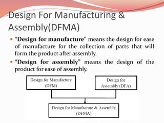
Presented by-
Sharath S
01JST16PAE013
Definition
 Concurrent engineering, also known as simultaneous
engineering, is a method of designing and developing
products, in which the different stages run
simultaneously, rather than consecutively.
 It decreases product development time and also the
time to market, leading to improved productivity and
reduced costs.
Why CE?
 Increasing product variety and technical complexity.
 Increasing global competitive pressure that results
from the emerging concept of reengineering.
 The need for rapid response to fast-changing
consumer demand.
 Large organizations with several departments working
on developing numerous products at the same time.
 New and innovative technologies emerging at a very
high rate.
Benefits of CE
 It encourages multidisciplinary collaboration
 It makes the design process faster
 It reduces costs and increases quality by supporting
the entire project life cycle
 It increases productivity by stopping mistakes in their
tracks
 It gives you a competitive advantage
Design For Manufacturing &
Assembly(DFMA)
 “Design for manufacture” means the design for ease
of manufacture for the collection of parts that will
form the product after assembly.
 “Design for assembly” means the design of the
product for ease of assembly.
Design for Manufacturing
 DFM is a set of methods and tools that support
concurrent engineering and that can be understood as
an analytical process structure of concurrent
engineering tools that provide conditions to design a
product regarding its manufacturability.
 Through the use of the DFM concepts, designers and
engineers can attain the main target: to satisfy the
customer’s requirements in terms of functionality,
performance, style and quality at low cost.
DFM benefits are:
 Simpler fabrication and assembly;
 Improved ergonomics;
 Reduced rework;
 Reduced mass;
 Improved serviceability;
 Better quality;
 Reduced logistic time;
 Reduced time to market launching;
 Less production problems;
 Reduced program budget.
Design for Assembly
 DFA is a DFM specialty; it is a structured method to
improve product components assembling.
DFA benefits are:
 Reduce and optimize part counts and types.
 Utilize optimum attachment methods.
 Use layered assembly approach. Let gravity help.
 Minimize reorientations during assembly.
 Eliminate the need for adjustments.
 Design parts so that they are easy to self-align and locate.
 Ensure ease and safety of part and assembly handling.
Design improvements by the DFA process
DFX – Design for X on the product
development
 Conceptual concurrent
engineering tools as DFR
(Design for Recycling), DFE
(Design for Environment) and
DFD (Design for Disassembly)
are contemplated in DFX
(Design for Excellence).
 The Design for X is a generic
term for all types of concurrent
engineering tools which are
oriented to consider
environment, recycling,
disassembly, life cycle, among
other requirements.
Design for Environment
 DFE considers all environment aspects in each phase
of the product development process. It is focused on
reducing as much as possible the environmental
impact of this product during its life cycle, since from
its manufacture just to its disposal
 Three main activities resulting from DFE
methodologies and that directly refer to product
valorisation at its life cycle end:
 Design for Disassembly – DFD;
 Design for Recyclability – DFR;
 Design for Remanufacturing – DFR.
DFM application to auto body
panels
 This case will be about the application of DFM in a specific
sheet metal part designed for product and manufacturing
engineering from a multinational automaker that has been
manufacturing stamped parts in Brazil for decades. Until
late 1980s, any size and type of metallic parts were
fabricated at the press shop of this company.
 One of the strategies adopted in the early 1990s was to be
focused only on the main stamped parts, like doors, side
panel, hood, fender, etc. Small parts and not “core
business”, small inner parts for instance, were outsourced.
 The main results were reduction of structural press shop
cost due to the disposal of smaller presses (“C” type and
progressive presses) and labour costs.
DFM Information Flow
Contd..
 Nowadays, the press shops only have a mechanical presses
line, each with its die stamping.
 The stamped sheet metal part manufacturability criteria
must be established before starting its design, because it
will be the standard and give support to design areas (see
the following maximum panel drawn in depth and blank
size criteria examples and a DFMA improvement of an
automotive door development). For these cases, the DFMA
methodology existed.
 The purpose of this analysis was to evaluate the blank
dimension and check if neither sheet metal part are over
estimated nor under estimated for the presses line.
If the panel depth is deeper than
the press size:
 Manufacturing costs
increase due to the need of
a double action press
resulting in a reduction of
throughput;
 Investment costs increase
due to the need of a panel
turnover;
 Part quality decreases and
manufacturing scrap
increase due to down dings
caused by dirt in the lower
die cavity.
If the panel size is larger than the
press size:
 Manufacturing costs increase due
to requiring a larger press size,
resulting in a reduction of
throughput.
 CAE (Computer Aided
Engineering) − useful to estimate
the sheet metal forming flow
blank size and blank nesting.
 Stamped part geometry and sheet
metal forming evolution;
 Width sheet metal distribution;
 Equivalent plastic forming;
 Material flow;
 Blank holder and female die
stamping force;
 Failure (tearing and wrinkle).
Summary
 In terms of the press shop facilities of the plant, the main results
were:
 Layout optimization;
 Press line automation feasibility;
 Reduced setup and increased productivity;
 Improved racks logistic;
 Reduced overhead;
 Reduced stamped part scraps;
 Resources with mechanical presses selling.
 In terms of the planning activities, the main results were:
 Reduce time to market;
 Reduce press shop machinery and die stamping investments;
 Reduce indirect cost.
CASE STUDY ON CONCURRENT ENGINEERING

CASE STUDY ON CONCURRENT ENGINEERING

  • 1.
  • 2.
    Definition  Concurrent engineering,also known as simultaneous engineering, is a method of designing and developing products, in which the different stages run simultaneously, rather than consecutively.  It decreases product development time and also the time to market, leading to improved productivity and reduced costs.
  • 3.
    Why CE?  Increasingproduct variety and technical complexity.  Increasing global competitive pressure that results from the emerging concept of reengineering.  The need for rapid response to fast-changing consumer demand.  Large organizations with several departments working on developing numerous products at the same time.  New and innovative technologies emerging at a very high rate.
  • 4.
    Benefits of CE It encourages multidisciplinary collaboration  It makes the design process faster  It reduces costs and increases quality by supporting the entire project life cycle  It increases productivity by stopping mistakes in their tracks  It gives you a competitive advantage
  • 5.
    Design For Manufacturing& Assembly(DFMA)  “Design for manufacture” means the design for ease of manufacture for the collection of parts that will form the product after assembly.  “Design for assembly” means the design of the product for ease of assembly.
  • 6.
    Design for Manufacturing DFM is a set of methods and tools that support concurrent engineering and that can be understood as an analytical process structure of concurrent engineering tools that provide conditions to design a product regarding its manufacturability.  Through the use of the DFM concepts, designers and engineers can attain the main target: to satisfy the customer’s requirements in terms of functionality, performance, style and quality at low cost.
  • 7.
    DFM benefits are: Simpler fabrication and assembly;  Improved ergonomics;  Reduced rework;  Reduced mass;  Improved serviceability;  Better quality;  Reduced logistic time;  Reduced time to market launching;  Less production problems;  Reduced program budget.
  • 8.
    Design for Assembly DFA is a DFM specialty; it is a structured method to improve product components assembling. DFA benefits are:  Reduce and optimize part counts and types.  Utilize optimum attachment methods.  Use layered assembly approach. Let gravity help.  Minimize reorientations during assembly.  Eliminate the need for adjustments.  Design parts so that they are easy to self-align and locate.  Ensure ease and safety of part and assembly handling.
  • 9.
    Design improvements bythe DFA process
  • 10.
    DFX – Designfor X on the product development  Conceptual concurrent engineering tools as DFR (Design for Recycling), DFE (Design for Environment) and DFD (Design for Disassembly) are contemplated in DFX (Design for Excellence).  The Design for X is a generic term for all types of concurrent engineering tools which are oriented to consider environment, recycling, disassembly, life cycle, among other requirements.
  • 11.
    Design for Environment DFE considers all environment aspects in each phase of the product development process. It is focused on reducing as much as possible the environmental impact of this product during its life cycle, since from its manufacture just to its disposal  Three main activities resulting from DFE methodologies and that directly refer to product valorisation at its life cycle end:  Design for Disassembly – DFD;  Design for Recyclability – DFR;  Design for Remanufacturing – DFR.
  • 12.
    DFM application toauto body panels  This case will be about the application of DFM in a specific sheet metal part designed for product and manufacturing engineering from a multinational automaker that has been manufacturing stamped parts in Brazil for decades. Until late 1980s, any size and type of metallic parts were fabricated at the press shop of this company.  One of the strategies adopted in the early 1990s was to be focused only on the main stamped parts, like doors, side panel, hood, fender, etc. Small parts and not “core business”, small inner parts for instance, were outsourced.  The main results were reduction of structural press shop cost due to the disposal of smaller presses (“C” type and progressive presses) and labour costs.
  • 13.
  • 14.
    Contd..  Nowadays, thepress shops only have a mechanical presses line, each with its die stamping.  The stamped sheet metal part manufacturability criteria must be established before starting its design, because it will be the standard and give support to design areas (see the following maximum panel drawn in depth and blank size criteria examples and a DFMA improvement of an automotive door development). For these cases, the DFMA methodology existed.  The purpose of this analysis was to evaluate the blank dimension and check if neither sheet metal part are over estimated nor under estimated for the presses line.
  • 15.
    If the paneldepth is deeper than the press size:  Manufacturing costs increase due to the need of a double action press resulting in a reduction of throughput;  Investment costs increase due to the need of a panel turnover;  Part quality decreases and manufacturing scrap increase due to down dings caused by dirt in the lower die cavity.
  • 16.
    If the panelsize is larger than the press size:  Manufacturing costs increase due to requiring a larger press size, resulting in a reduction of throughput.  CAE (Computer Aided Engineering) − useful to estimate the sheet metal forming flow blank size and blank nesting.  Stamped part geometry and sheet metal forming evolution;  Width sheet metal distribution;  Equivalent plastic forming;  Material flow;  Blank holder and female die stamping force;  Failure (tearing and wrinkle).
  • 17.
    Summary  In termsof the press shop facilities of the plant, the main results were:  Layout optimization;  Press line automation feasibility;  Reduced setup and increased productivity;  Improved racks logistic;  Reduced overhead;  Reduced stamped part scraps;  Resources with mechanical presses selling.  In terms of the planning activities, the main results were:  Reduce time to market;  Reduce press shop machinery and die stamping investments;  Reduce indirect cost.