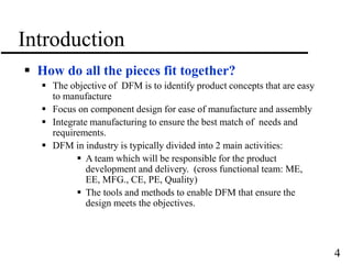
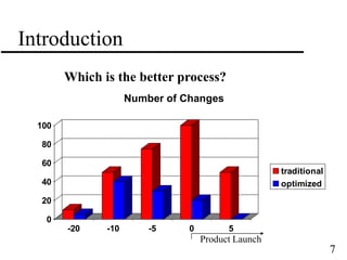
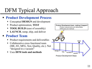
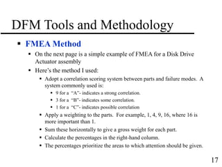
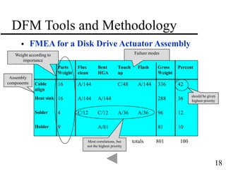
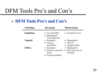
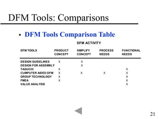
1
Design For Manufacturability
(DFM)
Steve Hanssen
Senior Engineer, Hitachi
San Jose State University
September 15, 2004
2
Agenda
Introduction
What is DFM? Why use DFM?
DFM Process
DFM Approach, DFM Tools and Methods
Summary
Overview and DFM comparison table
Where can I get more information?
Resources, DFM Pro’s and Con’s and Comparisons
3
Introduction
 What is DFM?
 DFM is product design considering manufacturing requirements
 DFM is the first step in which a team approach is taken to develop
the product
 DFM is an umbrella which covers a variety of tools and
techniques to accomplish a manufacturable product
 Why DFM?
 Lower development cost
 Shorter development time
 Faster manufacturing start of build
 Lower assembly and test costs
 Higher quality
4
Introduction
 How do all the pieces fit together?
 The objective of DFM is to identify product concepts that are easy
to manufacture
 Focus on component design for ease of manufacture and assembly
 Integrate manufacturing to ensure the best match of needs and
requirements.
 DFM in industry is typically divided into 2 main activities:
 A team which will be responsible for the product
development and delivery. (cross functional team: ME,
EE, MFG., CE, PE, Quality)
 The tools and methods to enable DFM that ensure the
design meets the objectives.
5
Introduction
How much do engineering changes cost after
the design has been launched?
0
1000
2000
3000
4000
5000
6000
7000
8000
9000
10000
Design Test Tool
Build
Prod
Cost
6
Introduction
When has the total cost be committed?
0
10
20
30
40
50
60
70
80
90
100
Design Testing Tool Build Production
Incurred
Commit
7
Introduction
Which is the better process?
0
20
40
60
80
100
-20 -10 -5 0 5
Number of Changes
traditional
optimized
Product Launch
8
Introduction
 Manufacturing Today
 Global Competition
 Trade barriers have been removed (NAFTA)
 Must compete with the best from all over the world
 Japan, Europe, India, Mexico, etc
 Infrastructure's forming off shore
 Quality Requirements
 ISO 9000
 Six Sigma (Motorola Inc)
 Product Cycles
 Every generation is faster
 Rate of change is increasing
 Cost
 Costs decrease every year (customers expect costs to go down)
 Performance increasing every year
9
Introduction: Global Manufacturing
Mfg: China
Mfg: China, Ireland
Mfg: Malaysia
Mfg: Thailand, Singapore, Hungary,
Philippines
Mfg: Japan, Thailand, Germany,
Philippines
Mfg: Mexico, China, Taiwan,
Philippines
Mfg: Singapore,
Thailand
Mfg: China, Ireland
10
Introduction: Product Design
 Product Design Today
 Development Cycle
 Endless engineering changes
 Non standard parts have long lead times
 Quality
 “Designed and thrown over the wall”
 Lower due to more parts, manual processes, and untested parts
 Customer configuration management
 Cost
 Higher due to unique designs and specialized parts
 Equipment and Tooling
 Reliability and quality problems
11
DFM Typical Approach
Design
Test Tool Build
Launch
finish
start
Product Development Steps
Product Development team making it happen!!
- Product requirements and deliverables
- DFM tools and methods
 Product Development Process
 Conceptual DESIGN and development
 Product optimization, TEST
 TOOL BUILD (ease of assembly)
 LAUNCH, ramp, ship, and deliver
 Product Team
 Product requirements and deliverables
 Collaborative cross functional team
(ME, EE, MFG, Test, Quality, etc.). Not
“designed in a vacuum”
 Uses DFM tools and methods
12
DFM Product Considerations
 Product Considerations
 Environmental
 Ergonomics
 Safety
 Pollution
 Recycling
 Shock/vibration
 Temperature
 Customer
 Depth of product line
 Customization
 Test requirements
 Process and Tooling
 Cycle time
 Quality
 Ease of Assembly
 Ease of Testing
 Rework
 Shipping and Handling
 Tooling Costs
 Suppliers
 Partnerships
 Supplier tolerance capability
 Merging mechanical sub-assemblies
 Costs
13
DFM Tools and Methodology
 Tools and Methodologies
 Design For Assembly (DFA), (IBM experience)
 Failure Mode and Effect Analysis (FMEA), (Sun example)
 Taguchi Method, (Hitachi experience)
 Value Analysis--”Value Engineering” (HP example)
 Quality Function Deployment (QFD), Going to the Gemba
(Hitachi)
 Group Technology, (IBM example)
 Cost management and optimization, SPC, Six-Sigma
(Motorola), TQC, etc
14
DFM Tools: DFA Guidelines
- Standard parts (one screw type)
- Parts are self-guiding
-Die cast with minimal amount of
holes (debris chip)
-Standard cutters
-Guide features
- Common datum’s for all fixtures
-One common plane for assembly
- Tabs for robotic lift
- One assembly direction “tops
down”
-No adjustments required
-No hidden features
- bottom rails for conveyor
- Test direction access from top
- Easy to fabricate parts
- Sub-assemblies reduce
handling of small hard to grip
parts - Symmetry in two axis
- Holes large enough
(straightness issues if too deep)
- Avoid tangle with use of
fixtures
15
DFM Tools: DFA Guidelines
 Summary of DFA Guidelines
1. Minimize the number of parts
2. Standardize and use as many common parts as possible
3. Design parts for ease of fabrication (use castings without machining and
stampings without bend)
4. Minimize the number of assembly planes (Z-axis)
5. Use standard cutters, drills, tools
6. Avoid small holes (chips, straightness, debris)
7. Use common datum’s for tooling fixtures
8. Minimize assembly directions
9. Maximize compliance; design for assembly
10. Minimize handling
11. Eliminate adjustments
12. Use repeatable, well understood processes
13. Design parts for efficient testing
14. Avoid hidden features
15. Use Guide features
16. Incorporate symmetry in both axis
17. Avoid designs that will tangle.
18. Design parts that orient themselves
16
DFM Tools and Methodology
 FMEA (Failure Mode and Effects Analysis)
 Method for analyzing the causes and effects of failures.
 Highlights designs and assemblies most likely to cause failures.
 Helps identify and prioritize corrective action
 Indicates where the most improvement in terms of severity,
frequency, and detectability can be made.
 Widely used manufacturing technique (Mil standards, SAE, ANSI
Specs)
17
DFM Tools and Methodology
 FMEA Method
 On the next page is a simple example of FMEA for a Disk Drive
Actuator assembly
 Here’s the method I used:
 Adopt a correlation scoring system between parts and failure modes. A
system commonly used is:
 9 for a “A”- indicates a strong correlation.
 3 for a “B”- indicates some correlation.
 1 for a “C”- indicates possible correlation
 Apply a weighting to the parts. For example, 1, 4, 9, 16, where 16 is
more important than 1.
 Sum these horizontally to give a gross weight for each part.
 Calculate the percentages in the right-hand column.
 The percentages prioritize the areas to which attention should be given.
18
DFM Tools and Methodology
 FMEA for a Disk Drive Actuator Assembly
Parts
Weight
Flux
clean
Bent
HGA
Touch
up
Flash Gross
Weight
Percent
Cable
align
16 A/144 C/48 A/144 336 42
Heat sink 16 A/144 A/144 288 36
Solder 4 C/12 C/12 A/36 A/36 96 12
Holder 9 A/81 81 10
totals 801 100
should be given
highest priority
Most correlations, but
not the highest priority
Assembly
components
Weight according to
importance
Failure modes
19
Summary
 What is DFM?
 Design considering manufacturing
 Why DFM?
 Shorter Development Cycle
 Lower costs and higher quality
 Fewer Engineering Changes
 DFM Approach
 “Integrated” in product design process.
 Not “designed in a vacuum”
 Tools and Methods
 Design is the first manufacturing step.
 The essence is use a combination of tools and methods which are
appropriate for your application
20
DFM Tools Pro’s and Con’s
 DFM Tools Pro’s and Con’s
Technique Advantage Disadvantage
Guidelines  Cost and Effort
 Management
Team Approach
 Exceptions to list
Taguchi  Systematic
 Narrows
possibilities
 Management
 “Buy-in”
 Designer Effort
FMEA  Systematic
 Priortizte corrective
action
 Provides guidance
 Management
 Rates only ease of
assembly
21
DFM Tools: Comparisons
 DFM Tools Comparison Table
DFM ACTIVITY
DFM TOOLS PRODUCT SIMPLIFY PROCESS FUNCTIONAL
CONCEPT CONCEPT NEEDS NEEDS
DESIGN GUIDELINES X X
DESIGN FOR ASSEMBLY X
TAGUCHI X X
CUMPUTER AIDED DFM X X X X
GROUP TECHNOLOGY X X
FMEA X X
VALUE ANALYSIS X
22
References
 A Few DFM References
 Baer, T., “With Group Technology Nobody Reinvents the Wheel.” Mechanical Engineering, November 1995.
 Boothroyd, et al., “Computer Aided Design for Assembly.” Assembly Engineering, February, 1993.
 Boothroyd, et al., “Design for Assembly: Selecting the Right Method.”, Machine Design, December, 1983.
 Boothroyd, G. “Make it Simple Design for Assembly.” Mechanical Engineering, February 1988.
 Gage, W.L., “Value Analysis, McGraw-Hill, Inc, New York, 1967.
 Owen,T., “Assembly With Robots.” Prentice-Hall, Inc., Englewood NJ, 1985
 Burgam, P.M.,Design of Experiments-The Taguchi Way.” Manufacturing Engineering, May, 1985
 Evens, B., “Simultaneous Engineering.” Mechanical Engineering, February 1985.
 Stoll, H.W., “Design for Manufacture.” Manufacturing Engineering, January 1988.
 Boothroyd, G., “Design for Assembly.” Mechanical Engineering, February 1988.
 Barkan, P., “The Benefits and Limitations of Structured Design Methodologies.” ASME, Manufacturing Review,
vol. 6, no. 3, September 1993.
 Baralla, J.G., “Handbook of Product Design for Manufacturing.” McGraw-Hill, 1988.
 Harry, M.J., “The Nature of Six Sigma Quality.” Motorola, Inc., Government Electronics Group.
 Donnelly, T.A., “Robust Product Design.” Machine Design, October 8, 1988.
 Sadri,H, et al., “Design of Experiments: An Invaluable.” Production Engineering, February 1994.
 Box G., et al., “Statistical Tools for Improving Designs.” Mechanical Engineering, January 1988.
 Miles, L.D., “Techniques of Value Analysis and Engineering, McGraw Hill, NY, 2nd ed., 1972.
23
I Want to Learn More!
 Where else?
 SCPD.stanford.edu, ME396 (DFM Forum)
 CACT Center, De Anza College, DFM Seminar
 University of Rode Island, DFA

DFMHanssen15SEP04.ppt

  • 1.
    1 Design For Manufacturability (DFM) SteveHanssen Senior Engineer, Hitachi San Jose State University September 15, 2004
  • 2.
    2 Agenda Introduction What is DFM?Why use DFM? DFM Process DFM Approach, DFM Tools and Methods Summary Overview and DFM comparison table Where can I get more information? Resources, DFM Pro’s and Con’s and Comparisons
  • 3.
    3 Introduction  What isDFM?  DFM is product design considering manufacturing requirements  DFM is the first step in which a team approach is taken to develop the product  DFM is an umbrella which covers a variety of tools and techniques to accomplish a manufacturable product  Why DFM?  Lower development cost  Shorter development time  Faster manufacturing start of build  Lower assembly and test costs  Higher quality
  • 4.
    4 Introduction  How doall the pieces fit together?  The objective of DFM is to identify product concepts that are easy to manufacture  Focus on component design for ease of manufacture and assembly  Integrate manufacturing to ensure the best match of needs and requirements.  DFM in industry is typically divided into 2 main activities:  A team which will be responsible for the product development and delivery. (cross functional team: ME, EE, MFG., CE, PE, Quality)  The tools and methods to enable DFM that ensure the design meets the objectives.
  • 5.
    5 Introduction How much doengineering changes cost after the design has been launched? 0 1000 2000 3000 4000 5000 6000 7000 8000 9000 10000 Design Test Tool Build Prod Cost
  • 6.
    6 Introduction When has thetotal cost be committed? 0 10 20 30 40 50 60 70 80 90 100 Design Testing Tool Build Production Incurred Commit
  • 7.
    7 Introduction Which is thebetter process? 0 20 40 60 80 100 -20 -10 -5 0 5 Number of Changes traditional optimized Product Launch
  • 8.
    8 Introduction  Manufacturing Today Global Competition  Trade barriers have been removed (NAFTA)  Must compete with the best from all over the world  Japan, Europe, India, Mexico, etc  Infrastructure's forming off shore  Quality Requirements  ISO 9000  Six Sigma (Motorola Inc)  Product Cycles  Every generation is faster  Rate of change is increasing  Cost  Costs decrease every year (customers expect costs to go down)  Performance increasing every year
  • 9.
    9 Introduction: Global Manufacturing Mfg:China Mfg: China, Ireland Mfg: Malaysia Mfg: Thailand, Singapore, Hungary, Philippines Mfg: Japan, Thailand, Germany, Philippines Mfg: Mexico, China, Taiwan, Philippines Mfg: Singapore, Thailand Mfg: China, Ireland
  • 10.
    10 Introduction: Product Design Product Design Today  Development Cycle  Endless engineering changes  Non standard parts have long lead times  Quality  “Designed and thrown over the wall”  Lower due to more parts, manual processes, and untested parts  Customer configuration management  Cost  Higher due to unique designs and specialized parts  Equipment and Tooling  Reliability and quality problems
  • 11.
    11 DFM Typical Approach Design TestTool Build Launch finish start Product Development Steps Product Development team making it happen!! - Product requirements and deliverables - DFM tools and methods  Product Development Process  Conceptual DESIGN and development  Product optimization, TEST  TOOL BUILD (ease of assembly)  LAUNCH, ramp, ship, and deliver  Product Team  Product requirements and deliverables  Collaborative cross functional team (ME, EE, MFG, Test, Quality, etc.). Not “designed in a vacuum”  Uses DFM tools and methods
  • 12.
    12 DFM Product Considerations Product Considerations  Environmental  Ergonomics  Safety  Pollution  Recycling  Shock/vibration  Temperature  Customer  Depth of product line  Customization  Test requirements  Process and Tooling  Cycle time  Quality  Ease of Assembly  Ease of Testing  Rework  Shipping and Handling  Tooling Costs  Suppliers  Partnerships  Supplier tolerance capability  Merging mechanical sub-assemblies  Costs
  • 13.
    13 DFM Tools andMethodology  Tools and Methodologies  Design For Assembly (DFA), (IBM experience)  Failure Mode and Effect Analysis (FMEA), (Sun example)  Taguchi Method, (Hitachi experience)  Value Analysis--”Value Engineering” (HP example)  Quality Function Deployment (QFD), Going to the Gemba (Hitachi)  Group Technology, (IBM example)  Cost management and optimization, SPC, Six-Sigma (Motorola), TQC, etc
  • 14.
    14 DFM Tools: DFAGuidelines - Standard parts (one screw type) - Parts are self-guiding -Die cast with minimal amount of holes (debris chip) -Standard cutters -Guide features - Common datum’s for all fixtures -One common plane for assembly - Tabs for robotic lift - One assembly direction “tops down” -No adjustments required -No hidden features - bottom rails for conveyor - Test direction access from top - Easy to fabricate parts - Sub-assemblies reduce handling of small hard to grip parts - Symmetry in two axis - Holes large enough (straightness issues if too deep) - Avoid tangle with use of fixtures
  • 15.
    15 DFM Tools: DFAGuidelines  Summary of DFA Guidelines 1. Minimize the number of parts 2. Standardize and use as many common parts as possible 3. Design parts for ease of fabrication (use castings without machining and stampings without bend) 4. Minimize the number of assembly planes (Z-axis) 5. Use standard cutters, drills, tools 6. Avoid small holes (chips, straightness, debris) 7. Use common datum’s for tooling fixtures 8. Minimize assembly directions 9. Maximize compliance; design for assembly 10. Minimize handling 11. Eliminate adjustments 12. Use repeatable, well understood processes 13. Design parts for efficient testing 14. Avoid hidden features 15. Use Guide features 16. Incorporate symmetry in both axis 17. Avoid designs that will tangle. 18. Design parts that orient themselves
  • 16.
    16 DFM Tools andMethodology  FMEA (Failure Mode and Effects Analysis)  Method for analyzing the causes and effects of failures.  Highlights designs and assemblies most likely to cause failures.  Helps identify and prioritize corrective action  Indicates where the most improvement in terms of severity, frequency, and detectability can be made.  Widely used manufacturing technique (Mil standards, SAE, ANSI Specs)
  • 17.
    17 DFM Tools andMethodology  FMEA Method  On the next page is a simple example of FMEA for a Disk Drive Actuator assembly  Here’s the method I used:  Adopt a correlation scoring system between parts and failure modes. A system commonly used is:  9 for a “A”- indicates a strong correlation.  3 for a “B”- indicates some correlation.  1 for a “C”- indicates possible correlation  Apply a weighting to the parts. For example, 1, 4, 9, 16, where 16 is more important than 1.  Sum these horizontally to give a gross weight for each part.  Calculate the percentages in the right-hand column.  The percentages prioritize the areas to which attention should be given.
  • 18.
    18 DFM Tools andMethodology  FMEA for a Disk Drive Actuator Assembly Parts Weight Flux clean Bent HGA Touch up Flash Gross Weight Percent Cable align 16 A/144 C/48 A/144 336 42 Heat sink 16 A/144 A/144 288 36 Solder 4 C/12 C/12 A/36 A/36 96 12 Holder 9 A/81 81 10 totals 801 100 should be given highest priority Most correlations, but not the highest priority Assembly components Weight according to importance Failure modes
  • 19.
    19 Summary  What isDFM?  Design considering manufacturing  Why DFM?  Shorter Development Cycle  Lower costs and higher quality  Fewer Engineering Changes  DFM Approach  “Integrated” in product design process.  Not “designed in a vacuum”  Tools and Methods  Design is the first manufacturing step.  The essence is use a combination of tools and methods which are appropriate for your application
  • 20.
    20 DFM Tools Pro’sand Con’s  DFM Tools Pro’s and Con’s Technique Advantage Disadvantage Guidelines  Cost and Effort  Management Team Approach  Exceptions to list Taguchi  Systematic  Narrows possibilities  Management  “Buy-in”  Designer Effort FMEA  Systematic  Priortizte corrective action  Provides guidance  Management  Rates only ease of assembly
  • 21.
    21 DFM Tools: Comparisons DFM Tools Comparison Table DFM ACTIVITY DFM TOOLS PRODUCT SIMPLIFY PROCESS FUNCTIONAL CONCEPT CONCEPT NEEDS NEEDS DESIGN GUIDELINES X X DESIGN FOR ASSEMBLY X TAGUCHI X X CUMPUTER AIDED DFM X X X X GROUP TECHNOLOGY X X FMEA X X VALUE ANALYSIS X
  • 22.
    22 References  A FewDFM References  Baer, T., “With Group Technology Nobody Reinvents the Wheel.” Mechanical Engineering, November 1995.  Boothroyd, et al., “Computer Aided Design for Assembly.” Assembly Engineering, February, 1993.  Boothroyd, et al., “Design for Assembly: Selecting the Right Method.”, Machine Design, December, 1983.  Boothroyd, G. “Make it Simple Design for Assembly.” Mechanical Engineering, February 1988.  Gage, W.L., “Value Analysis, McGraw-Hill, Inc, New York, 1967.  Owen,T., “Assembly With Robots.” Prentice-Hall, Inc., Englewood NJ, 1985  Burgam, P.M.,Design of Experiments-The Taguchi Way.” Manufacturing Engineering, May, 1985  Evens, B., “Simultaneous Engineering.” Mechanical Engineering, February 1985.  Stoll, H.W., “Design for Manufacture.” Manufacturing Engineering, January 1988.  Boothroyd, G., “Design for Assembly.” Mechanical Engineering, February 1988.  Barkan, P., “The Benefits and Limitations of Structured Design Methodologies.” ASME, Manufacturing Review, vol. 6, no. 3, September 1993.  Baralla, J.G., “Handbook of Product Design for Manufacturing.” McGraw-Hill, 1988.  Harry, M.J., “The Nature of Six Sigma Quality.” Motorola, Inc., Government Electronics Group.  Donnelly, T.A., “Robust Product Design.” Machine Design, October 8, 1988.  Sadri,H, et al., “Design of Experiments: An Invaluable.” Production Engineering, February 1994.  Box G., et al., “Statistical Tools for Improving Designs.” Mechanical Engineering, January 1988.  Miles, L.D., “Techniques of Value Analysis and Engineering, McGraw Hill, NY, 2nd ed., 1972.
  • 23.
    23 I Want toLearn More!  Where else?  SCPD.stanford.edu, ME396 (DFM Forum)  CACT Center, De Anza College, DFM Seminar  University of Rode Island, DFA