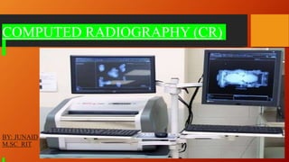
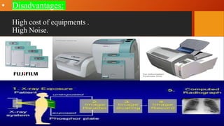
COMPUTED RADIOGRAPHY (CR)
BY: JUNAID
M.SC RIT
•
COMPUTED RADIOGRAPHY (CR)
Definition:
It is a process of capturing radiographic data from a conventional X-
ray machine and processing the data digitally to produce crisp (hard
and dry) and high quality radiographic images.
OR
It is a commonly used system of digital radiographic imaging that use
PSP ( Photostimulable Phosphor ) plate to capture radiographic data
from high quality radiographic images.
 It is considered as a bridge between classical radiography
increasingly popular fully digital method.
CR is a digital replacement of conventional X-ray film radiography.
HISTORY:
In 1973 George Lucky a research scientist at Eastman Kodak
Company filled patent application title “Apparatus and method for
producing image corresponding to pattern of high energy radiation.
1975 when George’s patent was approved at the same time kodak also
patented the first scanned storage phosphor system.
1983 Fuji was the first to commericiable a complete CR System.
Principle of Computed Radiography (CR) :
Computed Radiography is based on PSL (Photostimulable Luminescene)
principle.
PSL is a release of stored energy within phosphor by stimulation with visible
light to produce luminescent signals.
Step-1 : Phosphor layer absorb X-ray photons and stores its energy in the form of
trapped electron (Latent Image).
Step 2 : Latent image is then scanned by the reader with the help of Red Laser
light .
The amount of luminescene produced is proportional to radiation received.
Equipments of CR system :
1. Imaging Plate
2. Imaging Plate Reader.
3. Imaging Display System.
4. Imaging Storage System.
5. Image Management System.
6. A Communication Network.
1. Imaging Plate: Captures images in thin sheets.
Construction of IP:
IP mainly consists of 5 Layers viz:
(i) Protective layer ( plastic or
corbon fibre )
(ii) Phosphor layer (BaFu 85% /BrI 15%
doping with Eu)
Eu acts as an Activator
(iii) Reflective layer
(iv) Conductive layer
(v) Supportive layer (polyster)
Reflective layer:
This is the layer that sends lights in a forward direction when released in
cassette reader.
Conductive layer:
This is a layer of material that absorbs and reduces static electricity.
Base :
It improves support to the other layer.
2. Imaging Plate Reader :
After the radiation exposure the CR cassette is inserted into the reader where the
imaging plate is removed and fitted into drive mechanism.
3. Image Display System :
ADC (Analog to digital conversion) converts electric signal to digital
signal which will be displayed on computer.
4. Imaging Storage System:
After display of image, image can be printed or stored.
STEPS IN THE CR
Exposure
• Phosphor exposed to X-
ray photon
• Eu²⁺ + X-ray = Eu³⁺ e
Reader
• PSP is scanned with Red
laser light to stimulate the
trapped e in the screen.
(Helium Neon Laiser
• Wave length 633nm
Erase
• The phosphor will not give up
all its trapped e after scanning
with Red laser light.
• These es moves to
valance bandto
conduction band , later
they are trapped at the
F-centre.
• The es absorb energy and
reach to the conduction band
where they become mobile
again and moves to valance
band with emission of Blue-
green light .Thees joins with
Eu³⁺ and converts into Eu²⁺.
• Eu³⁺ + e = Eu²⁺
• It will retain some amount of
trapped e. Hence it is to be
exposed to a very bright white
light which moves all the
trapped e to valance band ,
thus emerging the F-centre.
• No. of es per unit area is
proportional to the absorbed
radiation energy.
• PMT is used to collect this light
and gives on electrical signal.
• Now PSP can be re-
used for the another
exposure.
• In the time the es may return
to the ground state at their
own.
Electron signal digitalised by using
ABC and stored in memory.
 Advantages of CR System:
Computed Radiography is the digital replacement of conventional X-ray film
radiography and offers enormous advantages for the inspection time period.
1.Short time period
2.Imaging plates are re-usable,
3.No dark room or chemical required.
4.Reduction in exposure and processing.
5.Software based evaluation and imaging.
6. Less radiation dose to the patient.
7.Low per image cost.
8.Image can be stored.
9.Image can be modified with good contrast.
10. Very clear images for the diagnostic evaluation.
• Disadvantages:
High cost of equipments .
High Noise.

CR (Computed Radiography) System

  • 1.
  • 2.
    • COMPUTED RADIOGRAPHY (CR) Definition: Itis a process of capturing radiographic data from a conventional X- ray machine and processing the data digitally to produce crisp (hard and dry) and high quality radiographic images. OR It is a commonly used system of digital radiographic imaging that use PSP ( Photostimulable Phosphor ) plate to capture radiographic data from high quality radiographic images.
  • 3.
     It isconsidered as a bridge between classical radiography increasingly popular fully digital method. CR is a digital replacement of conventional X-ray film radiography. HISTORY: In 1973 George Lucky a research scientist at Eastman Kodak Company filled patent application title “Apparatus and method for producing image corresponding to pattern of high energy radiation. 1975 when George’s patent was approved at the same time kodak also patented the first scanned storage phosphor system. 1983 Fuji was the first to commericiable a complete CR System.
  • 4.
    Principle of ComputedRadiography (CR) : Computed Radiography is based on PSL (Photostimulable Luminescene) principle. PSL is a release of stored energy within phosphor by stimulation with visible light to produce luminescent signals. Step-1 : Phosphor layer absorb X-ray photons and stores its energy in the form of trapped electron (Latent Image). Step 2 : Latent image is then scanned by the reader with the help of Red Laser light . The amount of luminescene produced is proportional to radiation received.
  • 5.
    Equipments of CRsystem : 1. Imaging Plate 2. Imaging Plate Reader. 3. Imaging Display System. 4. Imaging Storage System. 5. Image Management System. 6. A Communication Network.
  • 6.
    1. Imaging Plate:Captures images in thin sheets. Construction of IP: IP mainly consists of 5 Layers viz: (i) Protective layer ( plastic or corbon fibre ) (ii) Phosphor layer (BaFu 85% /BrI 15% doping with Eu) Eu acts as an Activator (iii) Reflective layer (iv) Conductive layer (v) Supportive layer (polyster)
  • 7.
    Reflective layer: This isthe layer that sends lights in a forward direction when released in cassette reader. Conductive layer: This is a layer of material that absorbs and reduces static electricity. Base : It improves support to the other layer.
  • 8.
    2. Imaging PlateReader : After the radiation exposure the CR cassette is inserted into the reader where the imaging plate is removed and fitted into drive mechanism. 3. Image Display System : ADC (Analog to digital conversion) converts electric signal to digital signal which will be displayed on computer. 4. Imaging Storage System: After display of image, image can be printed or stored.
  • 9.
    STEPS IN THECR Exposure • Phosphor exposed to X- ray photon • Eu²⁺ + X-ray = Eu³⁺ e Reader • PSP is scanned with Red laser light to stimulate the trapped e in the screen. (Helium Neon Laiser • Wave length 633nm Erase • The phosphor will not give up all its trapped e after scanning with Red laser light. • These es moves to valance bandto conduction band , later they are trapped at the F-centre. • The es absorb energy and reach to the conduction band where they become mobile again and moves to valance band with emission of Blue- green light .Thees joins with Eu³⁺ and converts into Eu²⁺. • Eu³⁺ + e = Eu²⁺ • It will retain some amount of trapped e. Hence it is to be exposed to a very bright white light which moves all the trapped e to valance band , thus emerging the F-centre.
  • 10.
    • No. ofes per unit area is proportional to the absorbed radiation energy. • PMT is used to collect this light and gives on electrical signal. • Now PSP can be re- used for the another exposure. • In the time the es may return to the ground state at their own. Electron signal digitalised by using ABC and stored in memory.
  • 11.
     Advantages ofCR System: Computed Radiography is the digital replacement of conventional X-ray film radiography and offers enormous advantages for the inspection time period. 1.Short time period 2.Imaging plates are re-usable, 3.No dark room or chemical required. 4.Reduction in exposure and processing. 5.Software based evaluation and imaging. 6. Less radiation dose to the patient. 7.Low per image cost. 8.Image can be stored. 9.Image can be modified with good contrast. 10. Very clear images for the diagnostic evaluation.
  • 12.
    • Disadvantages: High costof equipments . High Noise.