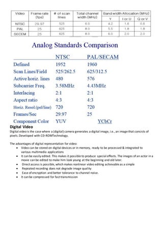
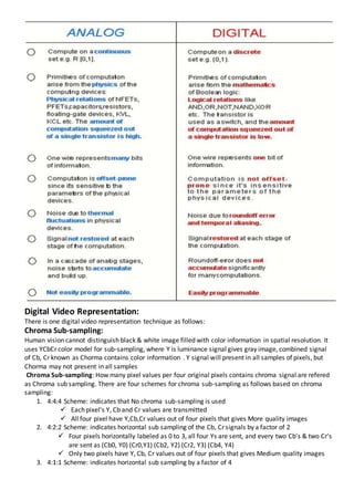
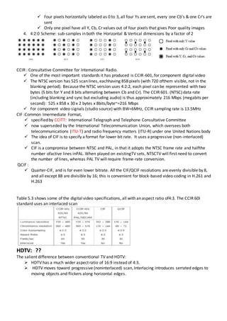
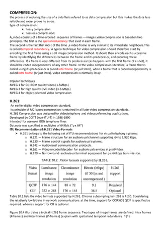
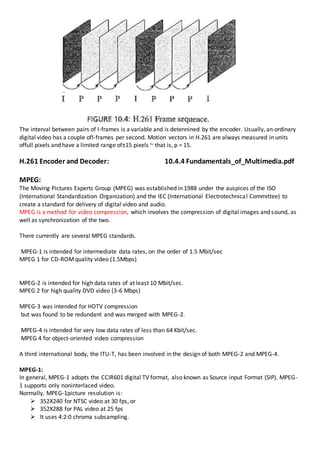
Types of Video Signals
Analog Video:
An analog video camera converts the image it “sees” through its lens to an electric voltage (a signal) that
varies with time according to the intensity and color of the light emitted from the different image parts.
Such a signal is called analog, because it is analogous (proportional) to the light intensity.
An analog signal f(t) samples a time-varying image signal, Progressive scanning traces through a complete
picture (a frame) row-wise for each time interval.
In TV and in some monitors and multimedia standards, anothersystem, interlaced scanning, is used. Here,
the odd-numbered lines are traced first, then the even-numbered lines.
Solid lines traced from P to Q is known as Odd field, Similarly Doted line traces in the frame is known as
Even field . Odd and Even fields - two fields make up one Frame.
Odd lines starts at top left corner of Frame (P) & ends at bottom center point (T), similarly Even lines starts
at center point of Frame (U) & ends at lower right corner point (V).
First solid (Odd) lines are traced, then Even field starts at U and ends at V. Jump from Q to R is called
Horizontal retrace, during which electronic beam in CRT is Blanked. Jump from T to U is called Vertical
retrace, during which electronic beam generate Sync signal.
In general, electron beam will generate Sync. signal for Horizontal retrace in 0.9 µs. Later Active scan line
signal is generated in 52.7 µs. Different voltages are used to refer different type of signals:
 Blank signal with 0 Volts
 Sync. Signal with -0.286 Volts
 White color with 0.714 Volts
 Black color with 0.055 Volts
Analog Video Representations:
There are three analog video representation techniques as follows:
1) NTSC Video:
NTSC (National Television System Committee) TV standard is mostly used in North America and Japan.
It uses the familiar 4:3 aspect ratio (i.e., the ratio of picture width to its height)
Uses 525 scan lines per frame at 30 frames per second (fps).
NTSC follows interlaced scanning system
NTSC uses YIQ color model.
Color sub carrier frequency is Fsc=3.58MHz.
It uses quadrate modulation to combine I & Q signals into single chroma signal
NTSC uses band width of 6.0 MHz, in which various sub carriers used frequencies as follows:
 Picture Carrier is at 1.25 MHz
 Audio Sub Carrier frequency is 4.5 MHz
2) PAL Video:
PAL (Phase Altering Line) TV standard originally invented by germen scientist.
It uses 625 scan lines per frame at 25 fps with 4:3 aspect ratio,
PAL uses YUV color model with 8 MHz channel, allocating band width of 5.5 MHz to Y and 1.8 MHz to each
U & V.
Color sub carrier frequency is Fsc=4.43MHz.
Chroma signals have altering signs as +U & -U in successive scan lines hence the name Phase Altering Line.
The signals in consecutive lines are averaged so as to cancel chroma signal for separating Y and C. It uses
Comb filter at receiver
3) SECAM Video:
SECAM (Systeme Electronique Couleur Avec Memoire) is invented by French for TV broadcast.
It uses 625 scan lines per frame at 25 fps with 4:3 aspect ratio & interlaced fields.
SECAM and PAL are similar, differing slightly in their color coding scheme.
In SECAM, U & V signals are modulated using separate color sub carriers at 4.25 MHz and 4.41 MHz.
They are sent in alternate lines that is, only one of U or V signals will be sent on each scan line
Digital Video
Digital video is the case where a (digital) camera generates a digital image, i.e., an image that consists of
pixels.Developed with CD-ROMTechnology.
The advantages of digital representation for video:
 Video can be stored on digital devices or in memory, ready to be processed & integrated to
various multimedia applications
 It can be easily edited. This makes it possible to produce special effects. The images of an actor in a
movie can be edited to make him look young at the beginning and old later.
 Direct access is possible, which makes nonlinear video editing achievable as a simple
 Repeated recording does not degrade image quality
 Ease of encryption and better tolerance to channel noise.
 It can be compressed for fast transmission
Digital Video Representation:
There is one digital video representation technique as follows:
Chroma Sub-sampling:
Human vision cannot distinguish black & white image filled with color information in spatial resolution. It
uses YCbCr color model for sub-sampling, where Y is luminance signal gives gray image, combined signal
of Cb, Cr known as Chorma contains color information . Y signal will present in all samples of pixels, but
Chorma may not present in all samples
Chroma Sub-sampling: How many pixel values per four original pixels contains chroma signal are refered
as Chroma sub sampling. There are four schemes for chroma sub-sampling as follows based on chroma
sampling:
1. 4:4:4 Scheme: indicates that No chroma sub-sampling is used
 Each pixel's Y, Cb and Cr values are transmitted
 All four pixel have Y,Cb,Cr values out of four pixels that gives More quality images
2. 4:2:2 Scheme: indicates horizontal sub sampling of the Cb, Cr signals by a factor of 2
 Four pixels horizontally labeled as 0 to 3, all four Ys are sent, and every two Cb's & two Cr's
are sent as (Cb0, Y0) (Cr0,Y1) (Cb2, Y2) (Cr2, Y3) (Cb4, Y4)
 Only two pixels have Y, Cb, Cr values out of four pixels that gives Medium quality images
3. 4:1:1 Scheme: indicates horizontal sub sampling by a factor of 4
 Four pixels horizontally labeled as 0 to 3, all four Ys are sent, every one Cb's & one Cr's are
sent
 Only one pixel have all Y, Cb, Cr values out of four pixels that gives Poor quality images
4. 4:2:0 Scheme: sub-samples in both the Horizontal & Vertical dimensions by a factor of 2
CCIR : Consultative Committee for Intemational Radio.
 One of the most important standards it has produced is CCIR-601, for component digital video
 The NTSC version has 525 scan lines, eachhaving 858 pixels (with 720 ofthem visible, not in the
blanking period). Because the NTSC version uses 4:2:2, each pixel can be represented with two
bytes (S bits for Y and 8 bits alternating between Cb and Cr). The CCIR 601. (NTSC) data rate
(including blanking and sync but excluding audio) is thus approximately 216 Mbps (megabits per
second): 525 x 858 x 30 x 2 bytes x 8bits/byte~=216 Mbps
 For component video signals (studio source) with BW=6MHz, CCIR sampling rate is 13.5MHz
CIF :Common Imermediate Format,
 specified by CCITT: International Telegraph and Telephone Consultative Committee
 now superseded by the International Telecommunication Union, which oversees both
telecommunications (ITU-T) and radio frequency matters (ITU-R) under one United Nations body
 The idea of CIF is to specify a format for lower bit rate. It uses a progressive (non-interlaced)
scan.
 CIF is a compromise between NTSC and PAL, in that it adopts the NTSC frame rate and halfthe
number ofactive lines inPAL. When played on existingTV sets, NTSCTV will first need to convert
the number of lines, whereas PAL TV will require frame-rate conversion.
QCIF :
 Quarter-CIF, and is for even lower bitrate. All the CIF/QCIF resolutions are evenly divisible by 8,
and all except 88 are divisible by 16; this is convenient for block-based video coding in H.261 and
H.263
Table 5.3 shows some of the digital video specifications, all with an aspect ratio of4:3. The CCIR 60I
standard uses an interlaced scan
HDTV: ??
The salient difference between conventional TV and HDTV:
 HDTV has a much wider aspect ratio of 16:9 instead of 4:3.
 HDTV moves toward progressive (noninterlaced) scan, Interlacing introduces serrated edges to
moving objects and flickers along horizontal edges.
COMPRESSION:
the process of reducing the size of a datafile is refered to as data compression but this makes the data less
reliable and more prome to errors.
type of compression :
 lossy compression:
 lossless compression:
A_video.consists of a time-ordered sequence of frames ---images.video compression is based on two
principles.The first is the spatial redundancy that exist in each frame.
The second is the fact that most of the time ,a video frame is very similar to its immediate neighbours.This
is called temporal redundency. A typical technique for video compression should therefore start by
encoding the first frame using a still image compression method. It should then encode each successive
frame by identifying the differences between the frame and its predecessor, and encoding these
differences. If a frame is very different from its predecessor (as happens with the first frame of a shot), it
should be coded independently of any other frame. In the video compression literature, a frame that is
coded using its predecessor is called inter frame (or just inter), while a frame that is coded independently is
called intra frame (or just intra). Video compression is normally lossy.
Popular techniques
MPEG 1 for CD-ROMquality video (1.5Mbps)
MPEG 2 for high quality DVD video (3-6 Mbps)
MPEG 4 for object-oriented video compression
H.261:
An earlier digital video compression standard,
its principle of MC-based compression is retained in all later video compression standards.
H. 261 Compression was designed for videotelephony and videoconferencing applications.
Developed by CCITT (now ITU-T) in 1988-1990
Intended for use over ISDN telephone lines
Datarate was specified as multiples of 64Kb/s (“p x 64”)
ITU Recommendations & H.261 Video Formats
 H.261 belongs to the following set of ITU recommendations for visual telephony systems:
o H.221 — Frame structure for an audiovisual channel supporting 64 to 1,920 kbps.
o H.230 — Frame control signals for audiovisual systems.
o H.242 — Audiovisual communication protocols.
o H.261 — Video encoder/decoder for audiovisual services at p x 64 kbps.
o H.320 — Narrow-band audiovisual terminal equipment for p x 64 kbps transmission.
Table 10.2 lists the video formats supported by H.261. Chroma subsampling in H.261 is 4:2:0. Considering
the relatively low bitrate in network communications at the time, support for CCIR 601 QCIF is specified as
required, whereas support for ClF is optional.
Figure 10.4 illustrates a typical H.261 frame sequence. Two types of image frames are defined: intra frames
(I-frames) and inter-frames (P-frames).(explain with spatial and temporal redundency ^|^)
The interval between pairs of I-frames is a variable and is detennined by the encoder. Usually, an ordinary
digital video has a couple ofI-frames per second. Motion vectors in H.261 are always measured in units
offull pixels and have a limited range of±15 pixels ~ that is, p = 15.
H.261 Encoder and Decoder: 10.4.4 Fundamentals_of_Multimedia.pdf
MPEG:
The Moving Pictures Experts Group (MPEG) was established in 1988 under the auspices of the ISO
(International Standardization Organization) and the IEC (International Electrotechnical Committee) to
create a standard for delivery of digital video and audio.
MPEG is a method for video compression, which involves the compression of digital images and sound, as
well as synchronization of the two.
There currently are several MPEG standards.
MPEG-1 is intended for intermediate data rates, on the order of 1.5 Mbit/sec
MPEG 1 for CD-ROMquality video (1.5Mbps)
MPEG-2 is intended for high data rates of at least 10 Mbit/sec.
MPEG 2 for high quality DVD video (3-6 Mbps)
MPEG-3 was intended for HDTV compression
but was found to be redundant and was merged with MPEG-2.
MPEG-4 is intended for very low data rates of less than 64 Kbit/sec.
MPEG 4 for object-oriented video compression
A third international body, the ITU-T, has been involved in the design of both MPEG-2 and MPEG-4.
MPEG-1:
In general, MPEG-1 adopts the CCIR601 digital TV format, also known as Source input Format (SIP). MPEG-
1 supports only noninterlaced video.
Normally, MPEG-1picture resolution is:
 352X240 for NTSC video at 30 fps, or
 352X288 for PAL video at 25 fps
 It uses 4:2:0 chroma subsampling.
MPEG-1 standard has 5 parts:
 ISO/IEC 11172-1 system
 11172-2 Video
 11172-3 Audio
 11172-4 Conformance
 11172-5 Software
Motion Compensation in MPEG-1
MPEG introduces a third frame type: B-frames, and its accompanying bi-directional motion compensation.
 Each MB from a B-frame will have up to two motion vectors (MVs) (one from the forward and one
from the backward prediction).
 If matching in both directions is successful, then two MVs will be sent and the two corresponding
matching MBs are averaged (indicated by `%' in the figure) before comparing to the Target MB for
generating the prediction error.
 If an acceptable match can be found in only one of the reference frames, then only one MV and its
corresponding MB will be used from either the forward or backward prediction.
Figure 11.3 illustrates a possible sequence of video frames. The actual frame pattern !S determined
atencoding !ime and is specified in the video's header. MPEG uses M to indicatethe inte!"al between a P-
frame and its preceding I- or P-frame, and N to indicate ~he interval between two consecutive I-frames. In
Figure 11.3, M = 3, N = 9. A special case is M= I, when no B·frame is used. . - Since
the_MPEG.en~p_derand~ecodeI'_sannot work for any !Uacroblock from aB-f!ame without its succeeding
P- or I-frame,the actualcoding and transffiisslOnOfC!erJShown at the QOilom.9-fFjgu!'~J1.3) is-different-
f~omthe dispi;Y ~rd;r of the ~id_eo (sho~v~~ahove)
Major Differences from H.261
 Source formats.: H.261 supports only CIF(352 x 288) and QCIF (176 x 144)source formats.
MPEG-1 supports SIF (352 x 240 for NTSC, 352 x 288 for PAL).
 Slices.: Instead of GOBs, as in H.261, an MPEG-I picture can be divided into one or more
slices.which are more flexible than GOBs. They may contain variable numbers of
macroblocks in a single picture and may start and end anywhere, Each slice is coded
independently (flexibility in bit-rate control).
Slice concept is important for error recovery.
 Quantization.: MPEG-l quantization uses different quantization tables for its intraand inter-
coding. The quantizer numbers for intra-coding vary within a macroblock. This is different
from H.261, where all quantizer numbers for AC coefficients are constant within a
macroblock
 MPEG-I supports larger gaps between I- and P-frames and consequently a much larger
motion-vector search range as compared to H.261.
six hierarchical layers for the bitstream of an MPEG-1 video.

Video

  • 1.
    Types of VideoSignals Analog Video: An analog video camera converts the image it “sees” through its lens to an electric voltage (a signal) that varies with time according to the intensity and color of the light emitted from the different image parts. Such a signal is called analog, because it is analogous (proportional) to the light intensity. An analog signal f(t) samples a time-varying image signal, Progressive scanning traces through a complete picture (a frame) row-wise for each time interval. In TV and in some monitors and multimedia standards, anothersystem, interlaced scanning, is used. Here, the odd-numbered lines are traced first, then the even-numbered lines. Solid lines traced from P to Q is known as Odd field, Similarly Doted line traces in the frame is known as Even field . Odd and Even fields - two fields make up one Frame. Odd lines starts at top left corner of Frame (P) & ends at bottom center point (T), similarly Even lines starts at center point of Frame (U) & ends at lower right corner point (V).
  • 2.
    First solid (Odd)lines are traced, then Even field starts at U and ends at V. Jump from Q to R is called Horizontal retrace, during which electronic beam in CRT is Blanked. Jump from T to U is called Vertical retrace, during which electronic beam generate Sync signal. In general, electron beam will generate Sync. signal for Horizontal retrace in 0.9 µs. Later Active scan line signal is generated in 52.7 µs. Different voltages are used to refer different type of signals:  Blank signal with 0 Volts  Sync. Signal with -0.286 Volts  White color with 0.714 Volts  Black color with 0.055 Volts Analog Video Representations: There are three analog video representation techniques as follows: 1) NTSC Video: NTSC (National Television System Committee) TV standard is mostly used in North America and Japan. It uses the familiar 4:3 aspect ratio (i.e., the ratio of picture width to its height) Uses 525 scan lines per frame at 30 frames per second (fps). NTSC follows interlaced scanning system NTSC uses YIQ color model. Color sub carrier frequency is Fsc=3.58MHz. It uses quadrate modulation to combine I & Q signals into single chroma signal NTSC uses band width of 6.0 MHz, in which various sub carriers used frequencies as follows:  Picture Carrier is at 1.25 MHz  Audio Sub Carrier frequency is 4.5 MHz 2) PAL Video: PAL (Phase Altering Line) TV standard originally invented by germen scientist. It uses 625 scan lines per frame at 25 fps with 4:3 aspect ratio, PAL uses YUV color model with 8 MHz channel, allocating band width of 5.5 MHz to Y and 1.8 MHz to each U & V. Color sub carrier frequency is Fsc=4.43MHz. Chroma signals have altering signs as +U & -U in successive scan lines hence the name Phase Altering Line. The signals in consecutive lines are averaged so as to cancel chroma signal for separating Y and C. It uses Comb filter at receiver 3) SECAM Video: SECAM (Systeme Electronique Couleur Avec Memoire) is invented by French for TV broadcast. It uses 625 scan lines per frame at 25 fps with 4:3 aspect ratio & interlaced fields. SECAM and PAL are similar, differing slightly in their color coding scheme. In SECAM, U & V signals are modulated using separate color sub carriers at 4.25 MHz and 4.41 MHz. They are sent in alternate lines that is, only one of U or V signals will be sent on each scan line
  • 3.
    Digital Video Digital videois the case where a (digital) camera generates a digital image, i.e., an image that consists of pixels.Developed with CD-ROMTechnology. The advantages of digital representation for video:  Video can be stored on digital devices or in memory, ready to be processed & integrated to various multimedia applications  It can be easily edited. This makes it possible to produce special effects. The images of an actor in a movie can be edited to make him look young at the beginning and old later.  Direct access is possible, which makes nonlinear video editing achievable as a simple  Repeated recording does not degrade image quality  Ease of encryption and better tolerance to channel noise.  It can be compressed for fast transmission
  • 4.
    Digital Video Representation: Thereis one digital video representation technique as follows: Chroma Sub-sampling: Human vision cannot distinguish black & white image filled with color information in spatial resolution. It uses YCbCr color model for sub-sampling, where Y is luminance signal gives gray image, combined signal of Cb, Cr known as Chorma contains color information . Y signal will present in all samples of pixels, but Chorma may not present in all samples Chroma Sub-sampling: How many pixel values per four original pixels contains chroma signal are refered as Chroma sub sampling. There are four schemes for chroma sub-sampling as follows based on chroma sampling: 1. 4:4:4 Scheme: indicates that No chroma sub-sampling is used  Each pixel's Y, Cb and Cr values are transmitted  All four pixel have Y,Cb,Cr values out of four pixels that gives More quality images 2. 4:2:2 Scheme: indicates horizontal sub sampling of the Cb, Cr signals by a factor of 2  Four pixels horizontally labeled as 0 to 3, all four Ys are sent, and every two Cb's & two Cr's are sent as (Cb0, Y0) (Cr0,Y1) (Cb2, Y2) (Cr2, Y3) (Cb4, Y4)  Only two pixels have Y, Cb, Cr values out of four pixels that gives Medium quality images 3. 4:1:1 Scheme: indicates horizontal sub sampling by a factor of 4
  • 5.
     Four pixelshorizontally labeled as 0 to 3, all four Ys are sent, every one Cb's & one Cr's are sent  Only one pixel have all Y, Cb, Cr values out of four pixels that gives Poor quality images 4. 4:2:0 Scheme: sub-samples in both the Horizontal & Vertical dimensions by a factor of 2 CCIR : Consultative Committee for Intemational Radio.  One of the most important standards it has produced is CCIR-601, for component digital video  The NTSC version has 525 scan lines, eachhaving 858 pixels (with 720 ofthem visible, not in the blanking period). Because the NTSC version uses 4:2:2, each pixel can be represented with two bytes (S bits for Y and 8 bits alternating between Cb and Cr). The CCIR 601. (NTSC) data rate (including blanking and sync but excluding audio) is thus approximately 216 Mbps (megabits per second): 525 x 858 x 30 x 2 bytes x 8bits/byte~=216 Mbps  For component video signals (studio source) with BW=6MHz, CCIR sampling rate is 13.5MHz CIF :Common Imermediate Format,  specified by CCITT: International Telegraph and Telephone Consultative Committee  now superseded by the International Telecommunication Union, which oversees both telecommunications (ITU-T) and radio frequency matters (ITU-R) under one United Nations body  The idea of CIF is to specify a format for lower bit rate. It uses a progressive (non-interlaced) scan.  CIF is a compromise between NTSC and PAL, in that it adopts the NTSC frame rate and halfthe number ofactive lines inPAL. When played on existingTV sets, NTSCTV will first need to convert the number of lines, whereas PAL TV will require frame-rate conversion. QCIF :  Quarter-CIF, and is for even lower bitrate. All the CIF/QCIF resolutions are evenly divisible by 8, and all except 88 are divisible by 16; this is convenient for block-based video coding in H.261 and H.263 Table 5.3 shows some of the digital video specifications, all with an aspect ratio of4:3. The CCIR 60I standard uses an interlaced scan HDTV: ?? The salient difference between conventional TV and HDTV:  HDTV has a much wider aspect ratio of 16:9 instead of 4:3.  HDTV moves toward progressive (noninterlaced) scan, Interlacing introduces serrated edges to moving objects and flickers along horizontal edges.
  • 6.
    COMPRESSION: the process ofreducing the size of a datafile is refered to as data compression but this makes the data less reliable and more prome to errors. type of compression :  lossy compression:  lossless compression: A_video.consists of a time-ordered sequence of frames ---images.video compression is based on two principles.The first is the spatial redundancy that exist in each frame. The second is the fact that most of the time ,a video frame is very similar to its immediate neighbours.This is called temporal redundency. A typical technique for video compression should therefore start by encoding the first frame using a still image compression method. It should then encode each successive frame by identifying the differences between the frame and its predecessor, and encoding these differences. If a frame is very different from its predecessor (as happens with the first frame of a shot), it should be coded independently of any other frame. In the video compression literature, a frame that is coded using its predecessor is called inter frame (or just inter), while a frame that is coded independently is called intra frame (or just intra). Video compression is normally lossy. Popular techniques MPEG 1 for CD-ROMquality video (1.5Mbps) MPEG 2 for high quality DVD video (3-6 Mbps) MPEG 4 for object-oriented video compression H.261: An earlier digital video compression standard, its principle of MC-based compression is retained in all later video compression standards. H. 261 Compression was designed for videotelephony and videoconferencing applications. Developed by CCITT (now ITU-T) in 1988-1990 Intended for use over ISDN telephone lines Datarate was specified as multiples of 64Kb/s (“p x 64”) ITU Recommendations & H.261 Video Formats  H.261 belongs to the following set of ITU recommendations for visual telephony systems: o H.221 — Frame structure for an audiovisual channel supporting 64 to 1,920 kbps. o H.230 — Frame control signals for audiovisual systems. o H.242 — Audiovisual communication protocols. o H.261 — Video encoder/decoder for audiovisual services at p x 64 kbps. o H.320 — Narrow-band audiovisual terminal equipment for p x 64 kbps transmission. Table 10.2 lists the video formats supported by H.261. Chroma subsampling in H.261 is 4:2:0. Considering the relatively low bitrate in network communications at the time, support for CCIR 601 QCIF is specified as required, whereas support for ClF is optional. Figure 10.4 illustrates a typical H.261 frame sequence. Two types of image frames are defined: intra frames (I-frames) and inter-frames (P-frames).(explain with spatial and temporal redundency ^|^)
  • 7.
    The interval betweenpairs of I-frames is a variable and is detennined by the encoder. Usually, an ordinary digital video has a couple ofI-frames per second. Motion vectors in H.261 are always measured in units offull pixels and have a limited range of±15 pixels ~ that is, p = 15. H.261 Encoder and Decoder: 10.4.4 Fundamentals_of_Multimedia.pdf MPEG: The Moving Pictures Experts Group (MPEG) was established in 1988 under the auspices of the ISO (International Standardization Organization) and the IEC (International Electrotechnical Committee) to create a standard for delivery of digital video and audio. MPEG is a method for video compression, which involves the compression of digital images and sound, as well as synchronization of the two. There currently are several MPEG standards. MPEG-1 is intended for intermediate data rates, on the order of 1.5 Mbit/sec MPEG 1 for CD-ROMquality video (1.5Mbps) MPEG-2 is intended for high data rates of at least 10 Mbit/sec. MPEG 2 for high quality DVD video (3-6 Mbps) MPEG-3 was intended for HDTV compression but was found to be redundant and was merged with MPEG-2. MPEG-4 is intended for very low data rates of less than 64 Kbit/sec. MPEG 4 for object-oriented video compression A third international body, the ITU-T, has been involved in the design of both MPEG-2 and MPEG-4. MPEG-1: In general, MPEG-1 adopts the CCIR601 digital TV format, also known as Source input Format (SIP). MPEG- 1 supports only noninterlaced video. Normally, MPEG-1picture resolution is:  352X240 for NTSC video at 30 fps, or  352X288 for PAL video at 25 fps  It uses 4:2:0 chroma subsampling.
  • 8.
    MPEG-1 standard has5 parts:  ISO/IEC 11172-1 system  11172-2 Video  11172-3 Audio  11172-4 Conformance  11172-5 Software Motion Compensation in MPEG-1 MPEG introduces a third frame type: B-frames, and its accompanying bi-directional motion compensation.  Each MB from a B-frame will have up to two motion vectors (MVs) (one from the forward and one from the backward prediction).  If matching in both directions is successful, then two MVs will be sent and the two corresponding matching MBs are averaged (indicated by `%' in the figure) before comparing to the Target MB for generating the prediction error.  If an acceptable match can be found in only one of the reference frames, then only one MV and its corresponding MB will be used from either the forward or backward prediction. Figure 11.3 illustrates a possible sequence of video frames. The actual frame pattern !S determined atencoding !ime and is specified in the video's header. MPEG uses M to indicatethe inte!"al between a P- frame and its preceding I- or P-frame, and N to indicate ~he interval between two consecutive I-frames. In Figure 11.3, M = 3, N = 9. A special case is M= I, when no B·frame is used. . - Since the_MPEG.en~p_derand~ecodeI'_sannot work for any !Uacroblock from aB-f!ame without its succeeding P- or I-frame,the actualcoding and transffiisslOnOfC!erJShown at the QOilom.9-fFjgu!'~J1.3) is-different- f~omthe dispi;Y ~rd;r of the ~id_eo (sho~v~~ahove) Major Differences from H.261  Source formats.: H.261 supports only CIF(352 x 288) and QCIF (176 x 144)source formats. MPEG-1 supports SIF (352 x 240 for NTSC, 352 x 288 for PAL).  Slices.: Instead of GOBs, as in H.261, an MPEG-I picture can be divided into one or more slices.which are more flexible than GOBs. They may contain variable numbers of
  • 9.
    macroblocks in asingle picture and may start and end anywhere, Each slice is coded independently (flexibility in bit-rate control). Slice concept is important for error recovery.  Quantization.: MPEG-l quantization uses different quantization tables for its intraand inter- coding. The quantizer numbers for intra-coding vary within a macroblock. This is different from H.261, where all quantizer numbers for AC coefficients are constant within a macroblock  MPEG-I supports larger gaps between I- and P-frames and consequently a much larger motion-vector search range as compared to H.261. six hierarchical layers for the bitstream of an MPEG-1 video.