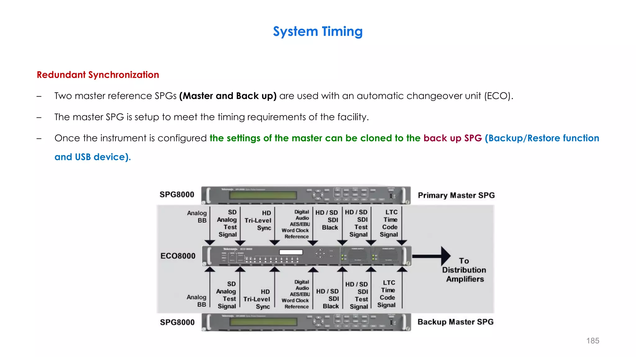
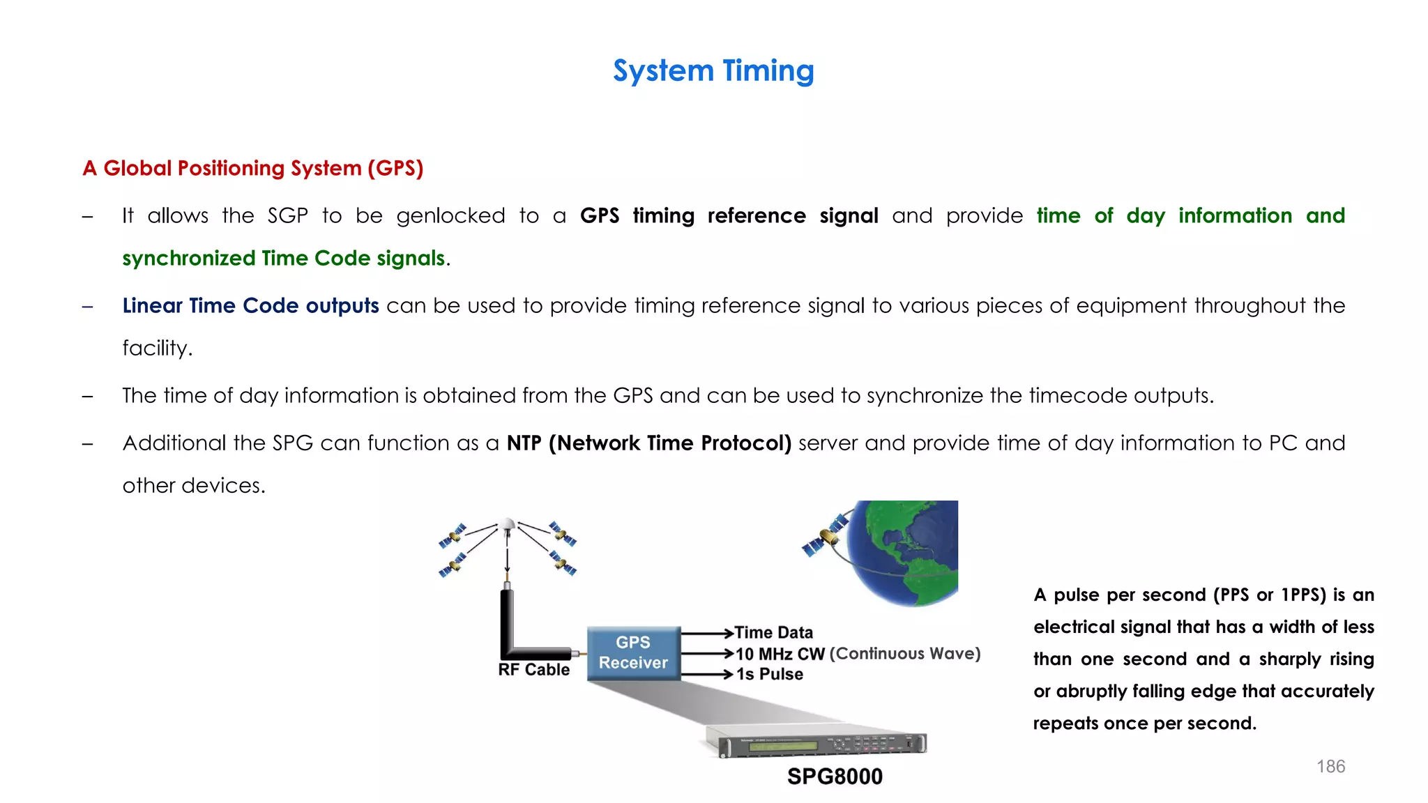
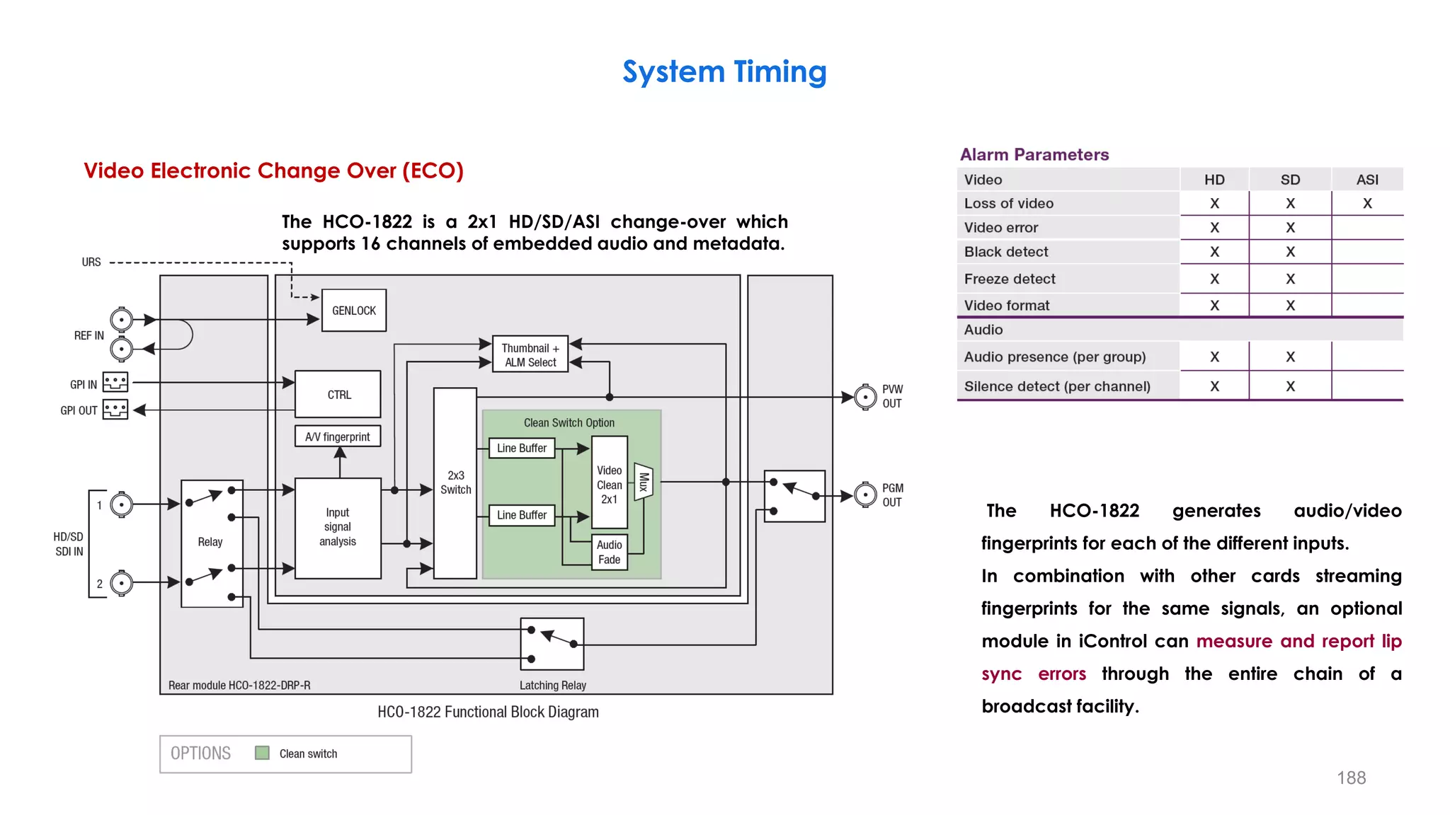
Downloaded 62 times


![𝑠 = 𝑐. 𝑟𝛾
𝜸 < 𝟏
It maps a narrow range of
dark input values into a wide
range of output values and
vice versa.
Brighter Image
𝜸 > 𝟏
It maps a narrow range of
bright input values into a wide
range of output values and
vice versa.
Darker Image
105
r = [1 10 20 30 40 210 220 230 240 250 255]
s( =0.4) = [28 70 92 108 122 236 240 245 249 253 255]
s( = 2.5) = [0 0 0 1 2 157 176 197 219 243 255]
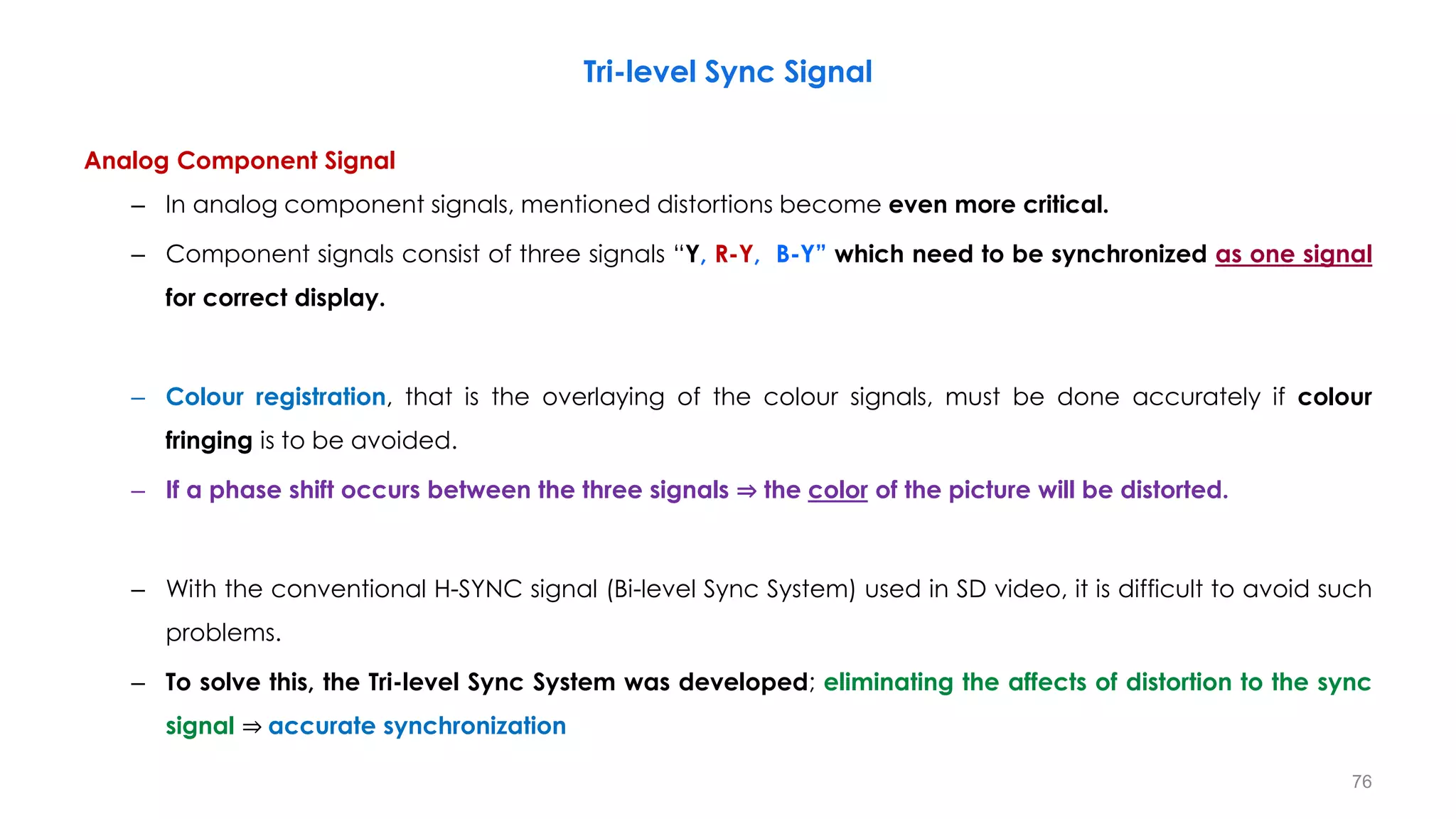
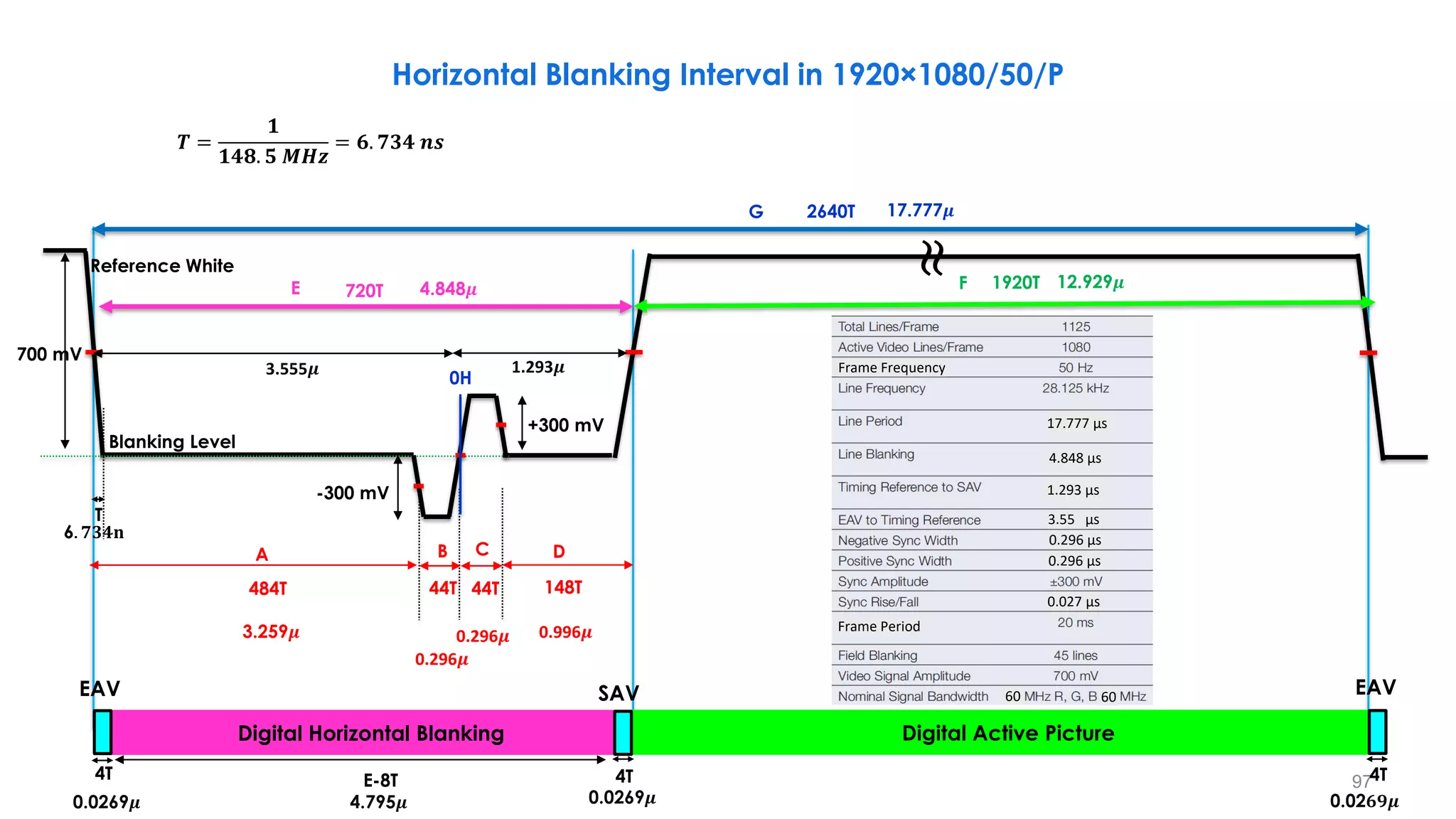
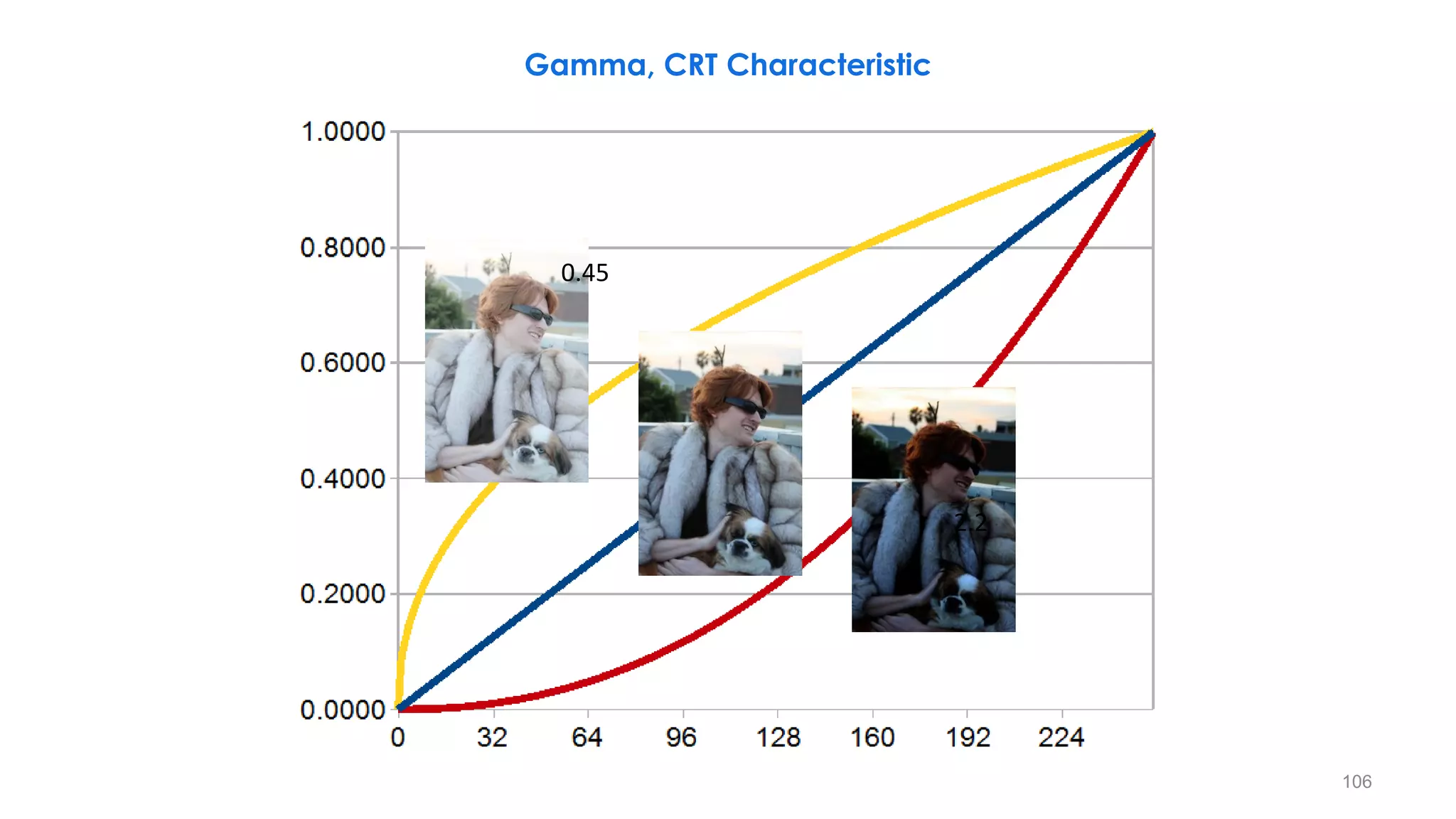
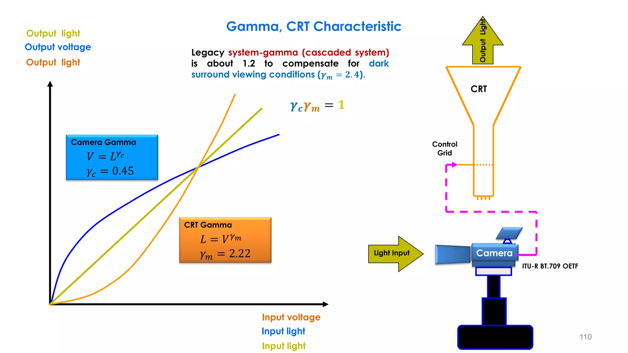
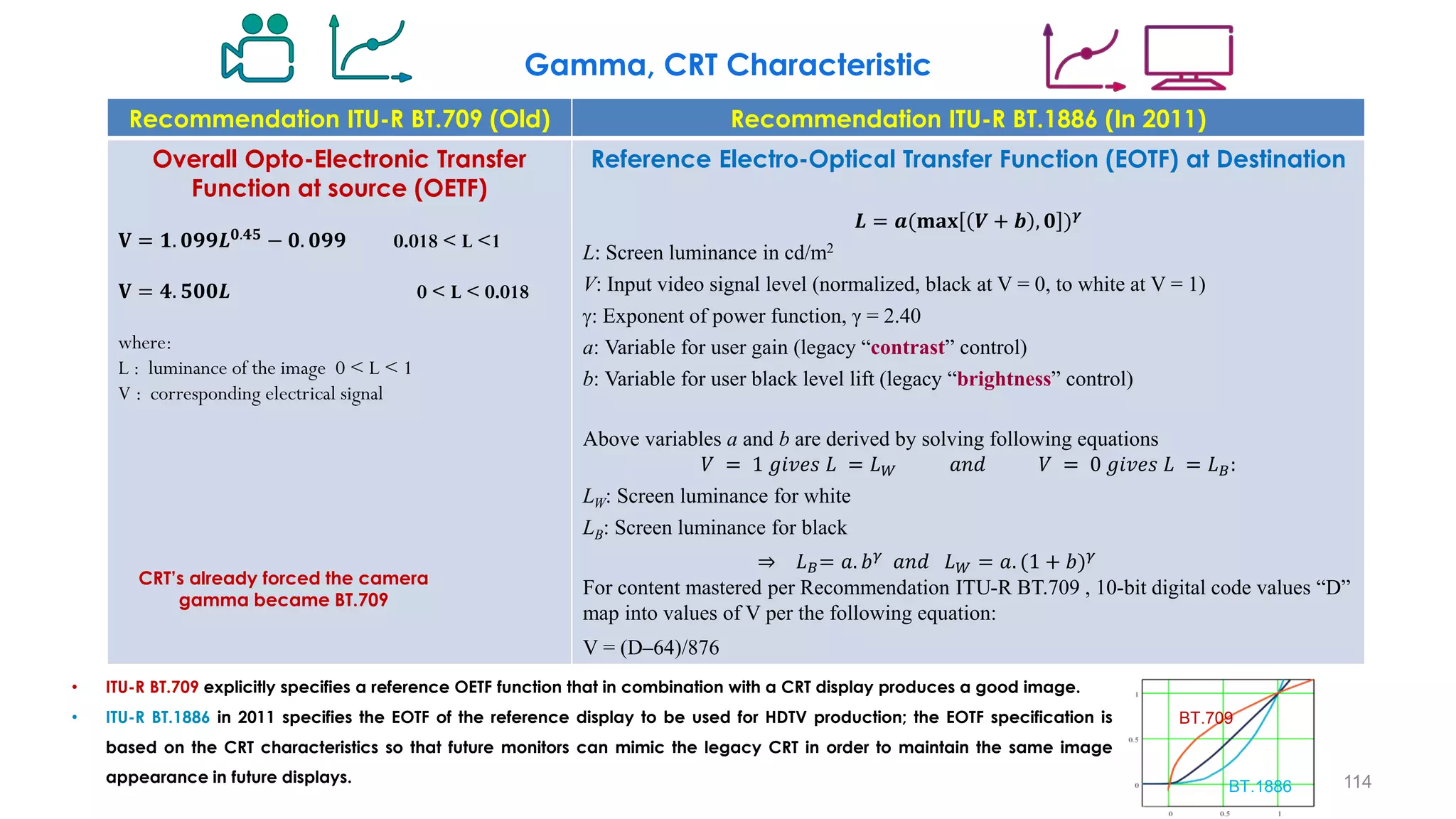
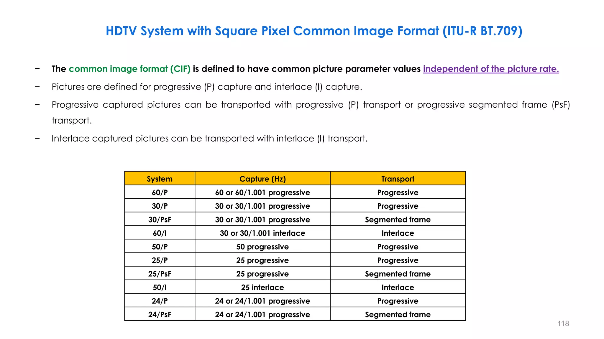
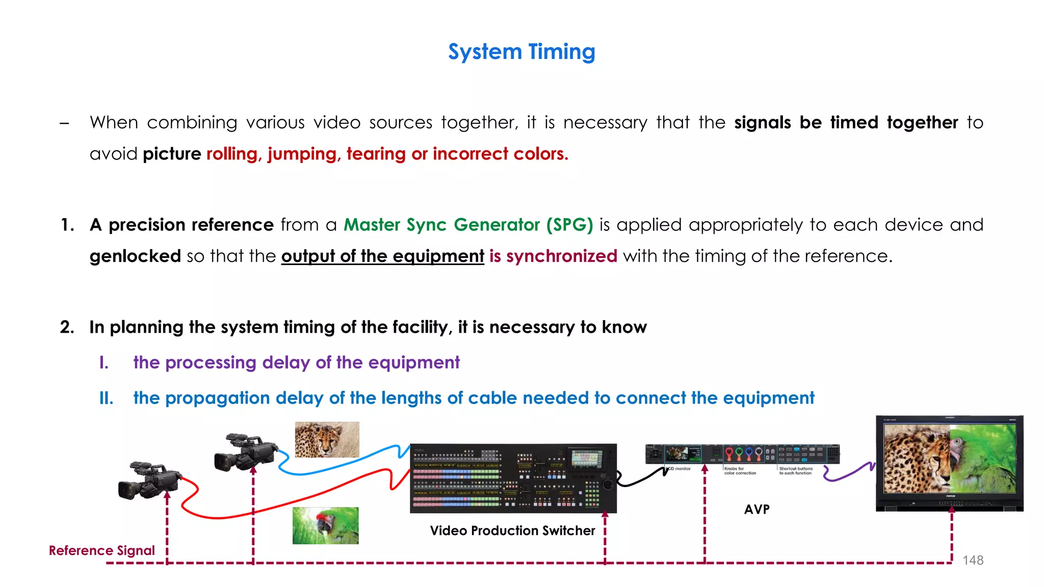
Gamma, CRT Characteristic
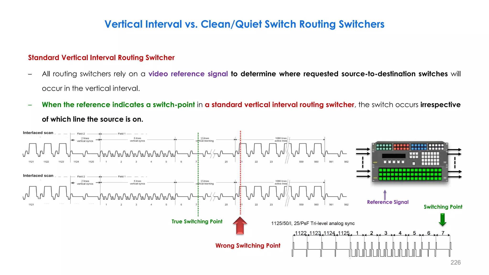
− Plots of the gamma
equation 𝑠 = 𝑐. 𝑟𝛾
for
various values of g (c =
1 in all cases).
− Each curve was scaled
independently so that
all curves would fit in
the same graph.
− Our interest here is on
the shapes of the
curves, not on their
relative values.](https://image.slidesharecdn.com/anintroductiontohdtvprinciples-part1-210122062607/75/An-Introduction-to-HDTV-Principles-Part-1-105-2048.jpg)
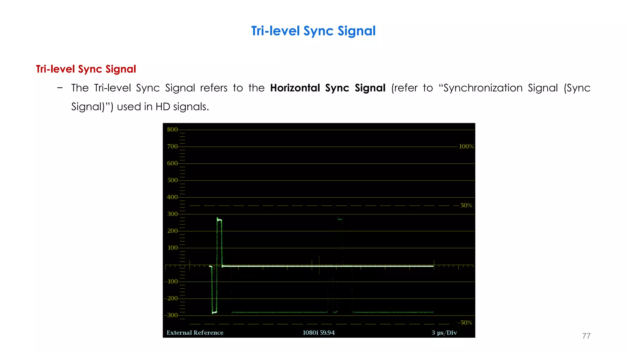
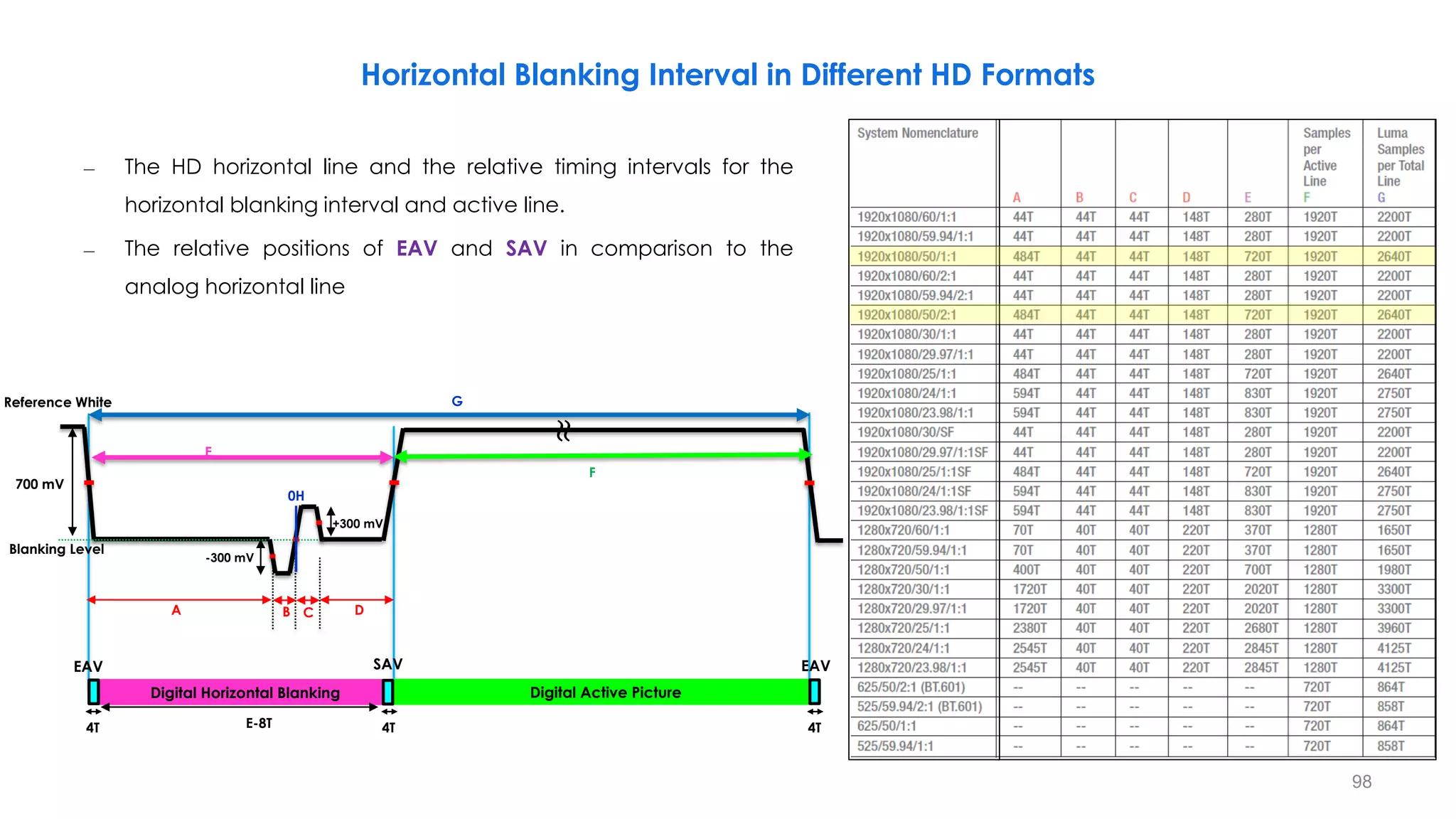
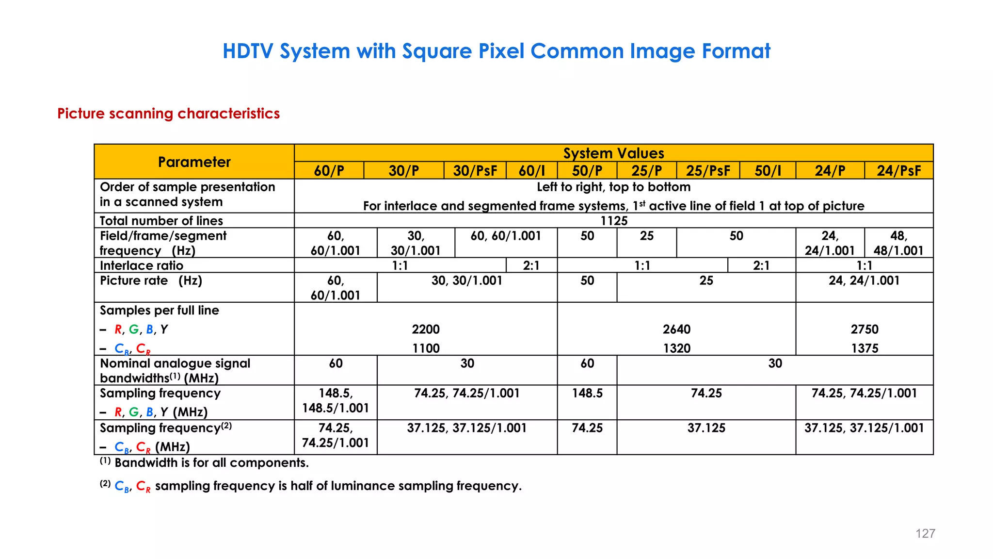
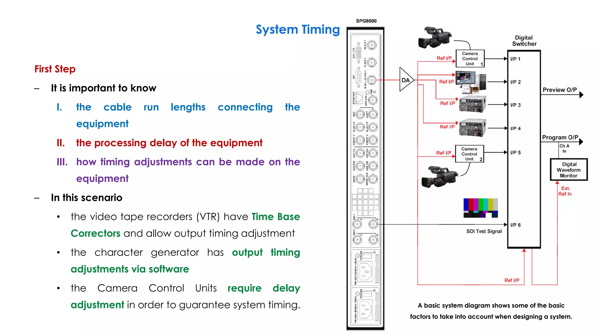
![121
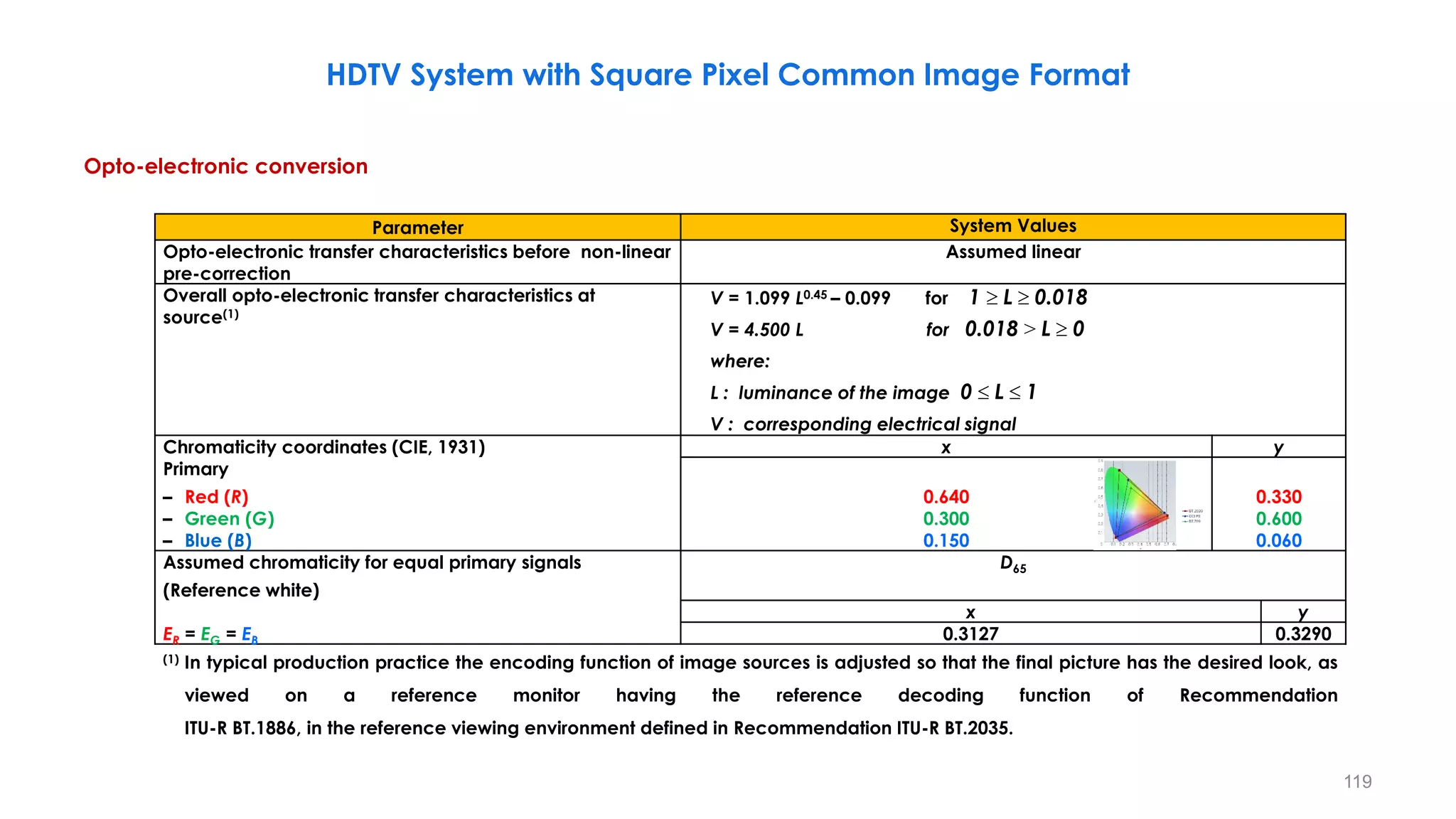
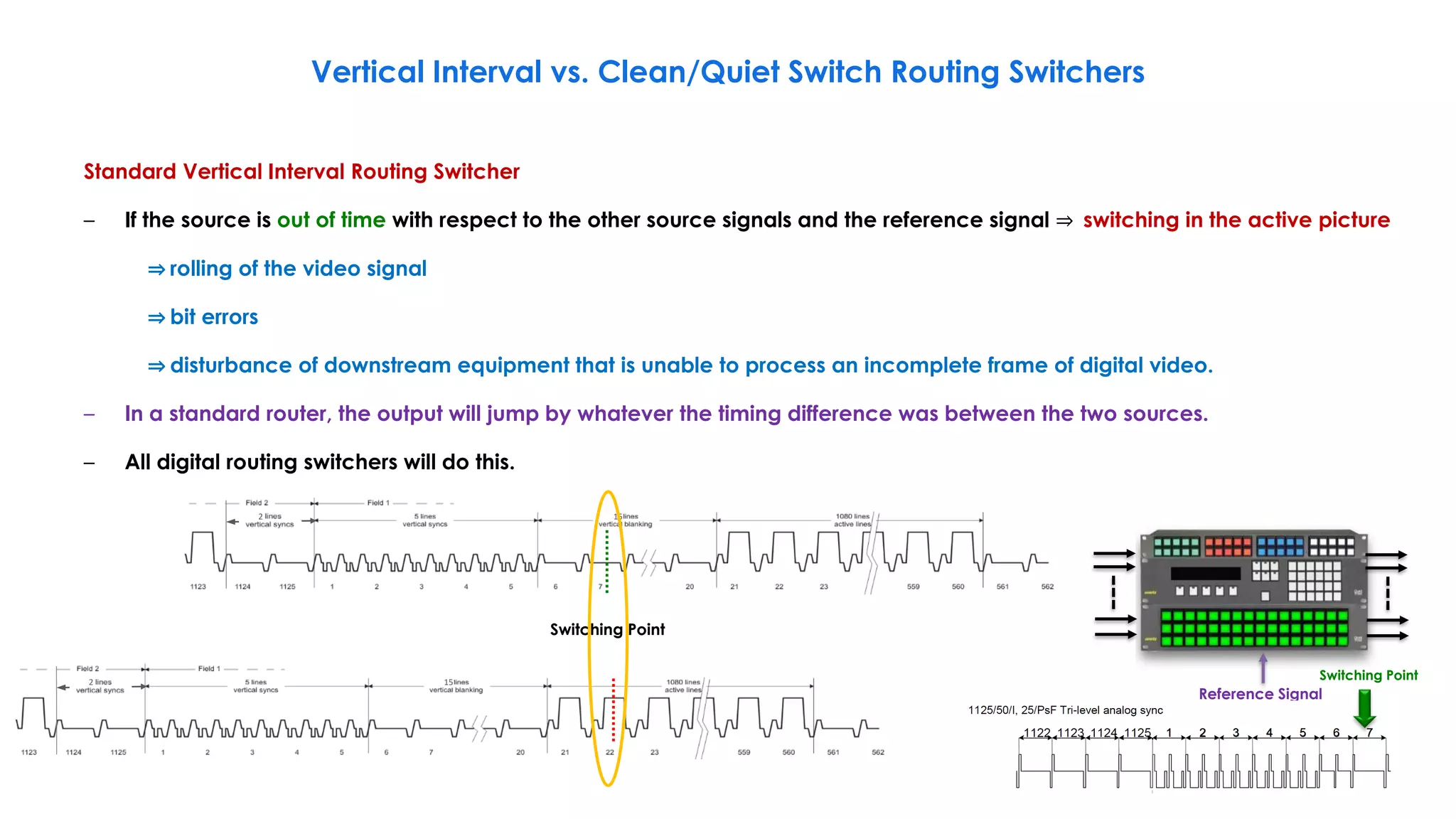
Parameter System Values
Conceptual non-linear pre-correction of primary signals 𝜸 = 𝟎. 𝟒𝟓
Derivation of luminance signal ሖ
𝑬𝒀 = 𝟎. 𝟐𝟏𝟐𝟔 ሖ
𝑬𝑹 + 𝟎. 𝟕𝟏𝟓𝟐 ሖ
𝑬𝑮 + 𝟎. 𝟎𝟕𝟐𝟐 ሖ
𝑬𝑩
Derivation of colour-difference signal (analogue coding)
ሖ
𝑬𝑪𝑩 =
ሖ
𝑬𝑩 − ሖ
𝑬𝒀
𝟏. 𝟖𝟓𝟓𝟔
=
−𝟎. 𝟐𝟏𝟐𝟔 ሖ
𝑬𝑹 + 𝟎. 𝟕𝟏𝟓𝟐 ሖ
𝑬𝑮 + 𝟎. 𝟗𝟐𝟕𝟖 ሖ
𝑬𝑩
𝟏. 𝟖𝟓𝟓𝟔
ሖ
𝑬𝑪𝑹 =
ሖ
𝑬𝑹 − ሖ
𝑬𝒀
𝟏. 𝟓𝟕𝟒𝟖
=
𝟎. 𝟕𝟖𝟕𝟒 ሖ
𝑬𝑹 − 𝟎. 𝟕𝟏𝟓𝟐 ሖ
𝑬𝑮 − 𝟎. 𝟎𝟕𝟐𝟐 ሖ
𝑬𝑩
𝟏. 𝟓𝟕𝟒𝟖
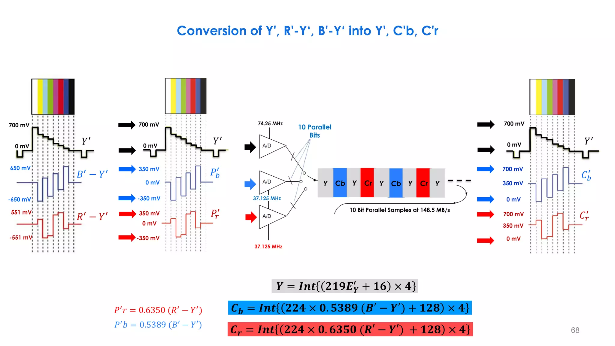
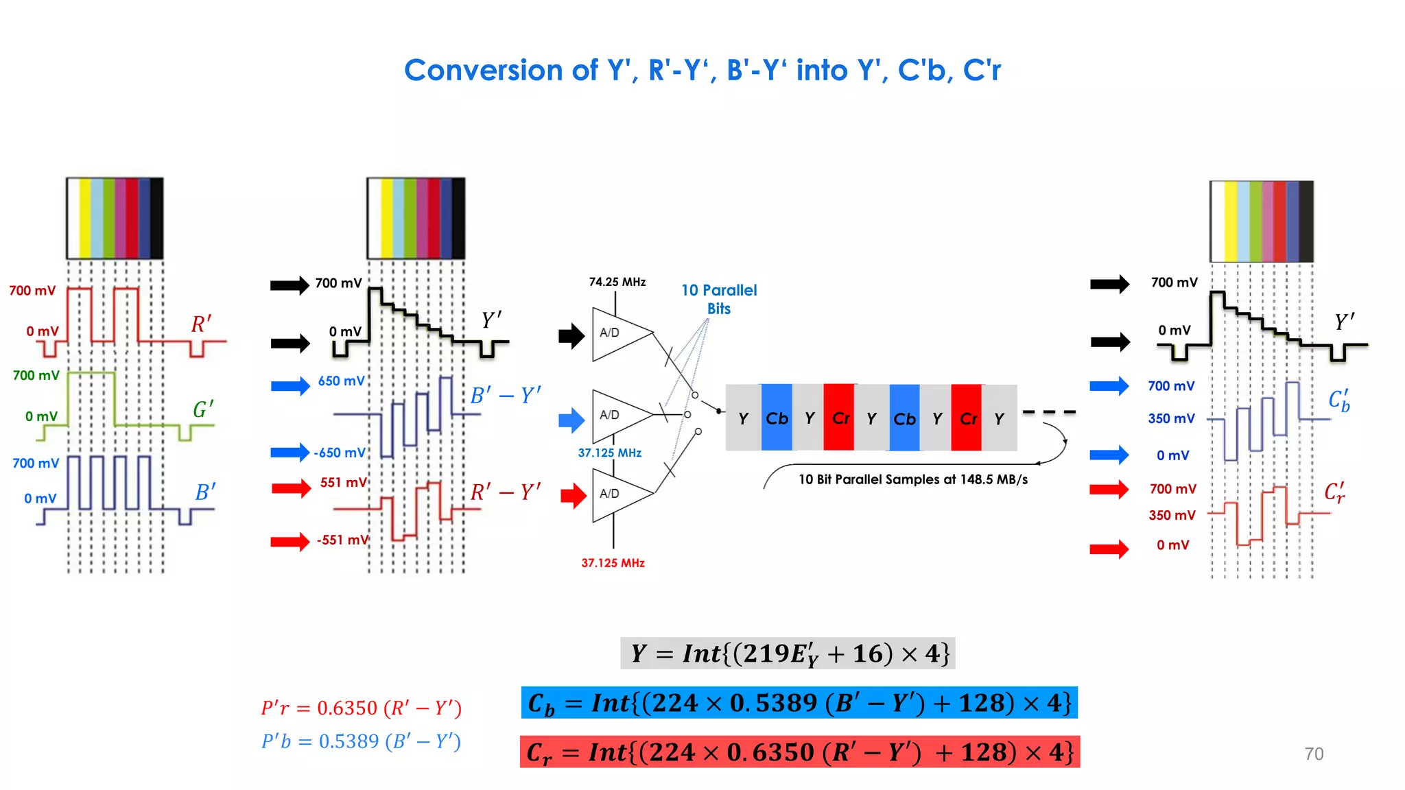
Quantization of RGB, luminance and colour-difference signals(1), (2) ሖ
𝑫𝑹 = 𝑰𝑵𝑻[ 𝟐𝟏𝟗 ሖ
𝑬𝑹 + 𝟏𝟔 . 𝟐𝒏−𝟖]
ሖ
𝑫𝑮 = 𝑰𝑵𝑻[ 𝟐𝟏𝟗 ሖ
𝑬𝑮 + 𝟏𝟔 . 𝟐𝒏−𝟖]
ሖ
𝑫𝑩 = 𝑰𝑵𝑻[ 𝟐𝟏𝟗 ሖ
𝑬𝑩 + 𝟏𝟔 . 𝟐𝒏−𝟖]
ሖ
𝑫𝒀 = 𝑰𝑵𝑻[ 𝟐𝟏𝟗 ሖ
𝑬𝒀 + 𝟏𝟔 . 𝟐𝒏−𝟖]
ሖ
𝑫𝑪𝑩 = 𝑰𝑵𝑻[ 𝟐𝟐𝟒 ሖ
𝑬𝑪𝑩 + 𝟏𝟐𝟖 . 𝟐𝒏−𝟖]
ሖ
𝑫𝑪𝑹 = 𝑰𝑵𝑻[ 𝟐𝟐𝟒 ሖ
𝑬𝑪𝑹 + 𝟏𝟐𝟖 . 𝟐𝒏−𝟖]
Derivation of luminance and colour-difference signals via quantized RGB signals ሖ
𝑫𝒀 = 𝑰𝑵𝑻[𝟎. 𝟐𝟏𝟐𝟔 ሖ
𝑫𝑹 + 𝟎. 𝟕𝟏𝟓𝟐 ሖ
𝑫𝑮 + 𝟎. 𝟎𝟕𝟐𝟐 ሖ
𝑫𝑩]
ሖ
𝑫𝑪𝑩 = 𝑰𝑵𝑻[ −
𝟎.𝟐𝟏𝟐𝟔
𝟏.𝟖𝟓𝟓𝟔
ሖ
𝑫𝑹 −
𝟎.𝟕𝟏𝟓𝟐
𝟏.𝟖𝟓𝟓𝟔
ሖ
𝑫𝑮 +
𝟎.𝟗𝟐𝟕𝟖
𝟏.𝟖𝟓𝟓𝟔
ሖ
𝑫𝑩 .
𝟐𝟐𝟒
𝟐𝟏𝟗
+𝟐𝒏−𝟏]
ሖ
𝑫𝑪𝑹 = 𝑰𝑵𝑻[ −
𝟎.𝟕𝟖𝟕𝟒
𝟏.𝟓𝟕𝟒𝟖
ሖ
𝑫𝑹 −
𝟎.𝟕𝟏𝟓𝟐
𝟏.𝟓𝟕𝟒𝟖
ሖ
𝑫𝑮 −
𝟎.𝟎𝟕𝟐𝟐
𝟏.𝟓𝟕𝟒𝟖
ሖ
𝑫𝑩 .
𝟐𝟐𝟒
𝟐𝟏𝟗
+𝟐𝒏−𝟏]
(1)“n” denotes the number of the bit length of the quantized signal.
(2)The operator INT returns the value of 0 for fractional parts in the range of 0 to 0.4999... and +1 for fractional parts in the range of 0.5 to 0.9999..., i.e. it rounds up
fractions above 0.5.
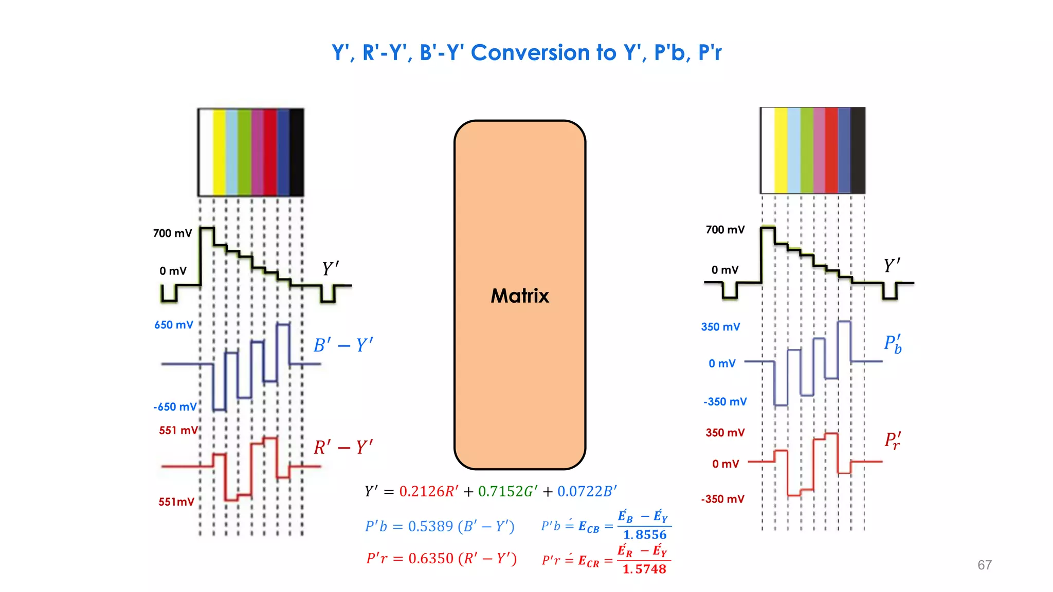
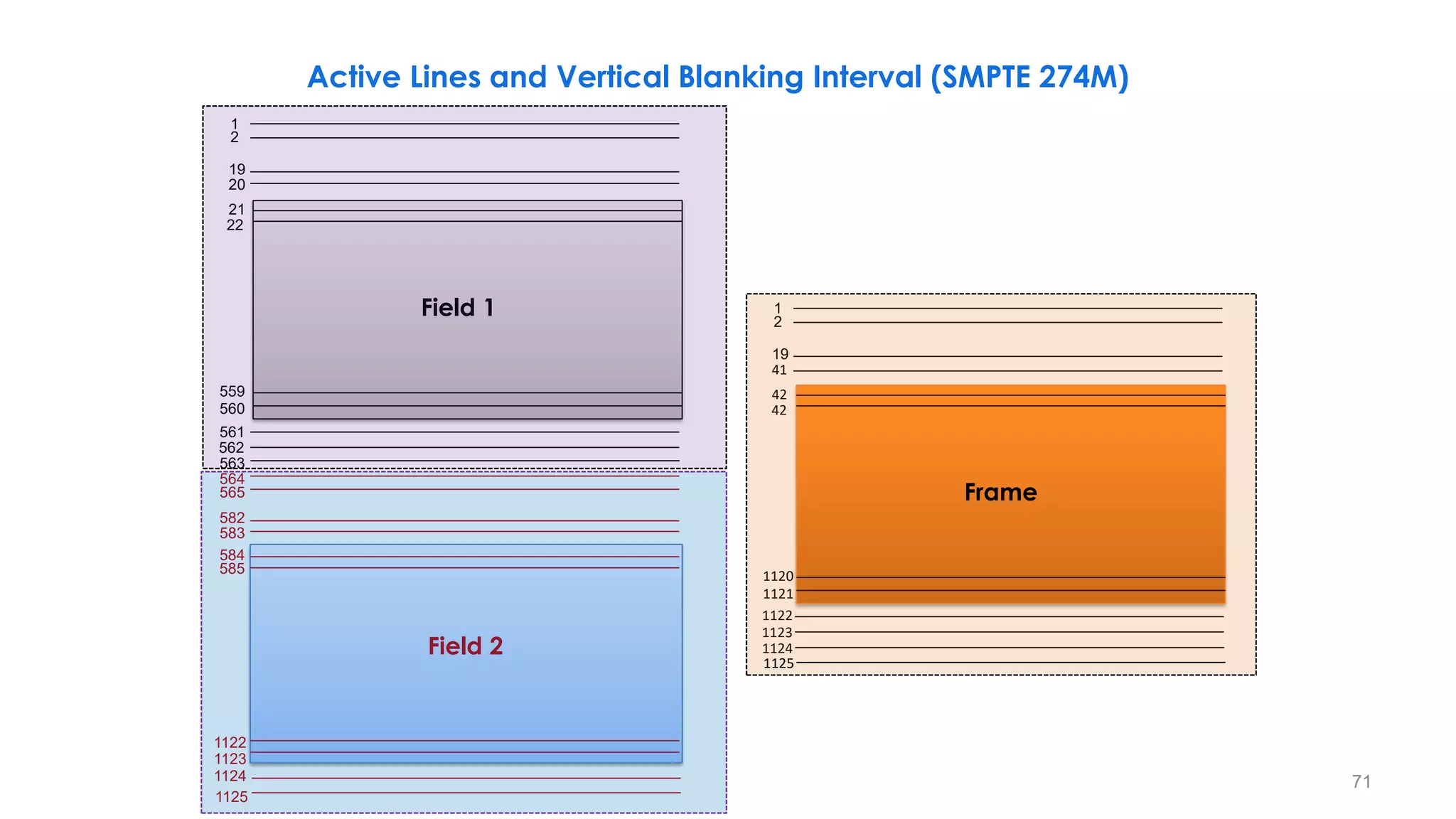
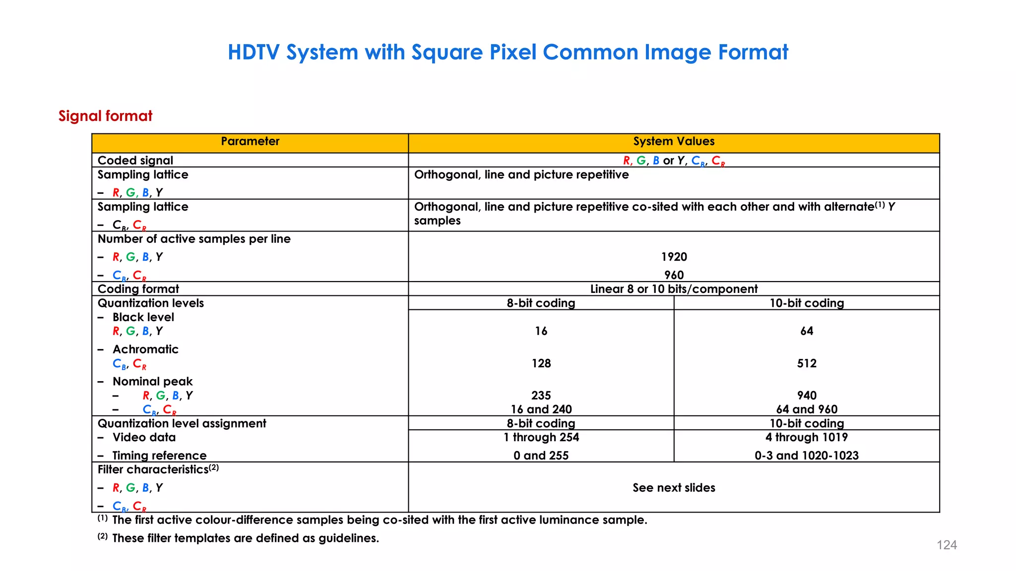
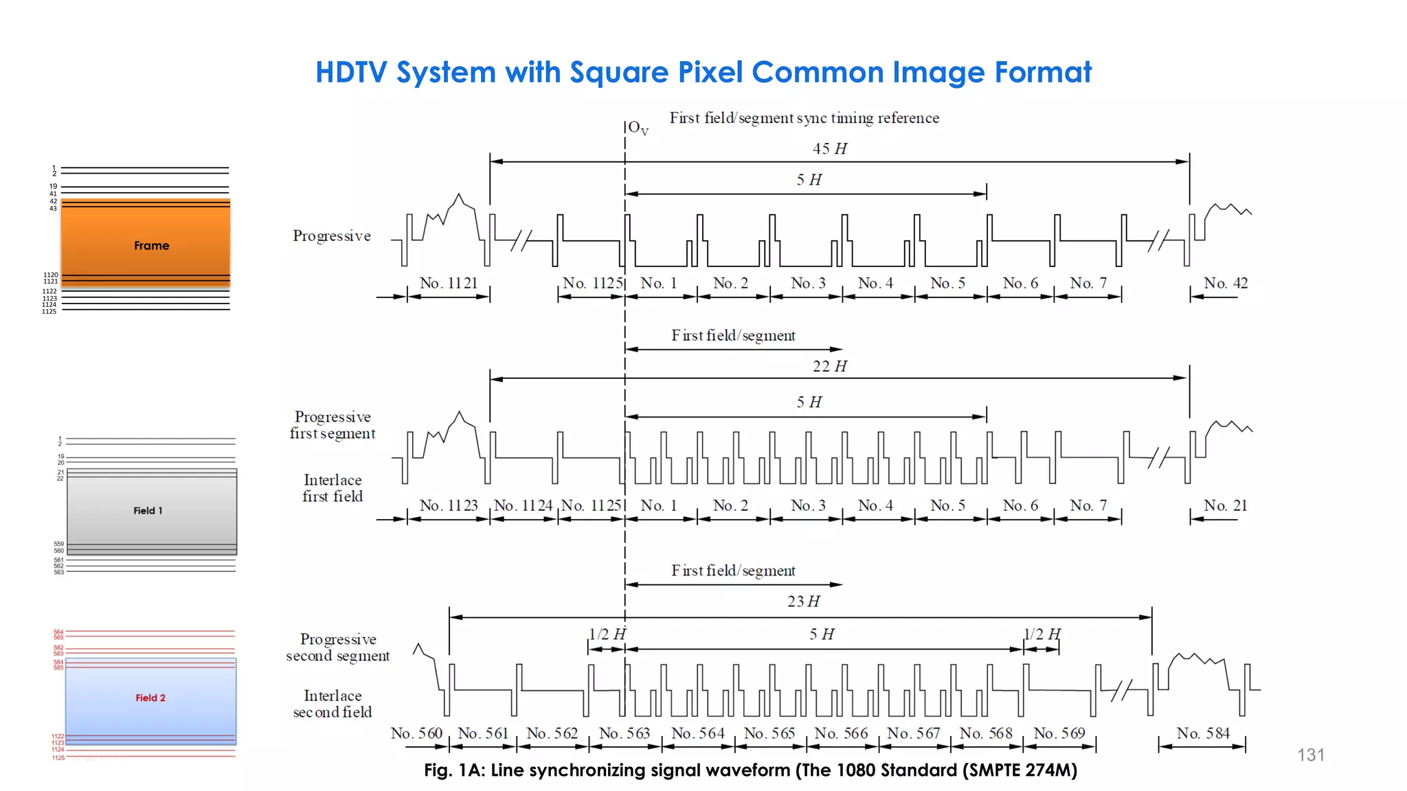
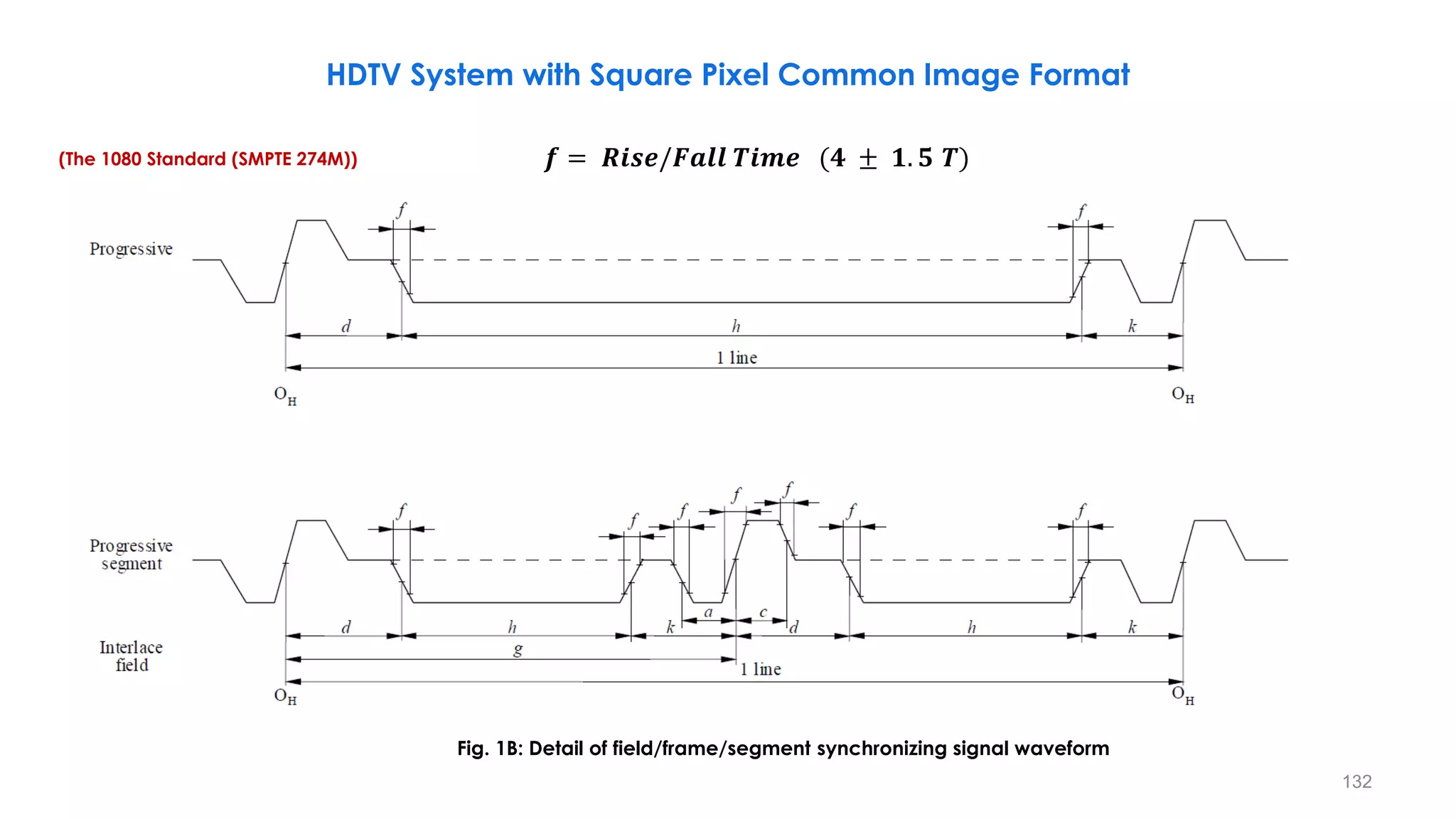
Signal format
HDTV System with Square Pixel Common Image Format
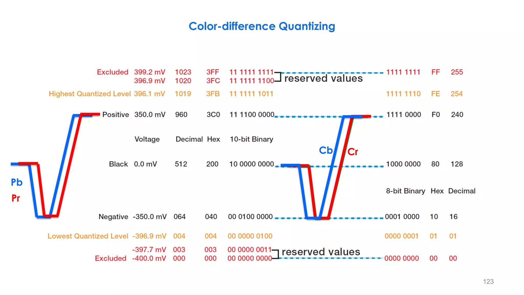
𝑃′
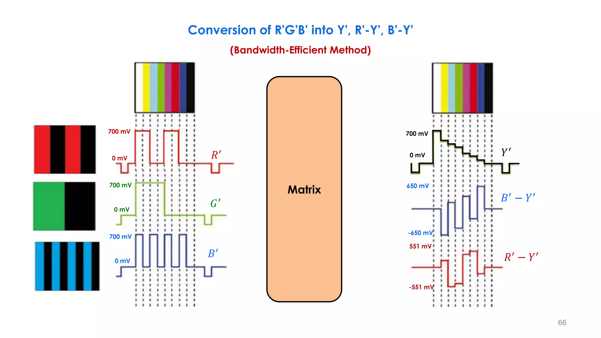
𝑏 = 0.5389 (𝐵′ − 𝑌′) ሖ
= 𝑬𝑪𝑩=
ሖ
𝑬𝑩 − ሖ
𝑬𝒀
𝟏. 𝟖𝟓𝟓𝟔
𝑃′
𝑟 = 0.6350 𝑅′
− 𝑌′
= ሖ
𝑬𝑪𝑹 =
ሖ
𝑬𝑹 − ሖ
𝑬𝒀
𝟏.𝟓𝟕𝟒𝟖](https://image.slidesharecdn.com/anintroductiontohdtvprinciples-part1-210122062607/75/An-Introduction-to-HDTV-Principles-Part-1-121-2048.jpg)

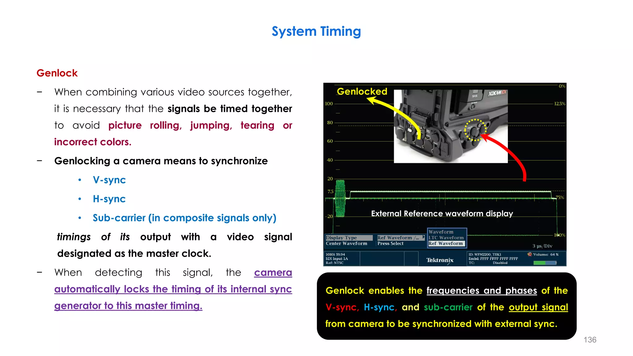
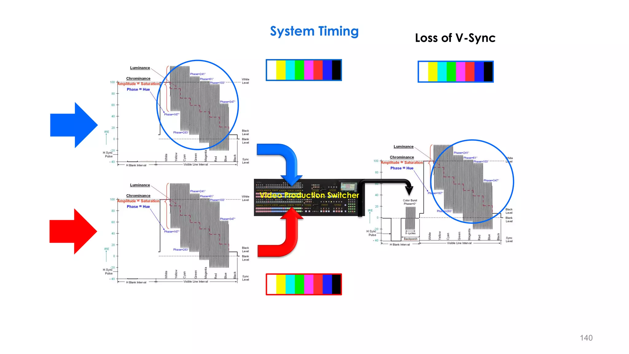
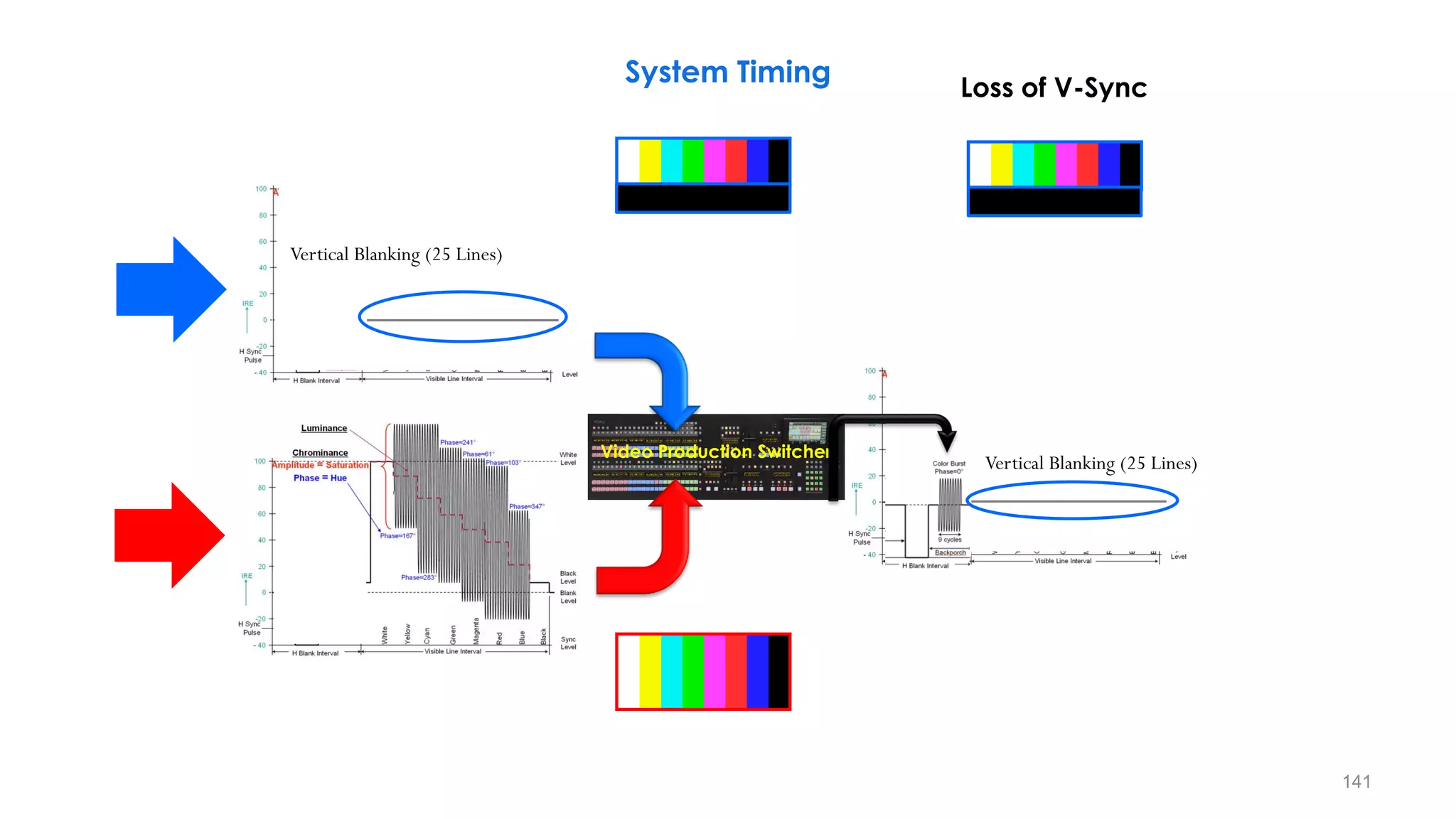
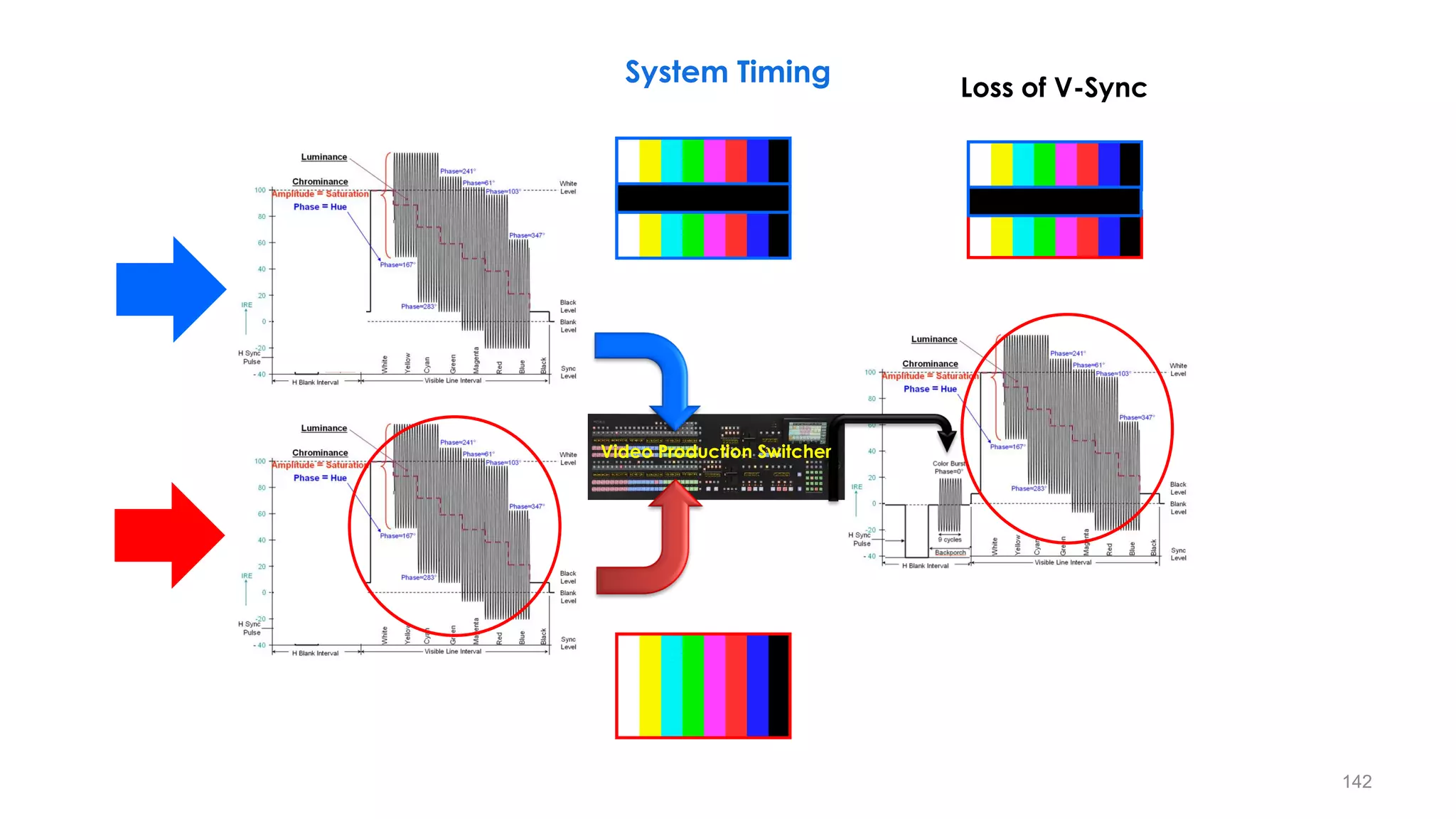

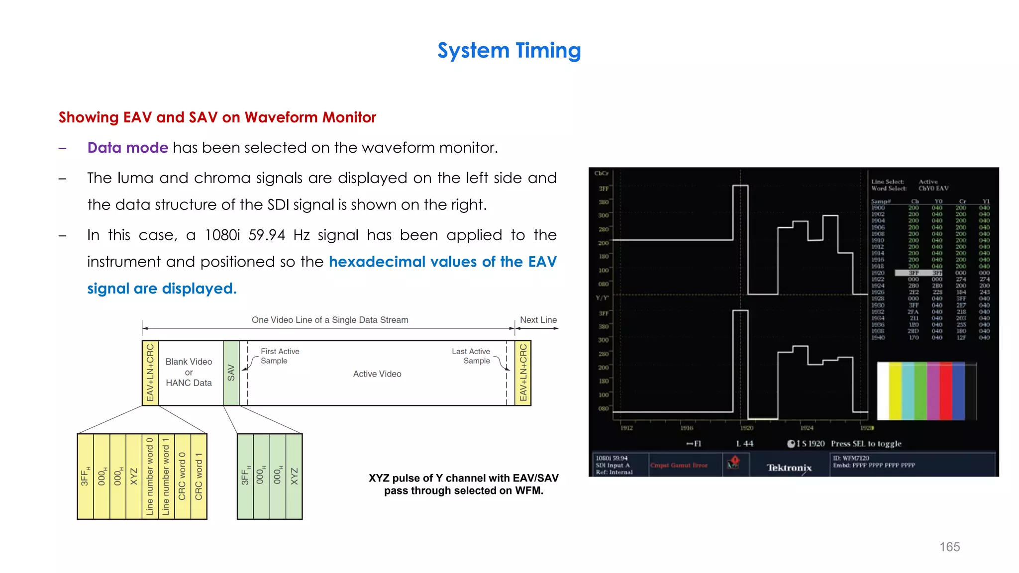

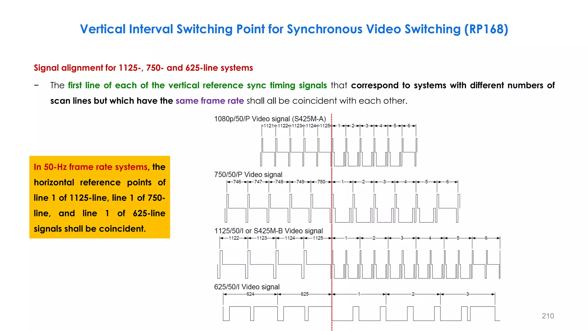

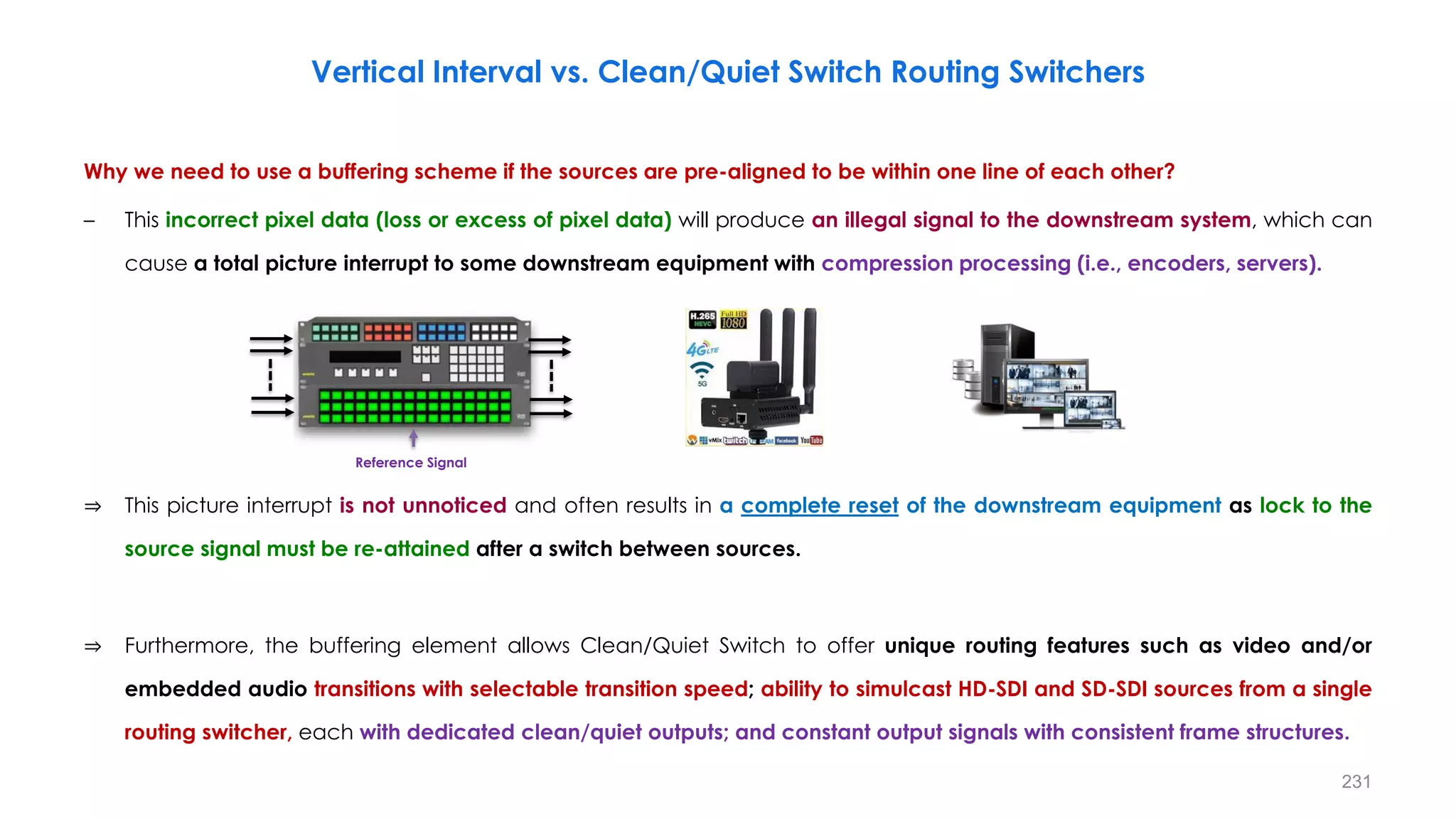


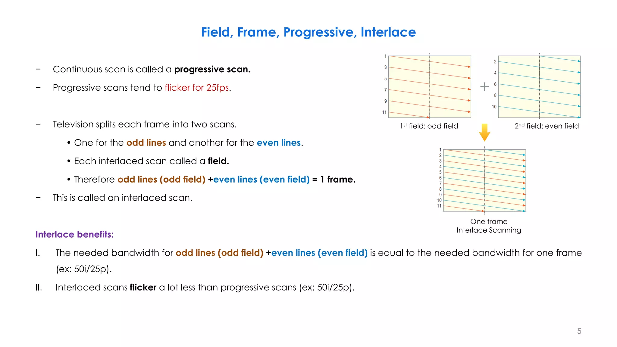
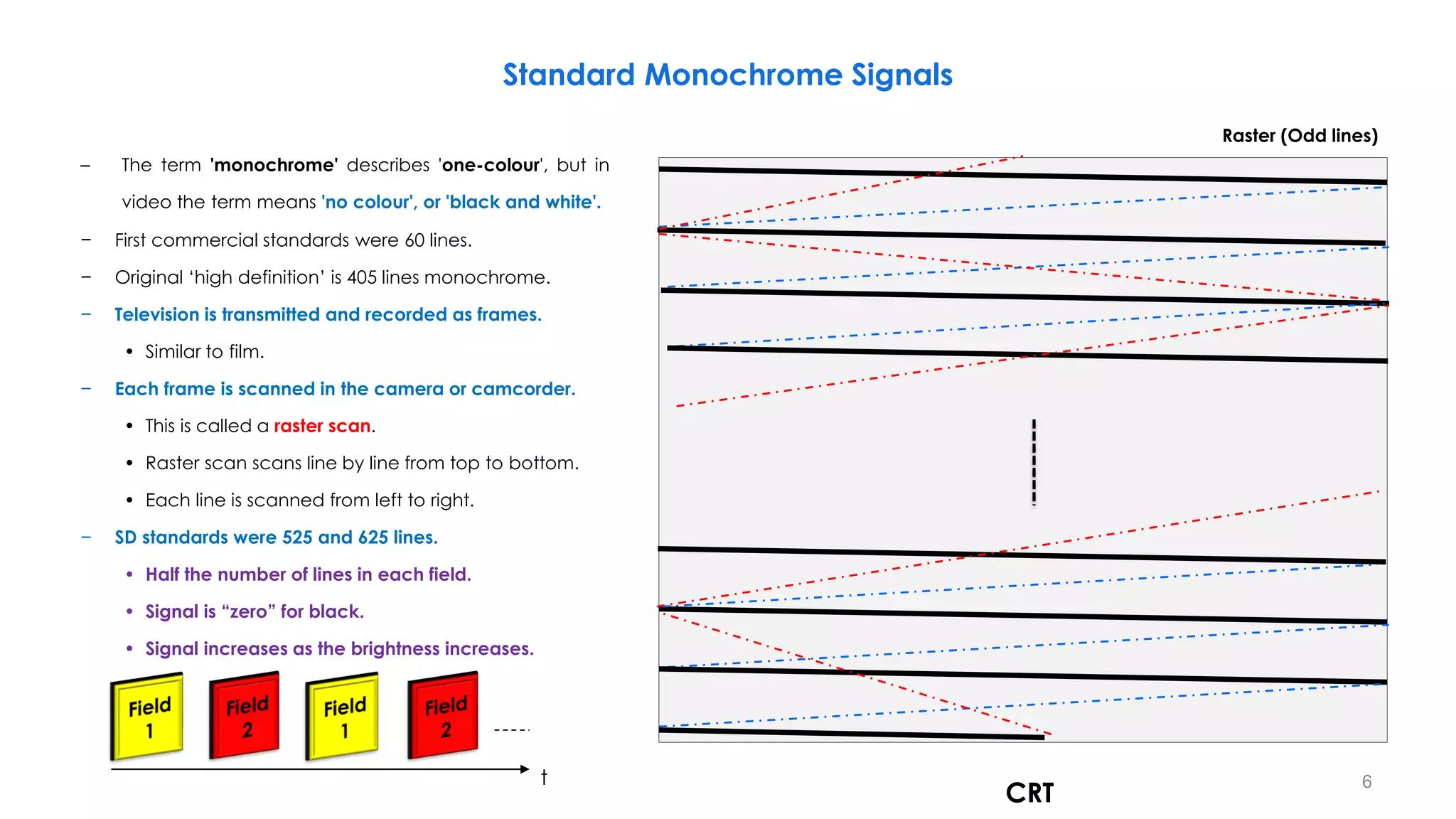
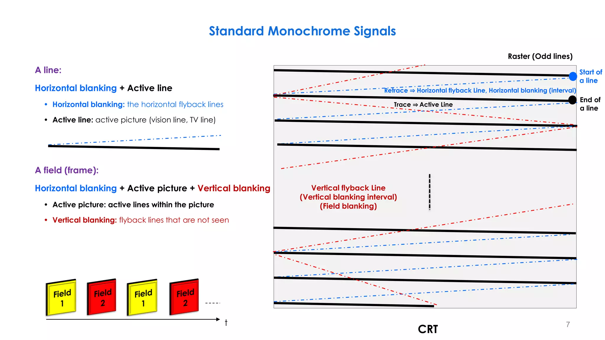
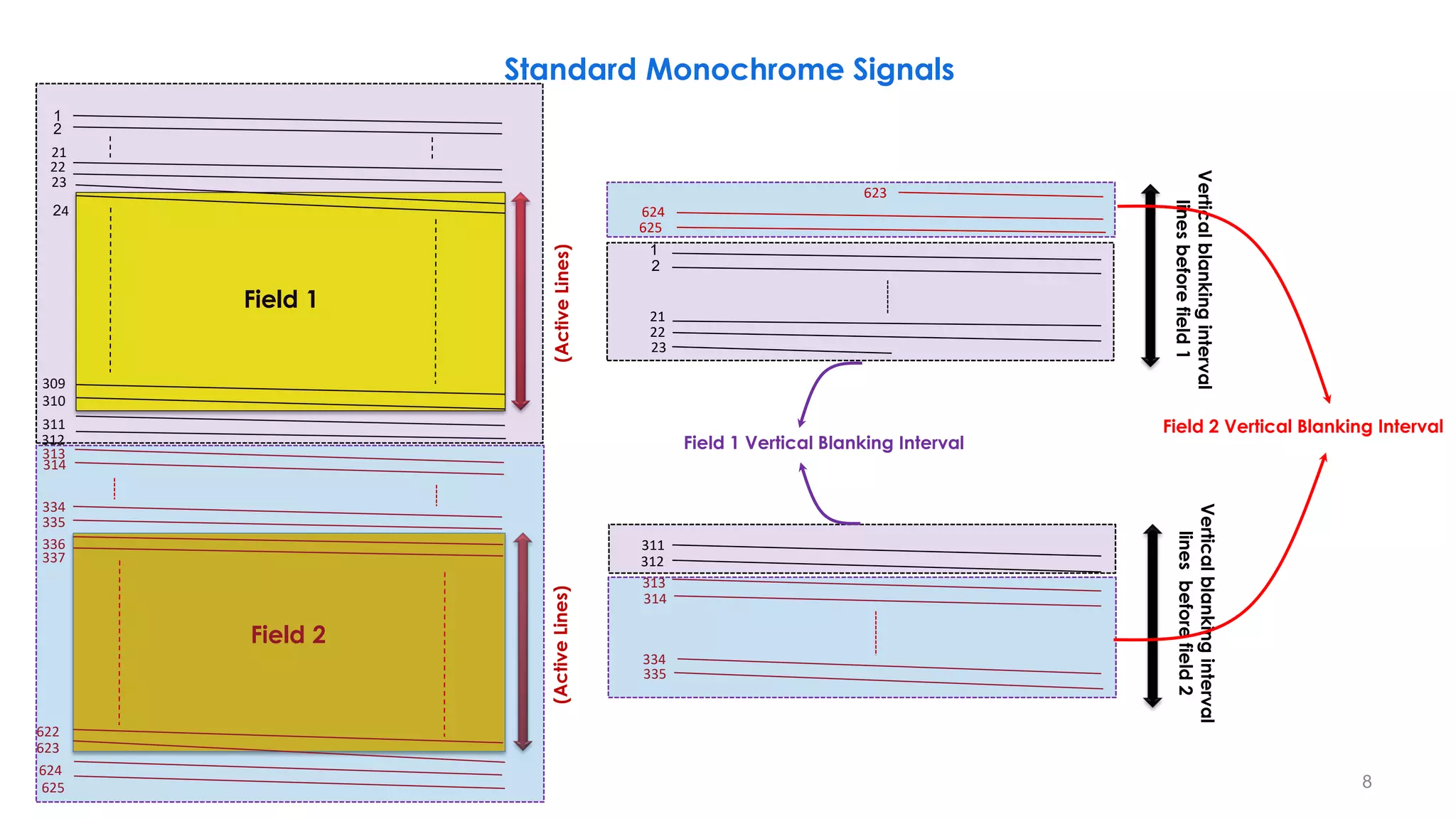
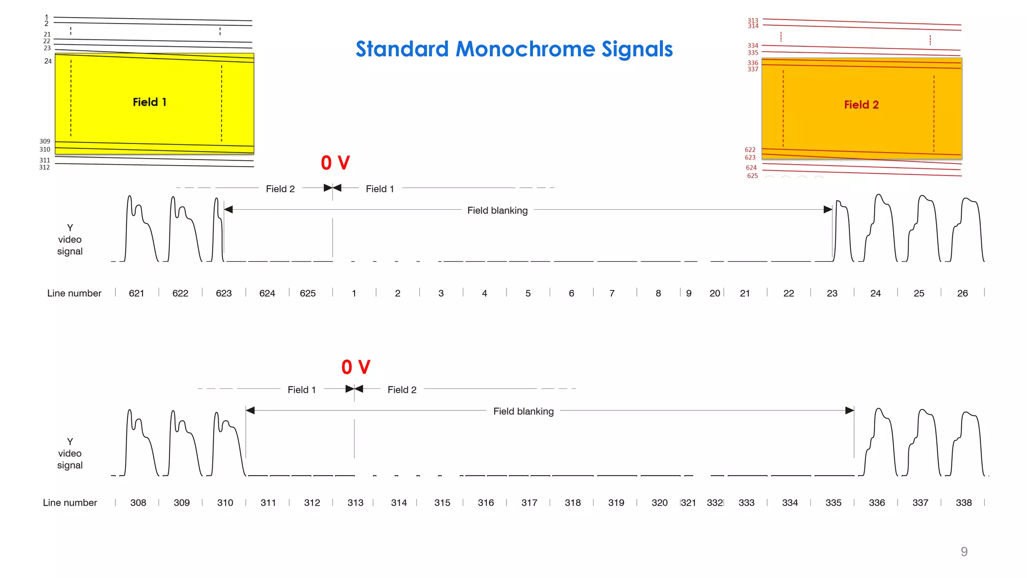
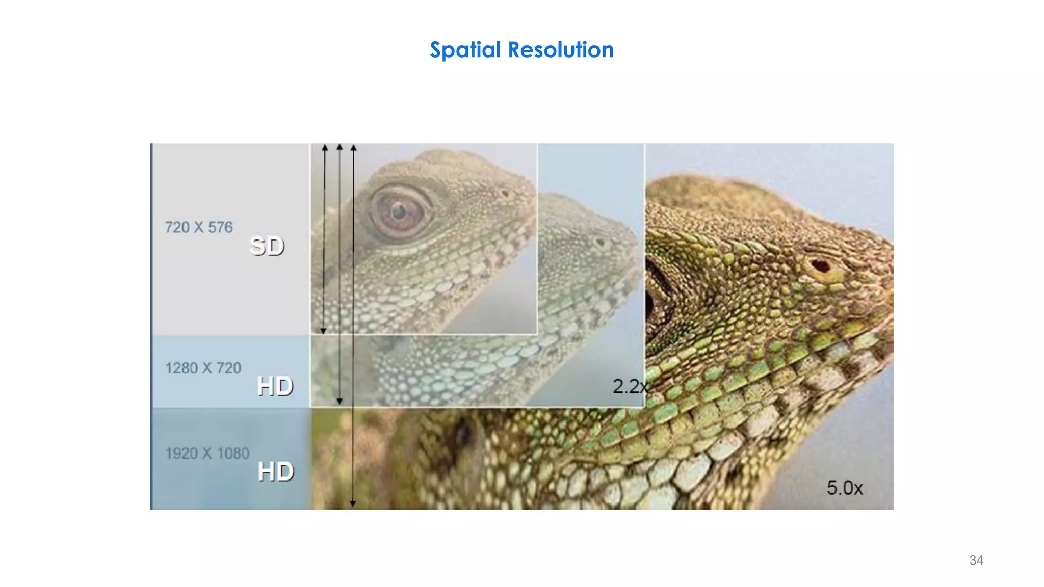
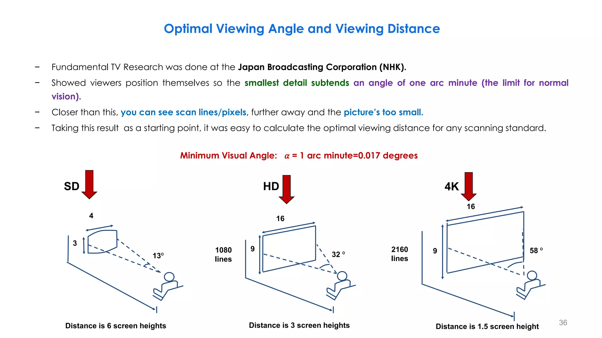
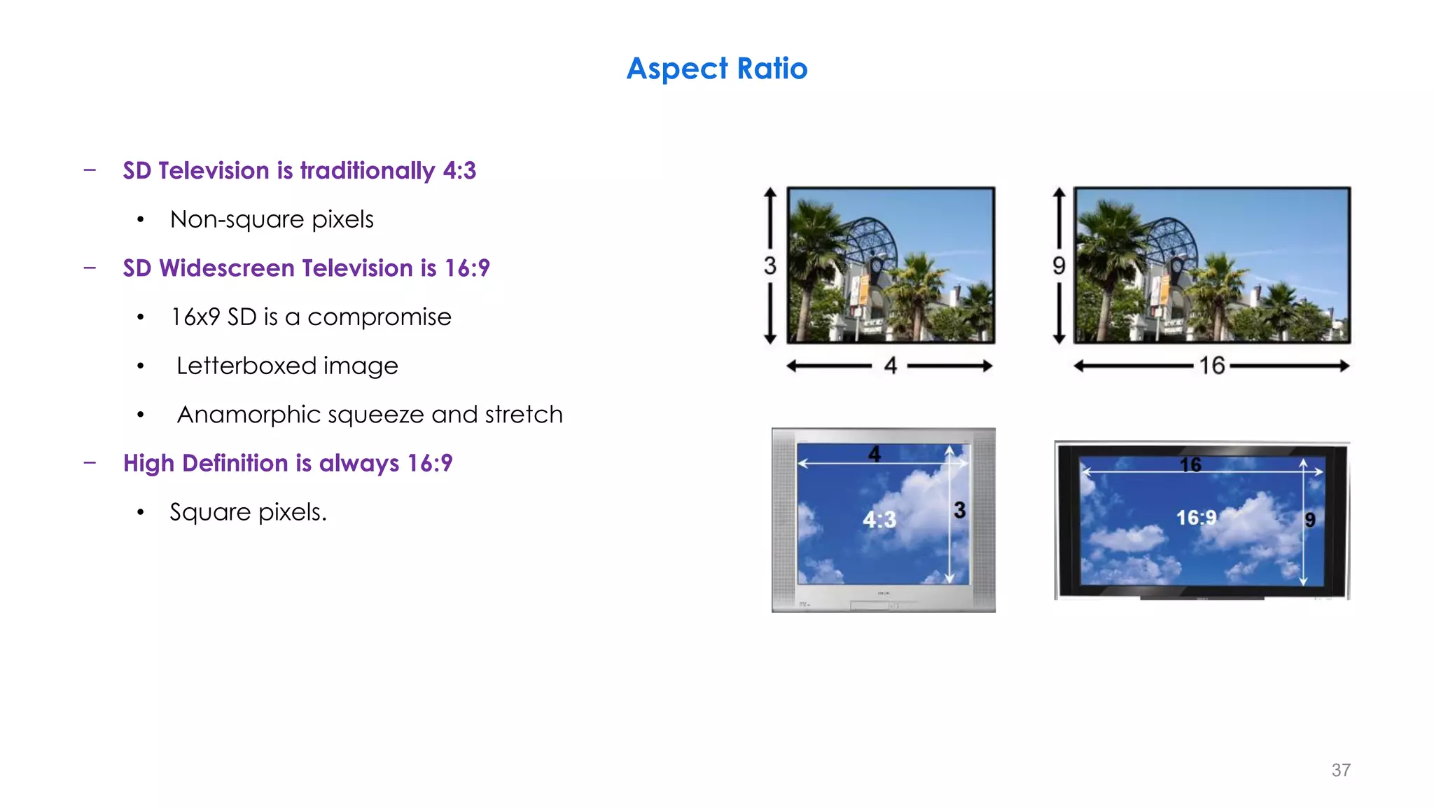
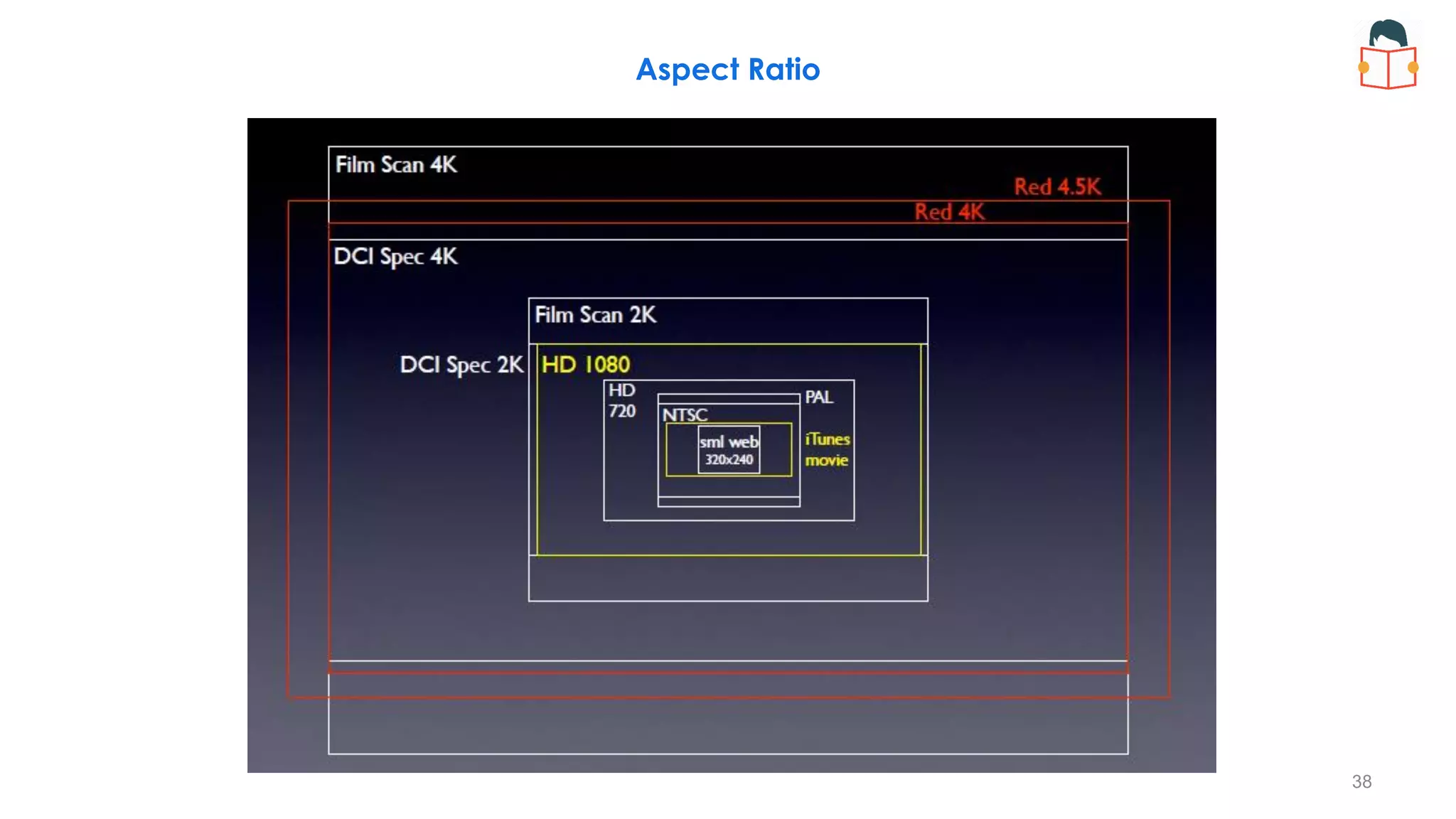
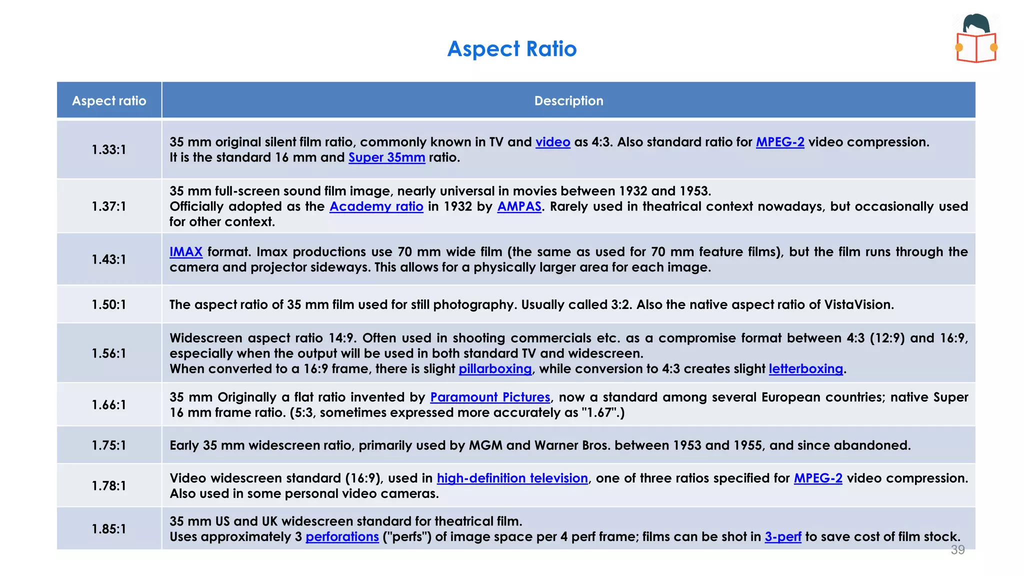
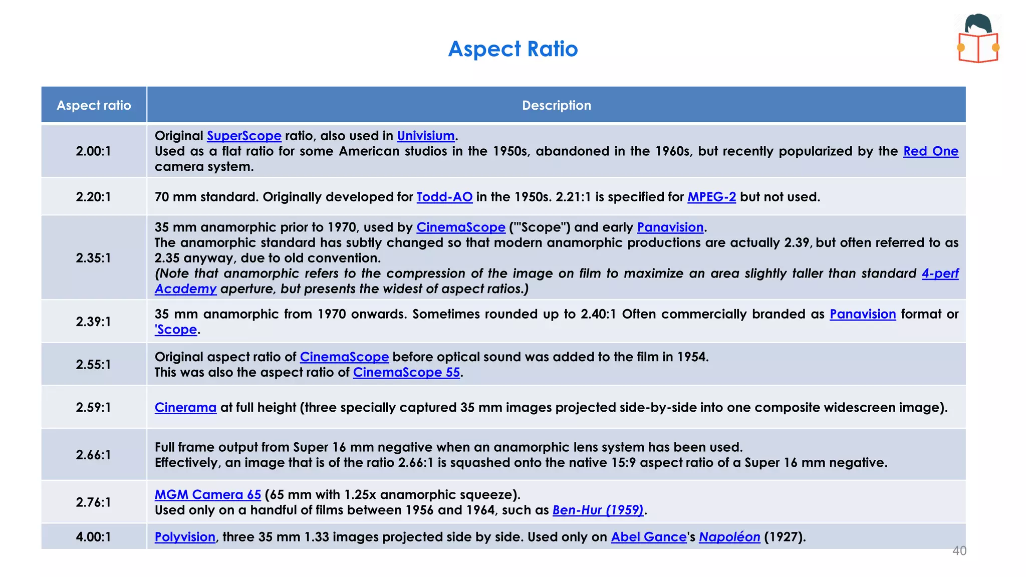
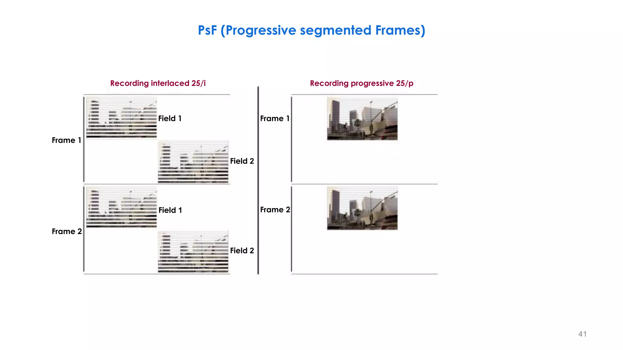
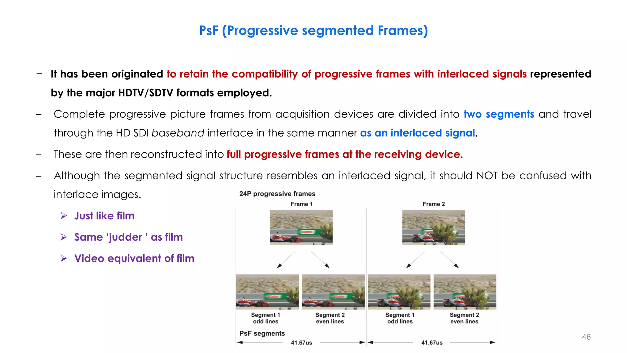
This document provides an overview of video standards and concepts related to standard definition television (SDTV) and high definition television (HDTV). It begins with definitions of key terms like interlacing, progressive scanning, and frame rates. It then covers standards for monochrome signals, including signal timings, synchronization pulses, and blanking intervals. Digital SDTV standards like line counts, field structures, and ancillary data space are also summarized. The document concludes with discussions of spatial resolution, optimal viewing distances, and different aspect ratios used in television.


![Tv 101[1]](https://cdn.slidesharecdn.com/ss_thumbnails/tv1011-12648274753543-phpapp01-thumbnail.jpg?width=640&height=640&fit=bounds)