ComponentDiagramComponentDiagram
Preeti Mishra
Course Instructor
INTRODUCTION
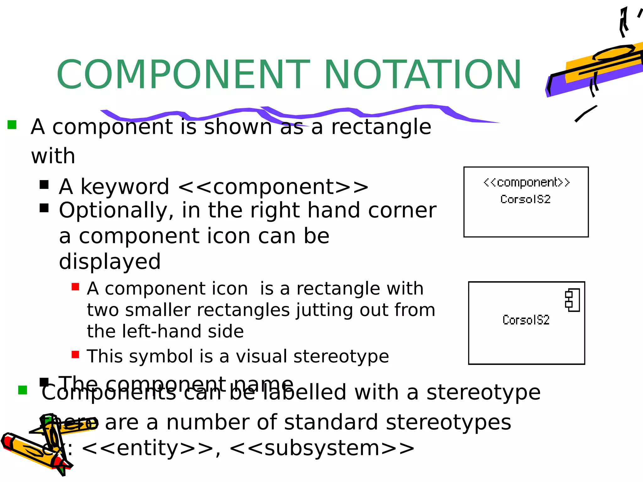
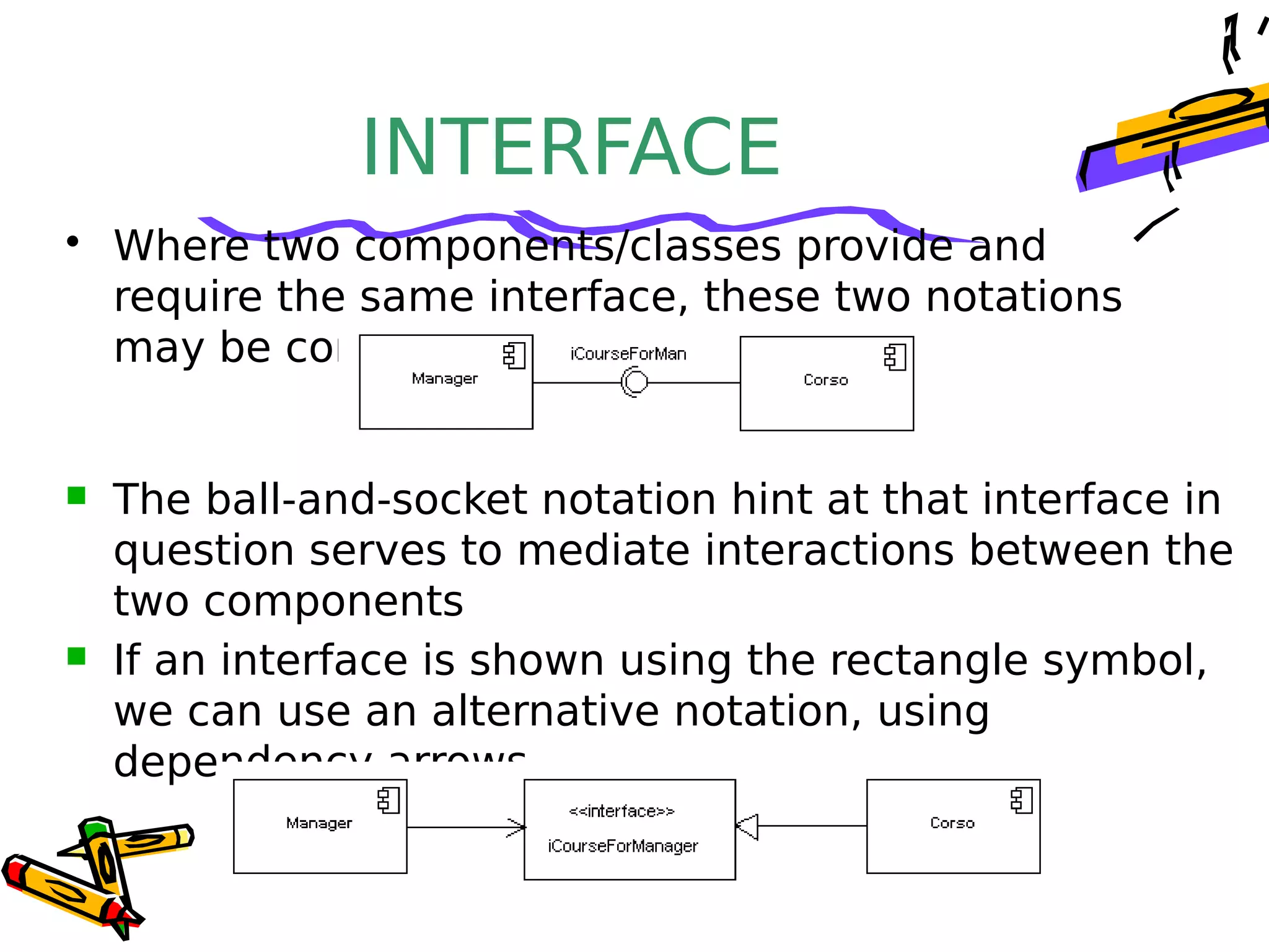
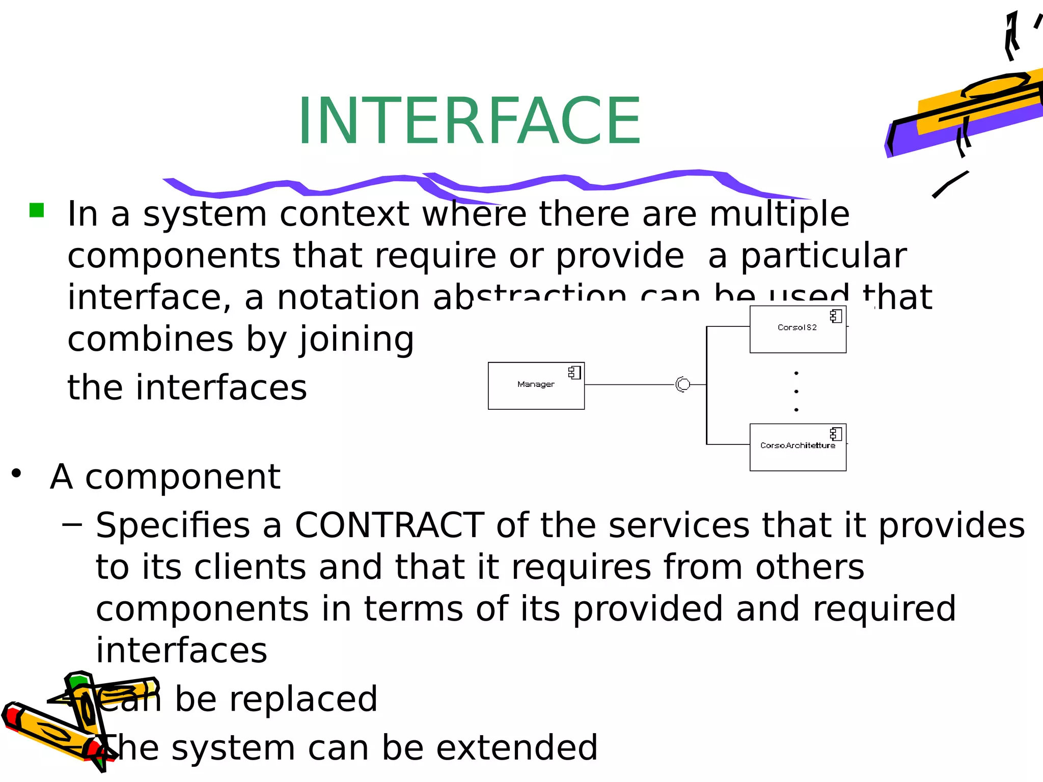
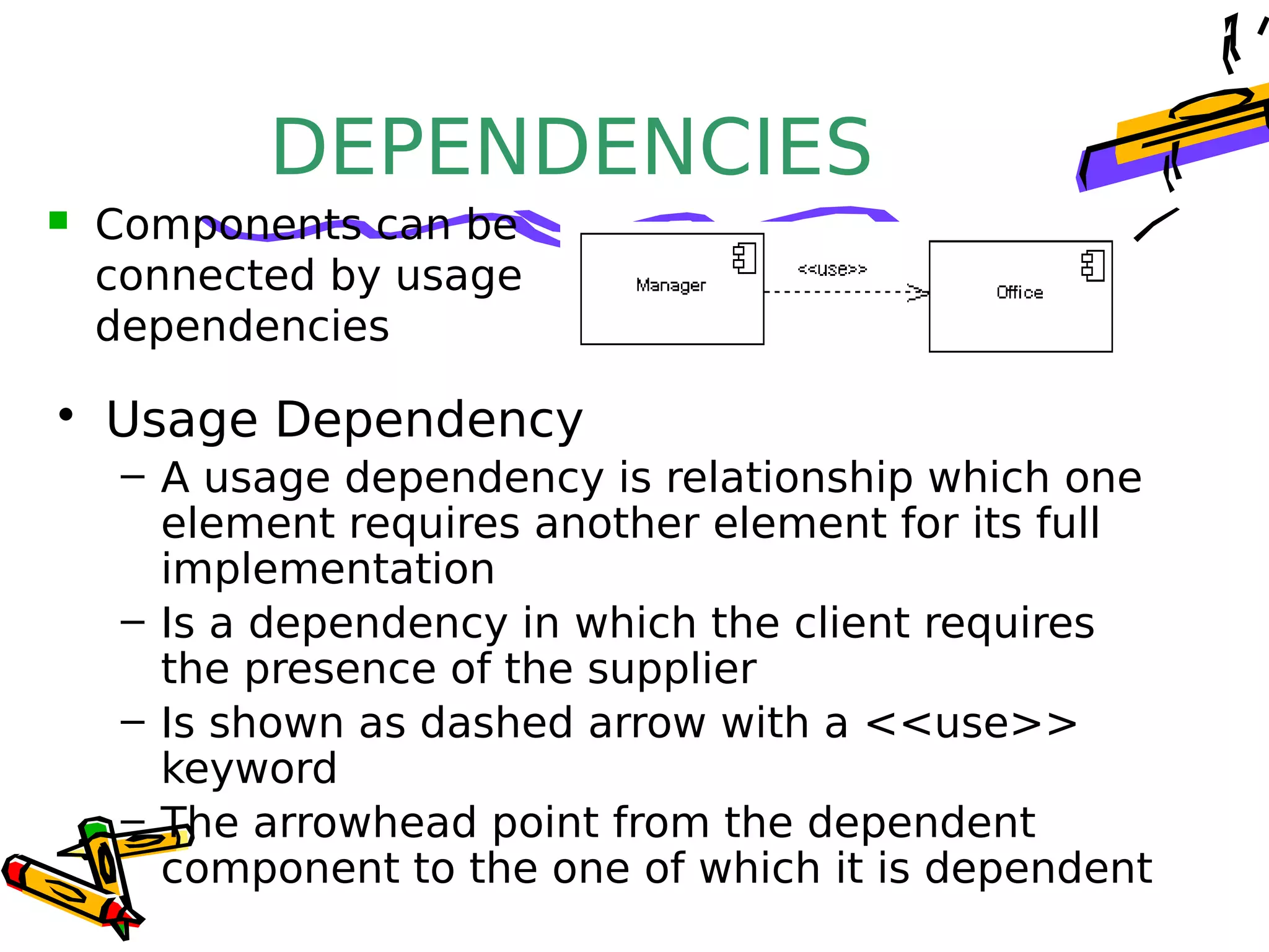
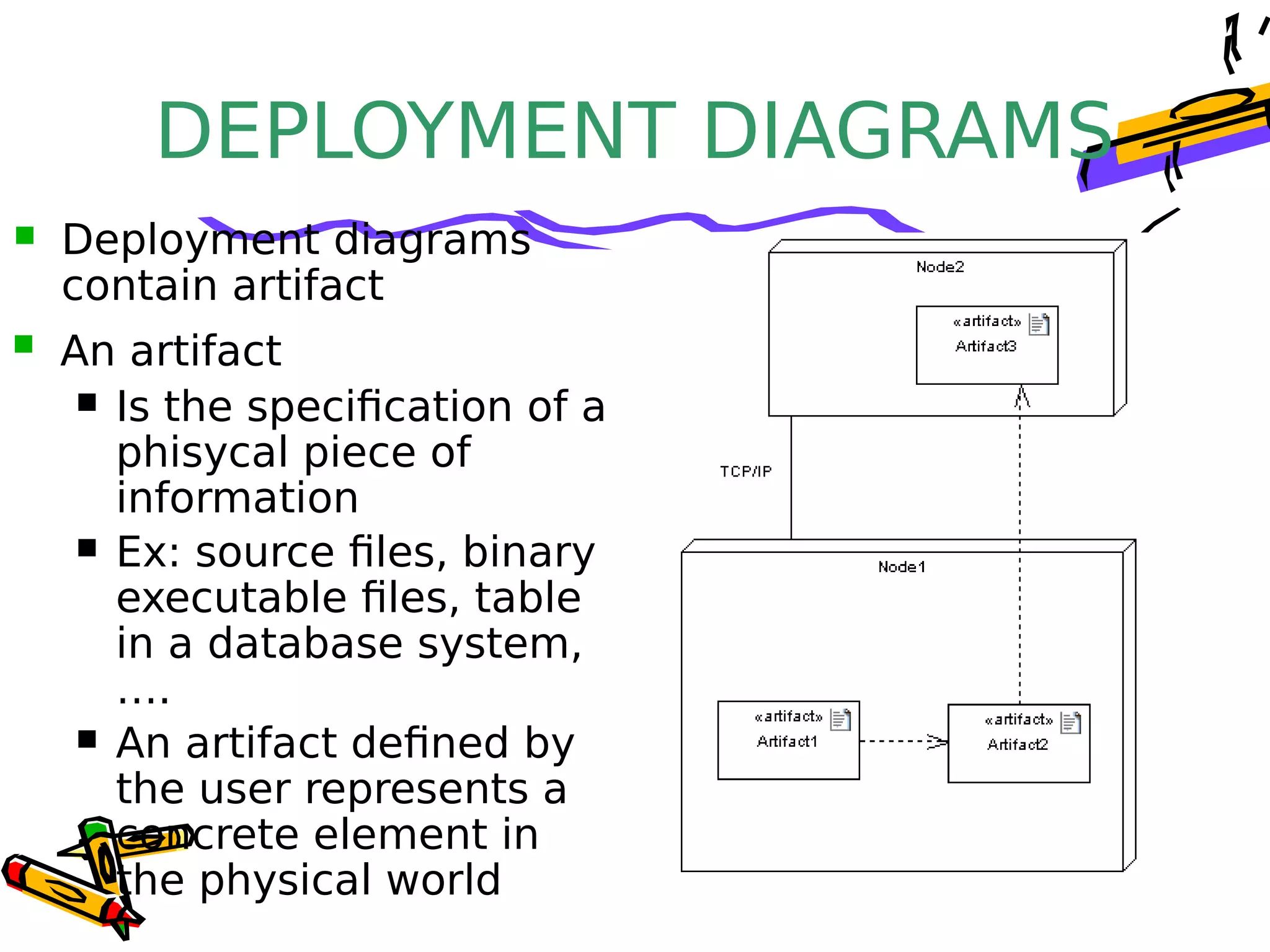
• UML component diagrams describe software
components and their dependencies to each others
– A component is an autonomous unit within a system
– The components can be used to define software systems of
arbitrary size and complexity
– UML component diagrams enable to model the high-level
software components, and the interfaces to those
components
– Important for component-based development (CBD)
– Component and subsystems can be flexibly REUSED and
REPLACED
– A dependency exists between two elements if changes to the
definition of one element may cause changes to the other
– Component Diagrams are often referred to as “wiring
diagrams”
– The wiring of components can be represented on diagrams
Component diagram
INTRODUCTION
An Uml diagram classification:
• Static
– Use case diagram, Class diagram
• Dynamic
– State diagram, Activity diagram, Sequence diagram,
Collaboration diagram
• Implementation
– Component diagram, Deployment diagram
UML components diagrams are
• Implementation diagrams:
describe the different elements required for
implementing a system
INTRODUCTION
Another classification:
• Behavior diagrams
– A type of diagram that depicts behavior of a system
This includes activity, state machine, and use case
diagrams, interaction diagrams
• Interaction diagrams
– A subset of behavior diagrams which emphasize object
interactions.  This includes collaboration, activity,
sequence diagrams
• Structure diagrams
– A type of diagram that depicts the elements of a
specification that are irrespective of time.  This includes
class, composite structure, component, deployment
UML components diagrams are structure
COMPONENT in UML
2.0
• Modular unit with well-defined interfaces
that is replaceable within its environment
• Autonomous unit within a system
– Has one or more provided and required
interfaces
– Its internals are hidden and inaccessible
– A component is encapsulated
– Its dependencies are designed such that
it can be treated as independently as
possible
COMPONENT NOTATION
 A component is shown as a rectangle
with
 A keyword <<component>>
 Optionally, in the right hand corner
a component icon can be
displayed
 A component icon is a rectangle with
two smaller rectangles jutting out from
the left-hand side
 This symbol is a visual stereotype
 The component name Components can be labelled with a stereotype
there are a number of standard stereotypes
ex: <<entity>>, <<subsystem>>
Component ELEMENTS
• A component can have
– Interfaces
An interface represents a declaration of a set of
operations and obligations
– Usage dependencies
A usage dependency is relationship which one element
requires another element for its full implementation
– Ports
Port represents an interaction point between a
component
and its environment
– Connectors
• Connect two components
INTERFACE
 A component defines its behaviour in terms of
provided and required interfaces
 An interface
 Is the definition of a collection of one or more
operations
 Provides only the operations but not the
implementation
 Implementation is normally provided by a class/
component
 In complex systems, the physical implementation is
provided by a group of classes rather than a single
class
INTERFACE
• May be shown using a
rectangle symbol with a
keyword <<interface>>
preceding the name
• For displaying the full
signature, the interface
rectangle can be expanded to
show details Can be
 Provided
 Required
INTERFACE
• A provided interface
– Characterize services that
the component offers to its
environment
– Is modeled using a ball,
labelled with the name,
attached by a solid line to
the component A required interface
 Characterize services that the component expects
from its environment
 Is modeled using a socket, labelled with the name,
attached by a solid line to the component
 In UML 1.x were modeled using a dashed arrow
INTERFACE
• Where two components/classes provide and
require the same interface, these two notations
may be combined
 The ball-and-socket notation hint at that interface in
question serves to mediate interactions between the
two components
 If an interface is shown using the rectangle symbol,
we can use an alternative notation, using
dependency arrows
INTERFACE
• A component
– Specifies a CONTRACT of the services that it provides
to its clients and that it requires from others
components in terms of its provided and required
interfaces
– Can be replaced
– The system can be extended
 In a system context where there are multiple
components that require or provide a particular
interface, a notation abstraction can be used that
combines by joining
the interfaces
DEPENDENCIES
• Usage Dependency
– A usage dependency is relationship which one
element requires another element for its full
implementation
– Is a dependency in which the client requires
the presence of the supplier
– Is shown as dashed arrow with a <<use>>
keyword
– The arrowhead point from the dependent
component to the one of which it is dependent
 Components can be
connected by usage
dependencies
PORT
 Is shown as a small square symbol
 Ports can be named, and the name
is placed near the square symbol
 Is associated with the interfaces
that specify the nature of the
interactions that may occur over a
port
 Specifies a distinct interaction point
 Between that component and its environment
 Between that component and its internal parts
PORT
• Ports can support unidirectional
communication or bi-directional
communication
 If there are multiple
interfaces associated
with a port, these
interfaces may be
listed with the interface
icon, separated by a
commas
PORT
– All interactions of a component with its
environment are achieved through a port
– The internals are fully isolated from the
environment
– This allows such a component to be used in
any context that satisfies the constraints
specified by its ports
– Ports are not defined in UML 1.x
EXTERNAL VIEW
• An external view (or black
box view) shows publicly
visible properties and
operations
 An external view of a component
is by means of interface symbols
sticking out of the component
box
 The interface can be listed in the
compartment of a component box
 A component have an external view and an
internal view
INTERNAL VIEW
• An internal, or white box
view of a component is
where the realizing
classes/components are
nested within the
component shape
 Realization is a relationship between two set
of model elements
 One represents a specification
 The other represent an implementation of
the latter
INTERNAL VIEW
• The internal class that realize the
behavior of a component may be
displayed in an additional
compartment
 Compartments can also be used to
display parts, connectors or
implementation artifacts
 An artifact is the specification of a
phisycal piece of information
INTERNAL VIEW
 Components can be built recursively
ASSEMBLY• Two kinds of connectors:
– Delegation
– Assembly
• ASSEMBLY CONNECTOR
– A connector between 2 components defines that
one component provides the services that
another component requires
– He must only be defined from a required
interface to a provided interface
– An assembly connector is notated by a “ball-
and-socket” connection
This notation allows
for succint grafical
wiring of
components
SEMANTICS
• The semantics for an assembly connector :
– Are that signals travel along an instance of a
connector originating in a required port and
delivered to a provided port
– The interfaces provided and required must be
compatible
– The interface compatibility between provided
and required ports that are connected enables
an existing component in a system to be
replaced
SEMANTICS
– Multiple connections directed from a single required
interface to provided interfaces indicates that the
instance that will handle the signal will be
determined at execution time
DELEGATION
 DELEGATION CONNECTOR
 Links the external contract of a component to
the internal realization
 Represents the forwarding of signals
 He must only be defined between used
interfaces or ports of the same kind
DELEGATION– The target interface must support a signature
compatible with a subset of operations of the source
interface
– A port may delegate to a set of ports on subordinate
components
– The union of the target interfaces must be signature
compatible with the source interface
• Semantics:
– Is a declaration that behaviour that is available on a
component instance is not realized by that component
itself, but by another instance that has compatible
capabilities
– Is used to model the hierarchical decomposition
– Message and signal flow will occur between the
Deployment DiagramDeployment Diagram
DEPLOYMENT
DIAGRAMS
• Deployment diagrams
– Show the physical relationship between
hardware and software in a system
– Hardware elements:
• Computers (clients, servers)
• Embedded processors
• Devices (sensors, peripherals)
– Are used to show the nodes where software
components reside in the run-time system
 There is a strong link between components diagrams
and deployment diagrams
DEPLOYMENT DIAGRAMS
 
 Deployment diagram
 Contains nodes and connections
 A node usually represent a piece of hardware
in the system
 A connection depicts the
communication path
used by the hardware to
communicate
 Usually indicates the
method such as TCP/IP
DEPLOYMENT DIAGRAMS
 An artifact
 Is the specification of a
phisycal piece of
information
 Ex: source files, binary
executable files, table
in a database system,
….
 An artifact defined by
the user represents a
concrete element in
the physical world
 Deployment diagrams
contain artifact
DEPLOYMENT
DIAGRAMS
• An artifact manifest one or more model
elements
• A <<manifestation>> is the concrete physical
of one or more model elements by an artifact
• This model element often is a component A manifestation is
notated as a dashed
line with an open
arrow-head labeled
with the keyword
<<manifest>>
DEPLOYMENT DIAGRAMS

Component diagram

  • 1.
  • 2.
    INTRODUCTION • UML componentdiagrams describe software components and their dependencies to each others – A component is an autonomous unit within a system – The components can be used to define software systems of arbitrary size and complexity – UML component diagrams enable to model the high-level software components, and the interfaces to those components – Important for component-based development (CBD) – Component and subsystems can be flexibly REUSED and REPLACED – A dependency exists between two elements if changes to the definition of one element may cause changes to the other – Component Diagrams are often referred to as “wiring diagrams” – The wiring of components can be represented on diagrams
  • 3.
  • 4.
    INTRODUCTION An Uml diagramclassification: • Static – Use case diagram, Class diagram • Dynamic – State diagram, Activity diagram, Sequence diagram, Collaboration diagram • Implementation – Component diagram, Deployment diagram UML components diagrams are • Implementation diagrams: describe the different elements required for implementing a system
  • 5.
    INTRODUCTION Another classification: • Behaviordiagrams – A type of diagram that depicts behavior of a system This includes activity, state machine, and use case diagrams, interaction diagrams • Interaction diagrams – A subset of behavior diagrams which emphasize object interactions.  This includes collaboration, activity, sequence diagrams • Structure diagrams – A type of diagram that depicts the elements of a specification that are irrespective of time.  This includes class, composite structure, component, deployment UML components diagrams are structure
  • 6.
    COMPONENT in UML 2.0 •Modular unit with well-defined interfaces that is replaceable within its environment • Autonomous unit within a system – Has one or more provided and required interfaces – Its internals are hidden and inaccessible – A component is encapsulated – Its dependencies are designed such that it can be treated as independently as possible
  • 7.
    COMPONENT NOTATION  Acomponent is shown as a rectangle with  A keyword <<component>>  Optionally, in the right hand corner a component icon can be displayed  A component icon is a rectangle with two smaller rectangles jutting out from the left-hand side  This symbol is a visual stereotype  The component name Components can be labelled with a stereotype there are a number of standard stereotypes ex: <<entity>>, <<subsystem>>
  • 8.
    Component ELEMENTS • Acomponent can have – Interfaces An interface represents a declaration of a set of operations and obligations – Usage dependencies A usage dependency is relationship which one element requires another element for its full implementation – Ports Port represents an interaction point between a component and its environment – Connectors • Connect two components
  • 9.
    INTERFACE  A componentdefines its behaviour in terms of provided and required interfaces  An interface  Is the definition of a collection of one or more operations  Provides only the operations but not the implementation  Implementation is normally provided by a class/ component  In complex systems, the physical implementation is provided by a group of classes rather than a single class
  • 10.
    INTERFACE • May beshown using a rectangle symbol with a keyword <<interface>> preceding the name • For displaying the full signature, the interface rectangle can be expanded to show details Can be  Provided  Required
  • 11.
    INTERFACE • A providedinterface – Characterize services that the component offers to its environment – Is modeled using a ball, labelled with the name, attached by a solid line to the component A required interface  Characterize services that the component expects from its environment  Is modeled using a socket, labelled with the name, attached by a solid line to the component  In UML 1.x were modeled using a dashed arrow
  • 12.
    INTERFACE • Where twocomponents/classes provide and require the same interface, these two notations may be combined  The ball-and-socket notation hint at that interface in question serves to mediate interactions between the two components  If an interface is shown using the rectangle symbol, we can use an alternative notation, using dependency arrows
  • 13.
    INTERFACE • A component –Specifies a CONTRACT of the services that it provides to its clients and that it requires from others components in terms of its provided and required interfaces – Can be replaced – The system can be extended  In a system context where there are multiple components that require or provide a particular interface, a notation abstraction can be used that combines by joining the interfaces
  • 14.
    DEPENDENCIES • Usage Dependency –A usage dependency is relationship which one element requires another element for its full implementation – Is a dependency in which the client requires the presence of the supplier – Is shown as dashed arrow with a <<use>> keyword – The arrowhead point from the dependent component to the one of which it is dependent  Components can be connected by usage dependencies
  • 15.
    PORT  Is shownas a small square symbol  Ports can be named, and the name is placed near the square symbol  Is associated with the interfaces that specify the nature of the interactions that may occur over a port  Specifies a distinct interaction point  Between that component and its environment  Between that component and its internal parts
  • 16.
    PORT • Ports cansupport unidirectional communication or bi-directional communication  If there are multiple interfaces associated with a port, these interfaces may be listed with the interface icon, separated by a commas
  • 17.
    PORT – All interactionsof a component with its environment are achieved through a port – The internals are fully isolated from the environment – This allows such a component to be used in any context that satisfies the constraints specified by its ports – Ports are not defined in UML 1.x
  • 18.
    EXTERNAL VIEW • Anexternal view (or black box view) shows publicly visible properties and operations  An external view of a component is by means of interface symbols sticking out of the component box  The interface can be listed in the compartment of a component box  A component have an external view and an internal view
  • 19.
    INTERNAL VIEW • Aninternal, or white box view of a component is where the realizing classes/components are nested within the component shape  Realization is a relationship between two set of model elements  One represents a specification  The other represent an implementation of the latter
  • 20.
    INTERNAL VIEW • Theinternal class that realize the behavior of a component may be displayed in an additional compartment  Compartments can also be used to display parts, connectors or implementation artifacts  An artifact is the specification of a phisycal piece of information
  • 21.
    INTERNAL VIEW  Componentscan be built recursively
  • 22.
    ASSEMBLY• Two kindsof connectors: – Delegation – Assembly • ASSEMBLY CONNECTOR – A connector between 2 components defines that one component provides the services that another component requires – He must only be defined from a required interface to a provided interface – An assembly connector is notated by a “ball- and-socket” connection This notation allows for succint grafical wiring of components
  • 23.
    SEMANTICS • The semanticsfor an assembly connector : – Are that signals travel along an instance of a connector originating in a required port and delivered to a provided port – The interfaces provided and required must be compatible – The interface compatibility between provided and required ports that are connected enables an existing component in a system to be replaced
  • 24.
    SEMANTICS – Multiple connectionsdirected from a single required interface to provided interfaces indicates that the instance that will handle the signal will be determined at execution time
  • 25.
    DELEGATION  DELEGATION CONNECTOR Links the external contract of a component to the internal realization  Represents the forwarding of signals  He must only be defined between used interfaces or ports of the same kind
  • 26.
    DELEGATION– The targetinterface must support a signature compatible with a subset of operations of the source interface – A port may delegate to a set of ports on subordinate components – The union of the target interfaces must be signature compatible with the source interface • Semantics: – Is a declaration that behaviour that is available on a component instance is not realized by that component itself, but by another instance that has compatible capabilities – Is used to model the hierarchical decomposition – Message and signal flow will occur between the
  • 27.
  • 28.
    DEPLOYMENT DIAGRAMS • Deployment diagrams –Show the physical relationship between hardware and software in a system – Hardware elements: • Computers (clients, servers) • Embedded processors • Devices (sensors, peripherals) – Are used to show the nodes where software components reside in the run-time system  There is a strong link between components diagrams and deployment diagrams
  • 29.
    DEPLOYMENT DIAGRAMS    Deploymentdiagram  Contains nodes and connections  A node usually represent a piece of hardware in the system  A connection depicts the communication path used by the hardware to communicate  Usually indicates the method such as TCP/IP
  • 30.
    DEPLOYMENT DIAGRAMS  Anartifact  Is the specification of a phisycal piece of information  Ex: source files, binary executable files, table in a database system, ….  An artifact defined by the user represents a concrete element in the physical world  Deployment diagrams contain artifact
  • 31.
    DEPLOYMENT DIAGRAMS • An artifactmanifest one or more model elements • A <<manifestation>> is the concrete physical of one or more model elements by an artifact • This model element often is a component A manifestation is notated as a dashed line with an open arrow-head labeled with the keyword <<manifest>>
  • 32.