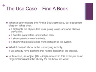
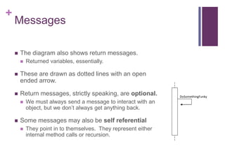
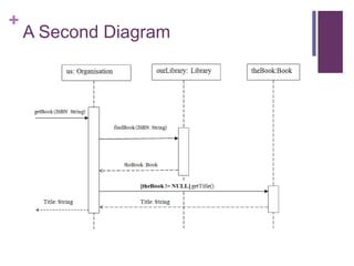
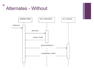
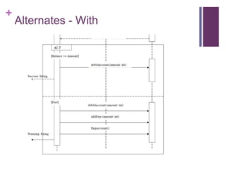
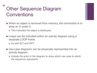
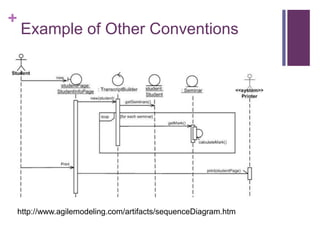
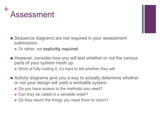
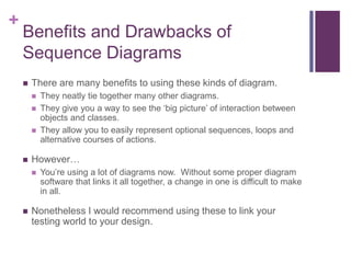
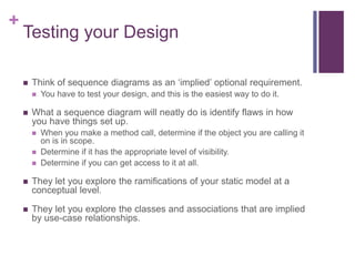
+
Sequence Diagrams
Systems Analysis and Design
Michael Heron
+
Introduction
 We’ve got a lot of tools available to us now to outline parts of a
system.
 The Class Diagram shows us the classes, their relationships, and
the interfaces
 The Use Case Diagram shows us the set of interactions the user
may have with the system.
 The Activity Diagram shows us the underlying logical structure of
activities the user may perform.
 We need though something that allows us to stitch these
together.
 Something that shows us what happens when a user interacts with
our system – what methods are called in what order and with what
information.
+
The Sequence Diagram
 The sequence diagram is the one that does this.
 It ties together processes, activities and object interactions.
 It shows the names of objects, the classes to which they belong,
and the behaviours we’re going to access.
 They are, syntactically, one of the most complicated kind of
UML document.
 It is important to remember that they serve as a ‘refinement’ of other
information elsewhere in your model.
 We use sequence diagrams to define logically the interactions
that a user may have with our system.
 Essentially they are the bit that takes over when someone makes
use of a use-case.
+
A Simple Class Diagram
+
The Use Case – Find A Book
 When a user triggers the Find a Book use case, our sequence
diagram takes over.
 It highlights the objects that we’re going to use, and what classes
they are of.
 It handles parameters, and method calls.
 It shows persistance of methods.
 It shows what gets returned from each part of the system.
 What it doesn’t show is the underlying activity.
 We already have diagrams that handle that part of the process.
 In this case, an object (Us – implemented in this example as an
Organization) asks the library for the book we want.
+
Get Book (ISBN: String)
+
The Lifeline
 One of the key elements of a sequence diagram is the lifeline.
 That’s the box which contains the descriptive label, and the dotted line that descends from it.
 The lifeline represents roles or objects that participate in the sequence being modelled.
 The objects themselves are of secondary importance, only used to show how messages.
 In the box, we use the standard UML naming convention – name of the object and the
name of the class.
 A Library object called ourLibrary, for example.
 Not all lifelines represent named objects. Sometimes they are anonymous or temporary
instances.
 In such cases, we leave the name blank.
 The long thick bars on the lifelines represent persistence.
 The longer they are there, the longer the object must be held in memory.
+
Messages
 Messages are indicated by arrows detailing the message being
sent, and the parameters that go along with it.
 We call them messages, but they are actually method invocations.
 The first message is placed at the top left of the diagram, and
represents the triggering method call.
 This is the very first method that comes into the very first lifeline.
 Each subsequent message is drawn slightly lower down on the
diagram.
 The message indicates a method that is going to be called on
the lifeline to which it points.
+
Messages
 The diagram also shows return messages.
 Returned variables, essentially.
 These are drawn as dotted lines with an open
ended arrow.
 Return messages, strictly speaking, are optional.
 We must always send a message to interact with an
object, but we don’t always get anything back.
 Some messages may also be self referential
 They point in to themselves. They represent either
internal method calls or recursion.
DoSomethingFunky
+
A Second Diagram
+
The Guard
 This second diagram shows an extra element of sequence
notation – the guard.
 This is a conditional expression placed on the transmission of a
message.
 If the condition is not met, then the message will not be transmitted.
 In our diagram, we don’t ask for the title unless we actually
have a book to call the method on.
 Guards must be easily possible to evaluate to true or false
within the context of the diagram.
+
Alternates
 Guards offer a way to place conditions on the sending of a
message, but the usual reality is more complicated.
 If the condition isn’t met, we need to follow an alternate path of
execution.
 To handle this, we use alternates – a ‘box out’ sequence
diagram (known as a frame). This allow us to represent if, if-
else, if-else-if and more complex multiple options.
 Let’s look at a new scenario for this – a bank attempting to
withdraw money from someone’s account.
 If they have it, we give them the money. If they don’t, we give them
the money and then fine them for an unauthorized overdraft.
+
Alternates - Without
+
Alternates - With
+
Alternates
 Alternates represent an either or set of possibilities.
 An if-else
 We can also implement pure ‘if’ relationships by using an OPT
frame.
 This hangs off of the diagram in the same way as an ALT frame.
 Going back to our library example, let’s look at an example of
the user getting a book.
 If it’s there, get the book.
 If the book doesn’t exist, we will instead do an interlibrary loan
request to get it.
+
OPT Frames
+
Other Sequence Diagram
Conventions
 When an object is removed from memory, the convention is to
draw an X under it.
 This indicates the object is destroyed.
 Loops can be indicated within an activity diagram using a
separate LOOP frame.
 As with ALT and OPT.
 Use-case diagrams can be physically represented into an
activity diagram.
 Include the actor in the diagram to show which use case to which
the sequence represents.
+
Example of Other Conventions
http://www.agilemodeling.com/artifacts/sequenceDiagram.htm
+
Assessment
 Sequence diagrams are not required in your assessment
submission.
 Or rather, not explicitly required.
 However, consider how you will test whether or not the various
parts of your system mesh up.
 Short of fully coding it, it’s hard to tell whether they will.
 Activity diagrams give you a way to actually determine whether
or not your design will yield a workable system.
 Do you have access to the methods you need?
 Can they be called in a sensible order?
 Do they return the things you need them to return?
+
Benefits and Drawbacks of
Sequence Diagrams
 There are many benefits to using these kinds of diagram.
 They neatly tie together many other diagrams.
 They give you a way to see the ‘big picture’ of interaction between
objects and classes.
 They allow you to easily represent optional sequences, loops and
alternative courses of actions.
 However…
 You’re using a lot of diagrams now. Without some proper diagram
software that links it all together, a change in one is difficult to make
in all.
 Nonetheless I would recommend using these to link your
testing world to your design.
+
Testing your Design
 Think of sequence diagrams as an ‘implied’ optional requirement.
 You have to test your design, and this is the easiest way to do it.
 What a sequence diagram will neatly do is identify flaws in how
you have things set up.
 When you make a method call, determine if the object you are calling it
on is in scope.
 Determine if it has the appropriate level of visibility.
 Determine if you can get access to it at all.
 They let you explore the ramifications of your static model at a
conceptual level.
 They let you explore the classes and associations that are implied
by use-case relationships.
+
Conclusion
 Sequence diagrams are a powerful tool for stitching together
various diagrams.
 And as a result, they give you an opportunity to explore the
connections between all the various elements.
 They are powerful and offer opportunities for incorporating
more complex flows of execution than many other kinds of
diagrams.
 Through the use of OPT, LOOP and ALT frames.
 While not required for your assessment, they represent your
easiest course of action in terms of validating the design
decisions that you are making.

SAD11 - Sequence Diagrams

  • 1.
    + Sequence Diagrams Systems Analysisand Design Michael Heron
  • 2.
    + Introduction  We’ve gota lot of tools available to us now to outline parts of a system.  The Class Diagram shows us the classes, their relationships, and the interfaces  The Use Case Diagram shows us the set of interactions the user may have with the system.  The Activity Diagram shows us the underlying logical structure of activities the user may perform.  We need though something that allows us to stitch these together.  Something that shows us what happens when a user interacts with our system – what methods are called in what order and with what information.
  • 3.
    + The Sequence Diagram The sequence diagram is the one that does this.  It ties together processes, activities and object interactions.  It shows the names of objects, the classes to which they belong, and the behaviours we’re going to access.  They are, syntactically, one of the most complicated kind of UML document.  It is important to remember that they serve as a ‘refinement’ of other information elsewhere in your model.  We use sequence diagrams to define logically the interactions that a user may have with our system.  Essentially they are the bit that takes over when someone makes use of a use-case.
  • 4.
  • 5.
    + The Use Case– Find A Book  When a user triggers the Find a Book use case, our sequence diagram takes over.  It highlights the objects that we’re going to use, and what classes they are of.  It handles parameters, and method calls.  It shows persistance of methods.  It shows what gets returned from each part of the system.  What it doesn’t show is the underlying activity.  We already have diagrams that handle that part of the process.  In this case, an object (Us – implemented in this example as an Organization) asks the library for the book we want.
  • 6.
  • 7.
    + The Lifeline  Oneof the key elements of a sequence diagram is the lifeline.  That’s the box which contains the descriptive label, and the dotted line that descends from it.  The lifeline represents roles or objects that participate in the sequence being modelled.  The objects themselves are of secondary importance, only used to show how messages.  In the box, we use the standard UML naming convention – name of the object and the name of the class.  A Library object called ourLibrary, for example.  Not all lifelines represent named objects. Sometimes they are anonymous or temporary instances.  In such cases, we leave the name blank.  The long thick bars on the lifelines represent persistence.  The longer they are there, the longer the object must be held in memory.
  • 8.
    + Messages  Messages areindicated by arrows detailing the message being sent, and the parameters that go along with it.  We call them messages, but they are actually method invocations.  The first message is placed at the top left of the diagram, and represents the triggering method call.  This is the very first method that comes into the very first lifeline.  Each subsequent message is drawn slightly lower down on the diagram.  The message indicates a method that is going to be called on the lifeline to which it points.
  • 9.
    + Messages  The diagramalso shows return messages.  Returned variables, essentially.  These are drawn as dotted lines with an open ended arrow.  Return messages, strictly speaking, are optional.  We must always send a message to interact with an object, but we don’t always get anything back.  Some messages may also be self referential  They point in to themselves. They represent either internal method calls or recursion. DoSomethingFunky
  • 10.
  • 11.
    + The Guard  Thissecond diagram shows an extra element of sequence notation – the guard.  This is a conditional expression placed on the transmission of a message.  If the condition is not met, then the message will not be transmitted.  In our diagram, we don’t ask for the title unless we actually have a book to call the method on.  Guards must be easily possible to evaluate to true or false within the context of the diagram.
  • 12.
    + Alternates  Guards offera way to place conditions on the sending of a message, but the usual reality is more complicated.  If the condition isn’t met, we need to follow an alternate path of execution.  To handle this, we use alternates – a ‘box out’ sequence diagram (known as a frame). This allow us to represent if, if- else, if-else-if and more complex multiple options.  Let’s look at a new scenario for this – a bank attempting to withdraw money from someone’s account.  If they have it, we give them the money. If they don’t, we give them the money and then fine them for an unauthorized overdraft.
  • 13.
  • 14.
  • 15.
    + Alternates  Alternates representan either or set of possibilities.  An if-else  We can also implement pure ‘if’ relationships by using an OPT frame.  This hangs off of the diagram in the same way as an ALT frame.  Going back to our library example, let’s look at an example of the user getting a book.  If it’s there, get the book.  If the book doesn’t exist, we will instead do an interlibrary loan request to get it.
  • 16.
  • 17.
    + Other Sequence Diagram Conventions When an object is removed from memory, the convention is to draw an X under it.  This indicates the object is destroyed.  Loops can be indicated within an activity diagram using a separate LOOP frame.  As with ALT and OPT.  Use-case diagrams can be physically represented into an activity diagram.  Include the actor in the diagram to show which use case to which the sequence represents.
  • 18.
    + Example of OtherConventions http://www.agilemodeling.com/artifacts/sequenceDiagram.htm
  • 19.
    + Assessment  Sequence diagramsare not required in your assessment submission.  Or rather, not explicitly required.  However, consider how you will test whether or not the various parts of your system mesh up.  Short of fully coding it, it’s hard to tell whether they will.  Activity diagrams give you a way to actually determine whether or not your design will yield a workable system.  Do you have access to the methods you need?  Can they be called in a sensible order?  Do they return the things you need them to return?
  • 20.
    + Benefits and Drawbacksof Sequence Diagrams  There are many benefits to using these kinds of diagram.  They neatly tie together many other diagrams.  They give you a way to see the ‘big picture’ of interaction between objects and classes.  They allow you to easily represent optional sequences, loops and alternative courses of actions.  However…  You’re using a lot of diagrams now. Without some proper diagram software that links it all together, a change in one is difficult to make in all.  Nonetheless I would recommend using these to link your testing world to your design.
  • 21.
    + Testing your Design Think of sequence diagrams as an ‘implied’ optional requirement.  You have to test your design, and this is the easiest way to do it.  What a sequence diagram will neatly do is identify flaws in how you have things set up.  When you make a method call, determine if the object you are calling it on is in scope.  Determine if it has the appropriate level of visibility.  Determine if you can get access to it at all.  They let you explore the ramifications of your static model at a conceptual level.  They let you explore the classes and associations that are implied by use-case relationships.
  • 22.
    + Conclusion  Sequence diagramsare a powerful tool for stitching together various diagrams.  And as a result, they give you an opportunity to explore the connections between all the various elements.  They are powerful and offer opportunities for incorporating more complex flows of execution than many other kinds of diagrams.  Through the use of OPT, LOOP and ALT frames.  While not required for your assessment, they represent your easiest course of action in terms of validating the design decisions that you are making.