SlideShare a Scribd company logo
1
1 | P a g e
Unit 1 Introduction of electricity
Introduction of electricity
Electricity is a form of energy involving the flow of electrons. All matter is made up
of atoms, which has a center called a nucleus. ... The negative charge of an electron
is equal to the positive charge of a proton, and the number of electrons in an atom is
usually equal to the number of protons.
Who first invented electricity?
Benjamin Franklin
2
2 | P a g e
Building upon Franklin's work, many other scientists studied electricity and began to
understand more about how it works. For example, in 1879, Thomas Edison
invented the electric light bulb and our world has been brighter ever since
How electricity was first discovered?
Italian physicist Alessandro Volta discovered that particular chemical reactions
could produce electricity, and in 1800 he constructed the voltaic pile (an early electric
battery) that produced a steady electric current, and so he was the first person to
create a steady flow of electrical charge
Generation of electricity
 Heat (thermal) energy generated from: fossil fuels; coal. petroleum. natural
gas. solar thermal energy. geothermal energy. nuclear energy.
 Potential energy from falling water in a hydroelectric facility.
 Wind energy.
 Solar electric from solar (photovoltaic) cells.
 Chemical energy from: fuel cells. batteries.
Types of current
There are two types of electric current: direct current (DC) and alternating current (AC).
The electrons in direct current flow in one direction. The current produced by a battery is
direct current. The electrons in alternating current flow in one direction, then in the opposite
direction—over and over again.
Scope of electricity
 For household electric power supply system. eg: TV, Fan Lights etc.
 For industrial power supply system.
 Street light provide.
 Operating different kinds of machine and equipment.
Unit 2 Fundamentals of electric circuits
What is voltage?
Voltage is what makes electric charges move. It is the 'push' that causes charges to move in
a wire or other electrical conductor. ... Voltage is also called, in certain circumstances,
electromotive force (EMF). Voltage is an electrical potential difference, the difference in
electric potential between two places.
It can be expressed in terms of SI base units (m, kg, s, and A) as
V= Potential Energy/ Charge = J/C = kg.m2
/A.s3
It can also be expressed as amperes times ohms (current times resistance, Ohm's law), watts
per ampere (power per unit current, definition of electric power), or joules per coulomb (energy
per unit charge), which is also equivalent to electronvolts per elementary charge:
V=A. Ω = W/A=J/C= eV/e
3
3 | P a g e
What is Current?
Current is a flow of electrical charge carriers, usually electrons or electron-deficient atoms.
... Physicists consider current to flow from relatively positive points to relatively negative
points; this is called conventional current or Franklin current. Electrons, the most common
charge carriers, are negatively charged
What is resistance?
The electrical resistance of an object is a measure of its opposition to the flow of electric
current. The inverse quantity is electrical conductance, and is the ease with which an electric
current passes. Electrical resistance shares some conceptual parallels with the notion of
mechanical friction. The SI unit of electrical resistance is the ohm (Ω), while electrical
conductance is measured in siemens(S).
Ohm's law defines the relationship between thevoltage, current, and resistance in an
electric circuit: i = v/r. The current is directly proportional to the voltage and inversely
proportional to theresistance
The resistance (R) of an object is defined as the ratio of voltage across it (V) to current through it
(I), while the conductance (G) is the inverse:
R=V/I and G=I/V=1/R
Types of Electrical Conductors
 Hard Drawn Copper Conductor. ...
 Cadmium Copper Conductor. ...
 Steel-Cored Copper Conductor (SCC) ...
 Copper Welded Conductor. ...
 Hard-Drawn Aluminium Conductor or All-Aluminum Conductor. ...
 Aluminium Conductor Steel Reinforced. ...
 Smooth Body ACSR Conductor. ...
 Expanded ACSR Conductor.
What Are Two Types of Electrical Circuits?
 Series Circuit. A series circuit has only one path for electricity to flow from
one point to another. ...
 Parallel Circuit. A parallel circuit has multiple paths for electricity to flow from
one point to another. ...
4
4 | P a g e
Measurement of current, voltage, resistance and power
Ampere meter
An ammeter (from Ampere Meter) is a measuring
instrument used to measure the current in a circuit. Electric
currents are measured in amperes (A), hence the name Ampere
meter.
The majority of ammeters are either connected in series with the
circuit carrying the current to be measured (for small fractional
amperes), or have their shunt resistors connected similarly in
series. In either case, the current passes through the meter or
(mostly) through its shunt
Volt meter
A voltmeter is an instrument used for measuring electrical potential difference between two
points in an electric circuit. Analog voltmeters move a pointer across a scale in proportion to
the voltage of the circuit; digital voltmeters give a numerical display of voltage by use of an
analog to digital converter.
Ohmmeter
An ohmmeter is an electrical instrument that measures electrical resistance, the opposition
to an electric current. Micro-ohmmeters (microhmmeter or microohmmeter) make low
resistance measurements. Megohmmeters (also a trademarked device Megger) measure
large values of resistance.
Power Meters/ Watt meter/Energy meter.
A power meter is an electric meter that measures the amount
of electrical energy consumed by residences, businesses or
electrically powered devices. These meters continuously
measure the instantaneous voltage and current to give a
reading of energy used.
5
5 | P a g e
Unit 3 Electrical Energy Transformation
An energy transformation is the change of energy from one form to another. Energy
transformationsoccur everywhere every second of the day. There are many different forms
of energy such as electrical, thermal, nuclear, mechanical, electromagnetic, sound, and
chemical.
6
6 | P a g e
Transformer, its function and application:
A transformer is a static electrical
device that transfers electrical energy
between two or more circuits. A
varying current in one coil of the
transformer produces a
varying magnetic flux, which, in turn,
induces a varying electromotive
force across a second coil wound
around the same core. Electrical
energy can be transferred between the
two coils, without a metallic connection
between the two circuits.
Transformers are used for increasing
or decreasing the alternating voltages
in electric power applications, and for
coupling the stages of signal
processing circuits. Transformer is
used to increase or decrease the
voltage in electrical line. It can increase or decrease the value of capacitor, an inductor or
resistance in an AC circuit. It can thus act as an impedance transferring device.
Isolator, its function and application:
An isolator is a mechanical switching device that,
in the open position, allows for isolation of the input and
output of a device. An isolator is a device used for
isolating a circuit or equipment from a source of power.
In electrical engineering, a disconnector, disconnect
switch or isolator switch is used to ensure that
an electrical circuit is completely de-energized for
service or maintenance. Disconnectors can be operated
either manually or automatically.
It is electronic devise made by using MOSFET (The
Metal-Oxide-Semiconductor Field-Effect Transistor is a
type of field-effect transistor, most commonly fabricated by the controlled oxidation of silicon.
It has an insulated gate, whose voltage determines the conductivity of the device.) or BJT
(A bipolar junction transistor (bipolar transistor or BJT) is a type of transistor that uses both
electron and hole charge carriers. In contrast, unipolar transistors).
Miniature Circuit Breaker
It is on load Device, operated automatically and acts as switch.
A miniature circuit breaker (MCB) automatically switches
off electrical circuit during an abnormal condition of the network
means in overload condition as well as faulty condition.
Nowadays we use an MCB in low voltage electrical network
instead of a fuse. Handling an MCB is electrically safer than a
fuse.
Figure 1 Ideal transformer and induction law
7
7 | P a g e
Electric poles, its function and application
Utility poles are commonly used to carry two types of electric
power lines: distribution lines (or "feeders") and
subtransmission lines. Subtransmission lines carry higher
voltage power from regional substations to local substations.
The distance between two OHE (Over Head Equipment) Poles
is usually 50 meters. It should not exceed 54 meters. The wire
is at about 5.50m from the rail level.
Utility poles are commonly used to carry two types of
electric power lines:[2]
distribution lines (or "feeders")
and subtransmission lines. Distribution lines carry power from
local substations to customers. They generally carry voltages
from 4.6 to 33 kilovolts (kV) for distances up to 30 miles,
Electrical safety tips:
 Never put fingers or other objects in an outlet.
 Keep metal objects out of toasters.
 Never use anything with a cord or plug around water.
 Never pull a plug out by its cord.
 Stay away from substations and power lines.
 Don't climb on power poles.
 Never fly kites near power lines.
 Don't touch someone who's been electrocuted! ...
 Know your Electrical Code. ...
 Always use GFCIs (ground-fault circuit interrupter) in damp or wet work areas. ...
 Inspect & maintain your electrical tools. ...
 Follow proper lockout/tagout procedures. ...
 Wear the right safety gear. ...
 Choose the right ladder. ...
 Avoid power lines.
Unit 4 Measuring Instruments and Protecting Devices
Foot and meter/scale (Linear measuring instruments)
A tape measure or measuring tape is a flexible ruler and used to measure
distance. It consists of a ribbon of cloth, plastic, fiber glass, or metal strip
with linear-measurement markings. It is a common measuring too.
It is use to measure linear length in different unit such as meter and feet. Inch is small unit of
feet similarly millimeter is small unit of meter.
8
8 | P a g e
Vernier caliper/caliper
A vernier scale is a visual aid to take an accurate measurement reading between two graduation
markings on a linear scale by using mechanical interpolation; thereby increasing resolution and
reducing measurement uncertainty by using Vernier acuity to reduce human estimation error.
Purpose: Measuring more precisely than could be done unaided when reading a uniformly divided
straight or circular measurement scale
Standard wire gauge
British Standard Wire Gauge is a set of wire sizes given
by BS 3737:1964 (now withdrawn), and is generally abbreviated to
SWG. It is also known as: Imperial Wire Gauge or British
Standard Gauge. Use of SWG sizes has fallen greatly in
popularity, but is still used as a measure of thickness in guitar
strings and some electrical wire. Cross sectional area in
square millimeters is now the more usual size measurement
for wires used in electrical installation cables. The current
British Standard for metallic materials such as wire and sheet
is BS 6722:1986, which is a solely metric standard.
feeler gauge
A feeler gauge is a tool used to measure gap widths. Feeler
gauges are mostly used in engineering to measure the clearance
between two parts.[1]
They consist of a number of small lengths of steel of different thicknesses with measurements
marked on each piece. They are flexible enough that, even if they are all on the same hinge,
several can be stacked together to gauge intermediate values
What is the measuring range for radius gauge?
A radius gauge, also known as a fillet gauge, is a tool used to measure the radiusof an
object. Radius gauges require a bright light behind the object to bemeasured. The gauge is
placed against the edge to be checked and any light leakage between the blade and edge
indicates a mismatch that requires correction.
Micrometer
9
9 | P a g e
A gauge that measures small distances or thicknesses between its two faces, one of which
can be moved away from or towards the other by turning a screw with a fine thread.
Miniature Circuit breaker (MCB)
A circuit breaker is an automatically operated electrical switch designed to protect an electrical
circuit from damage caused by excess current from an overload or short circuit. Its basic function
is to interrupt current flow after a fault is detected. Unlike a fuse, which operates once and then
must be replaced, a circuit breaker can be reset (either manually or automatically) to resume
normal operation.
What are the different sources of electric power?
The three major categories of energy for electricity generation are fossil fuels (coal,natural gas,
and petroleum), nuclear energy, and renewable energy sources. Most electricity is generated
with steam turbines using fossil fuels, nuclear, biomass, geothermal, and solar thermal energy.
Direct current (DC) is the unidirectional flow of an electric charge. A battery is a prime
example.... electricity and water as byproducts) also produce only DC. Light aircraft electrical
systems are typically 12 V or 24 V DC similar to automobiles.
Alternating current (AC) is an electric current which periodically reverses direction, in contrast to
... High-voltage direct-current (HVDC) electric power transmission systems have become more
viable as technology has provided efficient means ...
The single-phase power supply has one distinct wave cycle whereas; three
phase has three distinct wave cycles. Single phase requires the single wire to connect the circuit
whereas; 3-phase needs 3-wires. The voltage of the single phase is 230V, whereas three
phase voltage is 415V.
single-phase power three phase power
1. Mostly use in Domestic Propose. 1. Mostly use in Industries, factory
10
10 | P a g e
What is a power inverter?
An inverter is a critical piece of
equipment in any PV system.
The inverter takes DC power,
either from your solar panels or
batteries, and turns it into AC power,
ready and usable for your
household appliances. Grid-tie and
off-grid solar systems use different
types of inverters.
The Solar Inverter is an essential
device in any solar power system.
Its basic function of the inverter is
to change the variable Direct
Current output of the solar panels
into Alternating Current. ... The
primary function of an inverter is to
convert Direct Current (DC) power
into standard, Alternating Current (AC).
Solar power is the conversion of energy from sunlight into electricity, either directly
using photovoltaics (PV), indirectly using concentrated solar power, or a combination.
Concentrated solar power systems use lenses or mirrors and tracking systems to focus a large
area of sunlight into a small beam. Photovoltaic cells convert light into an electric current using
the photovoltaic effect. A solar cell, or photovoltaic cell (PV), is a device that converts light into
electric current using the photovoltaic effect.
Earthing System
Introduction of earthing
In an electrical installation, an earthling system or grounding system connects specific parts
of that installation with the Earth's conductive surface for safety and functional purposes. The point
of reference is the Earth's conductive surface. The choice of earthing system can affect
the safety and electromagnetic compatibility of the installation. Regulations for earthing systems
vary considerably
11
11 | P a g e
What is the function of earthing?
In an electrical installation, an earthing system or grounding system connects specific parts of
that installation with the Earth's conductive surface for safety and functional purposes. The point
of reference is the Earth's conductive surface. Earthing is used to protect you from an electric
shock. It does this by providing a path (a protective conductor) for a fault current to flow to earth.
It also causes the protective device (either a circuit-breaker or fuse) to switch off the electric
current to the circuit that has the fault.
Objectives of electrical earthing
Protective earthing
An earth ground connection of the exposed conductive parts of electrical equipment helps protect
from electric shock by keeping the exposed conductive surface of connected devices close to earth
potential, when a failure of electrical insulation occurs. When a fault occurs, current flows from the
power system to earth.
Functional earthing
A functional earth connection serves a purpose other than electrical safety, and may carry current
as part of normal operation.[1] For example, in a single-wire earth return power distribution system,
the earth forms one conductor of the circuit and carries all the load current. Other examples of
devices that use functional earth connections include surge
An electric shock is a dangerous and painful physiological effect caused by the passing of
an electric current through the body of a human or animal. ... An electric shock is a dangerous and
painful physiological effect caused by the passing of an electric current through the body of a
human or animal.
Effects of electric shock on human body
Nerves are tissue
that offers very little
resistance to the
passage of
an electric
current. When
nerves are affected
by an electric
shock, the
consequences
include pain,
tingling, numbness,
weakness or
difficulty moving a
limb.
These effects may
clear up with time
or be permanent.
12
12 | P a g e
In this article we will go to give you a brief overview of different types
of grounding systems and Methods of Earthing.
1. TT Earthing system:-
This system normally used for consumer
power supply. No earthing system
provided by power distributor. The owner
must install the earthing protection by
their own connection to the earth. They
must installing a suitable electrode and
safe arrangement for which they are
responsibility to their installation.
The neutral and earthing conductor must be separately through the installation because power distributor
only provide the supply neutral or protective conductor for the connection to consumer.
2. IT Earthing system:-
This system is similar with TT system but totally
different in earthing supply. The distributor system
not have any connections to earth or it have only a
high impedance connection. It mean the usual
protection is not effective for this system. This type is
not for consumer power supply. It special for power
distributor such as substation or generator area.
3. TN-S Earthing system:-
This system has the neutral of power
supply with connection of earth only at one
point to the source. the consumer’s
earthing terminal is usually connected to
the metallic Armour of the distributor’s
cable into the High voltage and low Voltage
transformer.
13
13 | P a g e
4. TN-C-S Earthing system:-
This system has the supply neutral
conductor of a distribution main
connected with earth at source as
protective multiple earthing. The
supply distributor neutral conductor is
also used to return earth fault currents
from the consumer installation back to
the source with a safely manner.
The power supply distributor will
provide a consumer’s earthing terminal
which is linked to the incoming neutral
conductor. This combined earth and neutral system called the protective and neutral
conductor or the combined neutral and earth conductor.
5. TN-C Earthing system:-
This system is not familiar or
unusual for earthing system. It a
combined neutral conductor fulfills
the functions of both a PE and an N
conductor. The neutral conductor
is the sheath of a cable and
therefore is concentric with (totally
surrounds) the phase conductor.
Earthing can be done in many ways. The various methods employed in earthing, (in house
wiring or factory and other connected electrical equipment and machines) are discussed as
follows.
14
14 | P a g e
Now we will brief Methods of Earthing
1. Plate Earthing:-
In plate earthing system, a plate made up of either
copper with dimensions 60cm * 60cm * 3.18mm or
galvanized iron of dimensions 60cm * 60cm * 6.35
mm is buried vertical in the earth pit, which should
not be less than 3meter from the ground level.
2. Pipe Earthing:-
A galvanized steel and a perforated pipe of approved
length and diameter is placed vertically in a wet soil in
this kind of system of earthing. It is the most common
system of earthing.
3. Earthing through the Water man:-
In this method of earthing, the waterman (Galvanized GI) pipes are used for earthing
purpose. Make sure to check the resistance of GI pipes and use earthing clamps to minimize
the resistance for proper earthing connection.
15
15 | P a g e
5. Strip or Wire Earthing:-
In this method of earthing, strip electrodes of cross-
section not less than 25mm * 1.6mm is buried in a
horizontal trenches of a minimum depth of 0.5meter.
If copper with a cross-section of 25mm * 4mm is used
and a dimension of 3.0mm. if it’s a galvanized iron or
steel.
Unit 8 Electric Wiring Procedure
What is electrical layout plan?
Electrical Plan. Electrical plan is “a
preplan of electrical design on a
paper before the physical
installation of electrical appliances
and machines in real time”. This
electrical plan consists of several
standard symbols
of electrical appliances and
machines and their
interconnection.
16
16 | P a g e
Types of Electrical Wiring Systems
The state electricity board provides the electric supply up to the outside the consumer’s
premises. The consumer has to take the connection from that point to the main switchboard
at home.
From the main switchboard, various types of electrical loads such as fans, lights, room
coolers, and refrigerators are connected through the wires.There are different types of
wirings used for connecting the loads to the mains which can be used for house electrical
wiring as well as industrial electrical wiring. Some of these are discussed below.
Cleat Wiring
In this, porcelain, wood or
plastic cleats are fixed to walls
or ceilings at regular intervals,
i.e., 0.6 m between each cleat.
PVC insulated cables are taken
through the holes of each cleat
and hence cleat support and
holds wire.This is an
inexpensive method of wiring and is used for temporary installations. Therefore, it is not
suitable for home electrical wiring and also it is an outdated method.
Casing and Capping Wiring
In this cable is run
through a wood
casing having
grooves. The wood
casing is prepared
in such a way that it
is of a required
fixed length with
parallel grooves
that accommodates
the cables. The
wooden casing is
fixed to the walls or
ceiling with screws.
After placing the cables inside the grooves of casing, a wooden cap with grooves is placed on
it to cover the cables. This is also a cheap wiring system, but there is a high risk of fire in case
of short circuits.
17
17 | P a g e
Batten Wiring
In this, insulated wires are run
through the straight teak
wooden battens. The wooden
battens are fixed on the ceilings
or walls by plugs and screws.
The cables are fitted onto the
battens by using tinned brass
link clips.
These clips are fixed to the
battens with rust-resistant nails.
This wiring installation is simple
and cheap as compared to other
electrical wiring systems also takes less time to install. These are mainly used for indoor
installations.
Conduit Wiring
In this wiring, PVC cables are taken
through either PVC conduit pipes or
through steel conduit pipes. This
conduit wiring can be either surface
conduit wiring or concealed conduit
wiring.
If the conduit pipes are run on surface
of the walls and ceilings, it is called a
surface conduit wiring. If the conduits
are run inside the surface of the walls
and ceilings and are covered with
plastering, it is called as concealed
conduit wiring.
Surface conduit wiring is used in industries to connect the heavy motors. On the other hand,
concealed wiring is the most popular and common method of wiring the residential
buildings. The conduit wiring is the safest method of wiring and also looks beautiful
(concealed conduit wiring).
Types of Drawings
Electrical drawings plays an important role in electrical installation works that they convey
information about connection of various devices and equipments with mains. The
information on drawings provides the complete design or plan of electrical installation and
also helps to assemble the various equipments.
Some of the electrical wiring diagrams are discussed below. Before knowing about these
diagrams, first one must aware and have idea about various symbols used while preparing
drawing and also for understanding the wiring connections. Check out various electrical
wiring symbols .
18
18 | P a g e
Block Diagram
It is a functional drawing which shows
and describes the main operating
principles of the equipment or
devices. It consists of principle
functions or parts represented by
blocks and are connected through
lines that show the relationship
between the blocks.This diagram is
usually drawn before implementing a
circuit diagram. It will not give any
detailed information about the system
and also leaves the information about
smaller components. And hence, most
technicians have limited interest
about this diagram.
Circuit Drawing (Diagram)
In this, electrical circuit is graphically represented in a simplified manner. It includes the
position information (in cm or m or mm) of various elements like light fixtures, receptacle
boxes, junction boxes, ceiling fans, etc.
Line Diagram
It is a simplified notation of an electrical system, also called as one-line diagram or single
line diagram. It is similar to the block diagram except that various electrical elements such as
transformers, switches, lights, fans, circuit breakers, and motors are represented by standard
schematic symbols.
19
19 | P a g e
It consists of symbols to represent the components and lines to represent the wires or
conductors which connects the components together. The line diagram is actually derived
from the block diagram. It doesn’t give any layout of the parts and their detail wiring
information of the components. However, one can do wiring by following the information
given in this diagram. These diagrams are usually intended to illustrate the working of an
electric circuit.
Wiring Diagram
The electrical wiring diagram is a pictorial representation of the circuit which shows the
wiring between the parts or elements or equipments. It gives detailed information about
wiring such that one can get an idea of making connection between the devices. It includes
relative position, arrangement of the devices and also terminals on the devices. It shows
power supplies and earth connections, control and signal functions (with simplified shapes),
termination of
unused
contacts and
leads,
interconnection
via plugs,
blocks, sockets,
terminal posts,
lead-through,
etc.
20
20 | P a g e
Wiring Schedule
It is a list of cables or wires used
in the installation with its
reference number, length, type
and the amount of insulation
stripping required for soldering
the cable. It gives the raceways of
the wire and also starting and
termination points. In some
complex equipment, wiring table
gives the interconnection of the
equipments (such as motors and heaters) with starting and finishing reference points. It also
includes the wire identification markings, wire colors, size and so on.
Parts List
Although it is not a drawing,
parts list is an integral part of
drawing which defines the
various symbols and parts used
in other drawings such as
wiring diagram, line diagram,
and block diagram. It gives the
information of circuit component types with related to their reference numbers. This list is
useful for identifying, locate and cross refer the actual component labeled or given in other
electrical drawings in order to ensure the choice of appropriate parts before doing the
electrical wiring.
Wiring Preparation
As we are discussing the sequence of steps in wiring like understanding the safety, knowing
types of wiring systems, understanding the difference among various electrical drawings and
symbols, the next step of electrical wiring process is the preparation of wires or cables and
electrical tools.
Types of Electrical Wiring
We know that electrical circuit is a closed path through which electricity flows from
phase or hot wire to the device or apparatus and then back the source though
neutral wire.
Along the way, the electricity path may consist of fixtures, switches, receptacles,
junction boxes, etc. So the wiring may be routed through these elements before
actually making connections with apparatus or device.
Majorly, the wiring is divided into two types, namely parallel wiring and series wiring
depending on the way the devices are powered or connected to the supply.
21
21 | P a g e
In parallel wiring, several devices on the installation are powered on a single circuit.
It is the most accepted wiring in homes and industries, in which devices are
connected in parallel with the supply source as shown in figure.
In this, both phase (or hot) and neutral cables are routed through the electrical boxes
(junction boxes) from which individual receptacles, fixtures, and devices are
branched.
The series wiring is the rarely used wiring in which hot wire is routed through the
several devices and then last device terminal is connected to the neutral wire. It is
like an old Christmas lights or serial lights wiring in which one light burnout leads to
the shutdown of the entire network.
22
22 | P a g e
Examples of Electrical Wiring
For a better understanding of the wiring concept, here we are giving some examples
of the wiring circuits which we are dealing daily in our homes.
Single bulb controlled by a one way switch
In this, hot wire is connected to the one terminal of the switch and other terminal of
the switch is connected to the bulb positive terminal, then bulb negative terminal is
connected to the neutral wire as shown in figure.
23
23 | P a g e
Two blubs are controlled by a one way switch
In this, two bulbs are connected in parallel with the supply wires (phase and neutrals)
which are routed by single one-way switch as shown in figure.
Single blub (or any other load) controlled by two way switches
This wiring is also called as staircase wiring in which a light lamp is controlled from
two sources by using two two-way switches. This type of wiring is used in bed rooms
to switch ON/OFF the lamp from two sources (at the bed side and at switchboard).
The connection of switches with the lamp is shown below.
24
24 | P a g e
Godown Wiring
This type wiring is used in big godowns, long passages, warehouses and tunnel like
structures having many rooms or portions. It follows the linear sequence for
switching the lights from one end to the other.
When a person leaves from one room and enters next, by turning the light switch
makes earlier lamp switched OFF while present room is switched ON. It turns OFF
the lamp while switching another. The schematic wiring diagram for godown wiring is
shown in below.
25
25 | P a g e
Fluorescent lamp controlled by a one-way switch
The switching of fluorescent lamp with single one-way switch through ballast and
capacitor is shown in below figure. In this, phase wire is connected to the one end of
the switch and another end of the switch is connected to the choke (or ballast). One
electrode of the lamp is connected to the choke and other to neutral terminal as
shown in figure.
Socket outlet wiring
The outlet holds a plug and passes the current through it when the power is routed to
the socket through a switch. The single socket connection and radial socket
connection are shown in below figure.
26
26 | P a g e
Control switch board wiring
The schematic diagram for a control switch board is shown in below figure in which
ceiling fan, fluorescent lamp and light bulb are controlled by appropriate switches.
GROUND FLOOR PLAN FIRST FLOOR PLAN SECOND FLOOR PLAN
TYPICAL LAYOUT OF SDB
(NOT TO SCALE)
S P M C B
D P M C C B
LEGEND
FIXING POSITIONSYMBOL
Single pole switch
Sub distribution board
DESCRIPTION
Tube light
Telephone outlet
5 -15 APower socket
Television outlet
Bell
Wall Light
Main distribution bar
1800 mm Above FFL
1300 mm Above FFL
250 mm Above FFL
Mirror light (wall)
power circuit line
light circuit line n no.s of 3/18 cu wire
2 x 3/18 + 1 x 3/22 cu wire
LED panel light(9 w)
foot light
compact flurescent lamp( 2 x 20
w)
32 A TPN KWH METER
(SUPPLIED BY NEA)
40 A TPN MCCB
4X16+ 1X6 -E
SP&N
32A
E
MAIN CONTROL PANEL
1X10sq.mmCUCABLE
sq. mm CU CABLE
CHANGEOVER
4X16 + 1X6 -E sq. mm CU CABLE
FOR DG/NORMAL
SP&N
20A
FUTURE
SECOND
SP&N
32A
SP&N
32A
THIRD
E
4X16+ 1X6 -E
sq. mm CU CABLE
SP&N
32A
E
SPARE
SP&N
32A
FIRSTGROUND
12345
KWH
20-40
kWH
12345
KWH
20-40
kWH
BACKUP DIESEL GENRATOR
(20 kVA, 400 V, 50 Hz, 0.8 pf)
6A 16A 16A
PC2
(2x6+1x2.5) sq. mm; Copper
single core PVC cable drawn
inside 25 mm ∅ conduit
PC1
from Main
Control Panel
6A
LC4
6A
LC3
16A
PC3 SPR
16A
PC9
(2x6+1x2.5) sq. mm; Copper
single core PVC cable drawn
inside 25 mm ∅ conduit
from Main
Control Panel
SPR
6A
LC12
6A
LC10
16A
PC10
6A
LC13 PC11
TOEQUIPMENT
150 600
900
SURROUNDED BY SALT
150
150
SALT
SALT
600 X 600 X 3.14 MM
CHARCOAL
600150
900
10 MM SQ. COPPER CONDUCTOR IN GI PIPE
150
200
125
500
WIRE MESH
32 MM GI PIPE FOR WATERING
FUNNEL
C.I. COVER WITH FRAME
0.00 LEVEL
P.C.C.
COPPER PLATE
AND CHARCOAL
E.. GROUND STATION
6A
LC5
16A 6A
LC11 SPR
6A
(2x6+1x2.5) sq. mm; Copper
single core PVC cable drawn
inside 25 mm ∅ conduit
from Main
Control Panel
6A
LC17
6A
LC15
6A
LC18
6A
LC16
16A
PC17SPR SPR
6A
(2x6+1x2.5) sq. mm; Copper
single core PVC cable drawn
inside 25 mm ∅ conduit
from Main
Control Panel
6A
LC19 SPR
16A
PC4
6A
LC9
16A
PC8
16A
PC7
16A 16A 16A 16A
Dome Light, 1 X 15w CFL
PC12 PC13
16A16A
PC5
16A
SPR
6A6A
LC2
6A
LC1
GROUND FLOOR PLAN FIRST FLOOR PLAN SECOND FLOOR PLAN
TOP FLOOR PLAN
Light Points Layout
Light Points LayoutLight Points Layout
Light Points Layout
POWER CIRCUIT LAYOUT POWER CIRCUIT LAYOUT POWER CIRCUIT LAYOUT
6A
LC6
6A
SPR
6A
LC8
Car Porch
Toilet
U
P
2 3 41
B
C
2 3 41
B
C
U
P
A A
Bed Room
Bed Room
Bed Room
Bed Room
2 3 41
B
C
2 3 41
B
C
U
P
A A
Bed Room
Bed Room
6"
6"
8"
2 3 41
B
C
2 3 41
B
C
A A
13'-3"13'-11"
W1
W4
W1
W1
W2
W3
W4
W1
W1
W1
W3
W1
W1
W4
W1
W1
W2 W2
D1
D1
D1
D1
D1
D1
D1
D1
D2
D2 D2
D1
MD
D1
28'-2"
12'-9" 12'-5" 11'-9"
38'-1"
12'-9" 12'-5" 11'-9"
40'-9"
13'-3"13'-11"
28'-2"
13'-3"13'-11"
28'-2"
12'-9" 12'-5" 11'-9"
40'-9"
12'-9" 12'-5" 11'-9"
41'-3"
13'-3"13'-11"
28'-2"
13'-3"13'-11"
28'-2"
37'-11"
12'-9" 12'-5" 11'-9" 3'-10"
41'-3"
12'-9" 12'-5" 11'-9"
Bed Room
12'-0"X 12'-0"
Bed Room
12''0"X 12'-0"
Store Room
7'-8"X 3'-5"
Kitchen
11'-0"X 7'-8"
8'-0"X 4'-10"'
Living /Dinning Room
21'-6"X 15'-1"
12'-10"X 12'-8"
13'-6"X 12'-8"
Family Room
13'-7"X 11'-5"
Toilet
8'-0"X 5'-8"'
12'-10"X 12'-8"13'-11"X 12'-9"
13'-2"X 11'-5"
13'-6"X 12'-8"
W1
13'-3"13'-11"
28'-10"
DW1
A
A
A
A
A
A
Terrace
W4
W4
DW2
9"
Balcony DW2
VoidVoid
6'-1"
6'-5"
Car Porch
Toilet
U
P
2 3 41
B
C
2 3 41
B
C
U
P
A A
Bed Room
Bed Room
Bed Room
Bed Room
2 3 41
B
C
2 3 41
B
C
U
P
A A
Bed Room
Bed Room
6"
6"
8"
2 3 41
B
C
2 3 41
B
C
A A
X
X
13'-3"13'-11"
W1
W4
W1
W1
W2
W3
W1
W1
W1
W3
W1
W1
W4
W1
W1
W2 W2
D1
D1
D1
D1
D1
D1
D1
D1
D2
D2 D2
D1
MD
D1
28'-2"
12'-9" 12'-5" 11'-9"
38'-1"
12'-9" 12'-5" 11'-9"
40'-9"
13'-3"13'-11"
28'-2"
13'-3"13'-11"
28'-2"
12'-9" 12'-5" 11'-9"
40'-9"
12'-9" 12'-5" 11'-9" 2'-7"
41'-3"
13'-3"13'-11"
28'-2"
13'-3"13'-11"
28'-2"
37'-11"
12'-9" 12'-5" 11'-9" 3'-10"
41'-3"
12'-9" 12'-5" 11'-9"
Bed Room
12'-0"X 12'-0"
Bed Room
12''0"X 12'-0"
Store Room
7'-8"X 3'-5"
Kitchen
11'-0"X 7'-8"
8'-0"X 4'-10"'
Living /Dinning Room
21'-6"X 15'-1"
12'-10"X 12'-8"
13'-6"X 12'-8"
Family Room
13'-7"X 11'-5"
Toilet
8'-0"X 5'-8"'
12'-10"X 12'-8"13'-11"X 12'-9"
13'-2"X 11'-5"
13'-6"X 12'-8"
W1
13'-3"13'-11"
28'-10"
38'-5"
28'-2"
26'-2" 3'-7"
16'-7"
DW1
A
A
A
A
A
A
Terrace
Terrace Below Terrace
W4
W4
DW2
Balcony DW2
VoidVoid
6'-1"
6'-5"
3'
LC # 1
LC # 3
LC # 6
LC # 4
LC # 2
LC # 5
LC # 8
LC # 9
LC # 7
LC # 10
LC # 13 LC # 15
LC # 16
LC # 14
LC # 17
LC # 18
LC # 11
6A
LC7
6A
LC14
6A
LC6
GROUND FLOOR PLAN
Car Porch
Toilet
U
P
2 3 41
B
C
2 3 41
B
C
A A
13'-3"13'-11"
W1
W4
W1
W1
W2
W3
W4
D1
D2
D2
MD
D1
28'-2"
12'-9" 12'-5" 11'-9"
38'-1"
12'-9" 12'-5" 11'-9"
40'-9"
13'-3"13'-11"
28'-2"
Bed Room
12'-0"X 12'-0"
Bed Room
12''0"X 12'-0"
Store Room
7'-8"X 3'-5"
Kitchen
11'-0"X 7'-8"
8'-0"X 4'-10"'
Living /Dinning Room
21'-6"X 15'-1"
A
A
W4
Void
TOEQUIPMENT
150 600
900
SURROUNDED BY SALT
150
150
SALT
SALT
600 X 600 X 3.14 MM
CHARCOAL
600150
900
10 MM SQ. COPPER CONDUCTOR IN GI PIPE
150
200
125
500
WIRE MESH
32 MM GI PIPE FOR WATERING
FUNNEL
C.I. COVER WITH FRAME
0.00 LEVEL
P.C.C.
COPPER PLATE
AND CHARCOAL
32 A TPN KWH METER
(SUPPLIED BY NEA)
40 A TPN MCCB
4X16+ 1X6 -E
SP&N
32A
E
MAIN CONTROL PANEL
1X10sq.mmCUCABLE
sq. mm CU CABLE
CHANGEOVER
4X16 + 1X6 -E sq. mm CU CABLE
FOR DG/NORMAL
SP&N
20A
FUTURE
SECOND
SP&N
32A
SP&N
32A
THIRD
E
4X16+ 1X6 -E
sq. mm CU CABLE
SP&N
32AE
SPARE
SP&N
32A
FIRSTGROUND
12345
KWH
20-40
kWH
12345
KWH
20-40
kWH
BACKUP DIESEL GENRATOR
(20 kVA, 400 V, 50 Hz, 0.8 pf)
LEGEND
FIXING POSITIONSYMBOL
Single pole switch
Sub distribution board
DESCRIPTION
Tube light
Telephone outlet
5 -15 APower socket
Television outlet
Bell
Wall Light
Main distribution bar
1800 mm Above FFL
1300 mm Above FFL
250 mm Above FFL
Mirror light (wall)
power circuit line
light circuit line n no.s of 3/18 cu wire
2 x 3/18 + 1 x 3/22 cu wire
LED panel light(9 w)
foot light
compact flurescent lamp( 2 x 20
w)
Dome Light, 1 X 15w CFL
TYPICAL LAYOUT OF SDB
(NOT TO SCALE)
S P M C B
D P M C C B
6A 16A 16A
PC2
(2x6+1x2.5) sq. mm; Copper
single core PVC cable drawn
inside 25 mm ∅ conduit
PC1
from Main
Control Panel
6A
LC4
6A
LC3
16A
PC3 SPR
16A
PC9
(2x6+1x2.5) sq. mm; Copper
single core PVC cable drawn
inside 25 mm ∅ conduit
from Main
Control Panel
SPR
6A
LC12
6A
LC10
16A
PC10
6A
LC13 PC11
6A
LC5
16A 6A
LC11 SPR
6A
(2x6+1x2.5) sq. mm; Copper
single core PVC cable drawn
inside 25 mm ∅ conduit
from Main
Control Panel
6A
LC17
6A
LC15
6A
LC18
6A
LC16
16A
PC17SPR SPR
6A
(2x6+1x2.5) sq. mm; Copper
single core PVC cable drawn
inside 25 mm ∅ conduit
from Main
Control Panel
6A
LC19 SPR
16A
PC4
6A
LC9
16A
PC8
16A
PC7
16A 16A 16A 16A
PC12 PC13
16A16A
PC5
16A
SPR
6A6A
LC2
6A
LC1
6A
LC6
6A
SPR
6A
LC8
6A
LC7
6A
LC14
6A
LC6

More Related Content

What's hot

Voltage and current basics
Voltage and current   basicsVoltage and current   basics
Voltage and current basics
AtheenaPandian Enterprises
 
Electrical symbols
Electrical symbolsElectrical symbols
Electrical symbols
Muhammad Ahtsham
 
Ekeeda - First Year Enginering - Basic Electrical Engineering
Ekeeda - First Year Enginering - Basic Electrical EngineeringEkeeda - First Year Enginering - Basic Electrical Engineering
Ekeeda - First Year Enginering - Basic Electrical Engineering
EkeedaPvtLtd
 
Electricity as level
Electricity as levelElectricity as level
Electricity as level
IB School
 
Electric current and it Effect
Electric current and it Effect Electric current and it Effect
Electric current and it Effect
YogitaGupta34
 
Principle of electricity
Principle of electricityPrinciple of electricity
Principle of electricity
sf c
 
Electricity
ElectricityElectricity
Electricity
Manthan Somvanshi
 
Electricity
ElectricityElectricity
Electricity
vedjain3
 
Basic Electrical Theory
Basic Electrical TheoryBasic Electrical Theory
Basic Electrical Theory
Rajan Kumar
 
Wiring Part 1: basic electricity
Wiring Part 1: basic electricityWiring Part 1: basic electricity
Wiring Part 1: basic electricity
vigyanashram
 
Various parameters of electricity
Various parameters of electricityVarious parameters of electricity
Various parameters of electricity
Yash Gupta
 
ppt on Introduction to basic electrical concept by harshid panchal
ppt on Introduction to basic electrical concept by harshid panchalppt on Introduction to basic electrical concept by harshid panchal
ppt on Introduction to basic electrical concept by harshid panchal
harshid panchal
 
Tti presentation_basic electricity level 1
Tti presentation_basic electricity level 1Tti presentation_basic electricity level 1
Tti presentation_basic electricity level 1
liniprasad
 
Basic Electrical
Basic Electrical Basic Electrical
Basic Electrical
ddsshukla
 
Std10 Electricity
Std10 ElectricityStd10 Electricity
Std10 Electricity
Gurudatta Wagh
 
AS Level Physics- Electric circuits
AS Level Physics- Electric circuitsAS Level Physics- Electric circuits
AS Level Physics- Electric circuits
Ebin Robinson
 
NS2 5.3 Basic Electricity
NS2 5.3 Basic ElectricityNS2 5.3 Basic Electricity
NS2 5.3 Basic Electricity
Bishop Kenny NJROTC NS1/NS2
 
Elements of Electrical Engineering & Electronics
Elements of Electrical Engineering & ElectronicsElements of Electrical Engineering & Electronics
Elements of Electrical Engineering & ElectronicsEngr Belal Hossain
 

What's hot (20)

Basic Electrical Theory Bitter
Basic Electrical Theory   BitterBasic Electrical Theory   Bitter
Basic Electrical Theory Bitter
 
Voltage and current basics
Voltage and current   basicsVoltage and current   basics
Voltage and current basics
 
Electrical symbols
Electrical symbolsElectrical symbols
Electrical symbols
 
Ekeeda - First Year Enginering - Basic Electrical Engineering
Ekeeda - First Year Enginering - Basic Electrical EngineeringEkeeda - First Year Enginering - Basic Electrical Engineering
Ekeeda - First Year Enginering - Basic Electrical Engineering
 
Electricity as level
Electricity as levelElectricity as level
Electricity as level
 
Electric current and it Effect
Electric current and it Effect Electric current and it Effect
Electric current and it Effect
 
Principle of electricity
Principle of electricityPrinciple of electricity
Principle of electricity
 
Electricity
ElectricityElectricity
Electricity
 
Electricity
ElectricityElectricity
Electricity
 
Basic Electrical Theory
Basic Electrical TheoryBasic Electrical Theory
Basic Electrical Theory
 
Wiring Part 1: basic electricity
Wiring Part 1: basic electricityWiring Part 1: basic electricity
Wiring Part 1: basic electricity
 
Various parameters of electricity
Various parameters of electricityVarious parameters of electricity
Various parameters of electricity
 
ppt on Introduction to basic electrical concept by harshid panchal
ppt on Introduction to basic electrical concept by harshid panchalppt on Introduction to basic electrical concept by harshid panchal
ppt on Introduction to basic electrical concept by harshid panchal
 
Tti presentation_basic electricity level 1
Tti presentation_basic electricity level 1Tti presentation_basic electricity level 1
Tti presentation_basic electricity level 1
 
Basic Electrical
Basic Electrical Basic Electrical
Basic Electrical
 
Std10 Electricity
Std10 ElectricityStd10 Electricity
Std10 Electricity
 
AS Level Physics- Electric circuits
AS Level Physics- Electric circuitsAS Level Physics- Electric circuits
AS Level Physics- Electric circuits
 
NS2 5.3 Basic Electricity
NS2 5.3 Basic ElectricityNS2 5.3 Basic Electricity
NS2 5.3 Basic Electricity
 
COMPLETE FINAL EMAG PPT.
COMPLETE FINAL EMAG PPT.COMPLETE FINAL EMAG PPT.
COMPLETE FINAL EMAG PPT.
 
Elements of Electrical Engineering & Electronics
Elements of Electrical Engineering & ElectronicsElements of Electrical Engineering & Electronics
Elements of Electrical Engineering & Electronics
 

Similar to Brief information of Electricity and wiring

Current Electricity Chp-8 General Science 9th 10th
Current Electricity Chp-8 General Science 9th 10thCurrent Electricity Chp-8 General Science 9th 10th
Current Electricity Chp-8 General Science 9th 10th
Kamran Abdullah
 
Current Electricity Chp-8 General Science 9th 10th
Current Electricity  Chp-8 General Science 9th 10thCurrent Electricity  Chp-8 General Science 9th 10th
Current Electricity Chp-8 General Science 9th 10th
Kamran Abdullah
 
BHUVI REPORT WORK DETAIL
BHUVI REPORT WORK DETAILBHUVI REPORT WORK DETAIL
BHUVI REPORT WORK DETAILBHUWNESH GUPTA
 
W4 Electricity.pptx
W4 Electricity.pptxW4 Electricity.pptx
W4 Electricity.pptx
MaricelYamat1
 
Electronics class10
Electronics class10Electronics class10
Electronics class10
Anubhav Jain
 
Basic Principles of Electricity
Basic Principles of ElectricityBasic Principles of Electricity
Basic Principles of Electricity
Jeric Cantillana
 
Electricity
ElectricityElectricity
Electricity
aditya1256
 
Electricity & Magnetism.pptx
Electricity & Magnetism.pptxElectricity & Magnetism.pptx
Electricity & Magnetism.pptx
AlfredoBuenaRellora
 
Definition of electronics
Definition of electronicsDefinition of electronics
Definition of electronics
Muhammadalizardari
 
new lec electromag.
new lec electromag.new lec electromag.
new lec electromag.
Fatima Bianca Gueco
 
Basic Elec 1.pptx
Basic Elec 1.pptxBasic Elec 1.pptx
Basic Elec 1.pptx
AlexcelCorporal
 
Electricity One Shot.pdf
Electricity One Shot.pdfElectricity One Shot.pdf
Electricity One Shot.pdf
SABAKHAN478855
 
Process Instrumentation & Control
Process Instrumentation & ControlProcess Instrumentation & Control
Process Instrumentation & Control
Zin Eddine Dadach
 
120A WOBC ELO1
120A WOBC ELO1120A WOBC ELO1
120A WOBC ELO1
MichaelMearsMAPMPLEE
 
Fundamental electronic.pptx
Fundamental electronic.pptxFundamental electronic.pptx
Fundamental electronic.pptx
HCCTAndTechnologycom
 
EEE ALL 5 UNITS COMBINED NOTES_compressed.pdf
EEE ALL 5 UNITS COMBINED NOTES_compressed.pdfEEE ALL 5 UNITS COMBINED NOTES_compressed.pdf
EEE ALL 5 UNITS COMBINED NOTES_compressed.pdf
kumbhalkarvalay8
 
EEEE-CIVIL ppt unit 1,2,3.pptx
EEEE-CIVIL ppt unit 1,2,3.pptxEEEE-CIVIL ppt unit 1,2,3.pptx
EEEE-CIVIL ppt unit 1,2,3.pptx
ChanduNayak9
 
power in oil rig.pdf
power in oil rig.pdfpower in oil rig.pdf
power in oil rig.pdf
shivan abdalrahman
 

Similar to Brief information of Electricity and wiring (20)

Current Electricity Chp-8 General Science 9th 10th
Current Electricity Chp-8 General Science 9th 10thCurrent Electricity Chp-8 General Science 9th 10th
Current Electricity Chp-8 General Science 9th 10th
 
Current Electricity Chp-8 General Science 9th 10th
Current Electricity  Chp-8 General Science 9th 10thCurrent Electricity  Chp-8 General Science 9th 10th
Current Electricity Chp-8 General Science 9th 10th
 
BHUVI REPORT WORK DETAIL
BHUVI REPORT WORK DETAILBHUVI REPORT WORK DETAIL
BHUVI REPORT WORK DETAIL
 
W4 Electricity.pptx
W4 Electricity.pptxW4 Electricity.pptx
W4 Electricity.pptx
 
EMAG FINALS HW.
EMAG FINALS HW.EMAG FINALS HW.
EMAG FINALS HW.
 
Electronics class10
Electronics class10Electronics class10
Electronics class10
 
Basic Principles of Electricity
Basic Principles of ElectricityBasic Principles of Electricity
Basic Principles of Electricity
 
Electricity
ElectricityElectricity
Electricity
 
Electricity & Magnetism.pptx
Electricity & Magnetism.pptxElectricity & Magnetism.pptx
Electricity & Magnetism.pptx
 
Definition of electronics
Definition of electronicsDefinition of electronics
Definition of electronics
 
Lesson2 (electro mag)
Lesson2 (electro mag)Lesson2 (electro mag)
Lesson2 (electro mag)
 
new lec electromag.
new lec electromag.new lec electromag.
new lec electromag.
 
Basic Elec 1.pptx
Basic Elec 1.pptxBasic Elec 1.pptx
Basic Elec 1.pptx
 
Electricity One Shot.pdf
Electricity One Shot.pdfElectricity One Shot.pdf
Electricity One Shot.pdf
 
Process Instrumentation & Control
Process Instrumentation & ControlProcess Instrumentation & Control
Process Instrumentation & Control
 
120A WOBC ELO1
120A WOBC ELO1120A WOBC ELO1
120A WOBC ELO1
 
Fundamental electronic.pptx
Fundamental electronic.pptxFundamental electronic.pptx
Fundamental electronic.pptx
 
EEE ALL 5 UNITS COMBINED NOTES_compressed.pdf
EEE ALL 5 UNITS COMBINED NOTES_compressed.pdfEEE ALL 5 UNITS COMBINED NOTES_compressed.pdf
EEE ALL 5 UNITS COMBINED NOTES_compressed.pdf
 
EEEE-CIVIL ppt unit 1,2,3.pptx
EEEE-CIVIL ppt unit 1,2,3.pptxEEEE-CIVIL ppt unit 1,2,3.pptx
EEEE-CIVIL ppt unit 1,2,3.pptx
 
power in oil rig.pdf
power in oil rig.pdfpower in oil rig.pdf
power in oil rig.pdf
 

More from Mani Das

201911121130435dca470798b5a1
201911121130435dca470798b5a1201911121130435dca470798b5a1
201911121130435dca470798b5a1
Mani Das
 
1.5 class a,b
1.5 class a,b1.5 class a,b
1.5 class a,b
Mani Das
 
Nepal bridge standards 2067
Nepal bridge standards 2067Nepal bridge standards 2067
Nepal bridge standards 2067
Mani Das
 
1.5 class c,d,e
1.5 class c,d,e1.5 class c,d,e
1.5 class c,d,e
Mani Das
 
Survey handsout question for sub er and asst
Survey handsout question for sub er and asstSurvey handsout question for sub er and asst
Survey handsout question for sub er and asst
Mani Das
 
Estimating and costing complete note
Estimating and costing complete noteEstimating and costing complete note
Estimating and costing complete note
Mani Das
 
Chapter 5 average
Chapter 5 averageChapter 5 average
Chapter 5 average
Mani Das
 
Chap 2 classification
Chap 2 classificationChap 2 classification
Chap 2 classification
Mani Das
 
Chap 1 table chart
Chap 1 table chartChap 1 table chart
Chap 1 table chart
Mani Das
 
Chap 1 arithmetical reasoning
Chap 1 arithmetical reasoningChap 1 arithmetical reasoning
Chap 1 arithmetical reasoning
Mani Das
 
Chap 1 analogy
Chap 1 analogyChap 1 analogy
Chap 1 analogy
Mani Das
 
Irrigation and hydrology
Irrigation and hydrologyIrrigation and hydrology
Irrigation and hydrology
Mani Das
 
High way
High wayHigh way
High way
Mani Das
 
Group c airport converted
Group c airport convertedGroup c airport converted
Group c airport converted
Mani Das
 
Group d converted
Group d convertedGroup d converted
Group d converted
Mani Das
 
9.epp
9.epp9.epp
9.epp
Mani Das
 
8.drawing technicue
8.drawing technicue8.drawing technicue
8.drawing technicue
Mani Das
 
7.surveying
7.surveying7.surveying
7.surveying
Mani Das
 
6.eastimating and costing
6.eastimating and costing6.eastimating and costing
6.eastimating and costing
Mani Das
 
5.economics
5.economics5.economics
5.economics
Mani Das
 

More from Mani Das (20)

201911121130435dca470798b5a1
201911121130435dca470798b5a1201911121130435dca470798b5a1
201911121130435dca470798b5a1
 
1.5 class a,b
1.5 class a,b1.5 class a,b
1.5 class a,b
 
Nepal bridge standards 2067
Nepal bridge standards 2067Nepal bridge standards 2067
Nepal bridge standards 2067
 
1.5 class c,d,e
1.5 class c,d,e1.5 class c,d,e
1.5 class c,d,e
 
Survey handsout question for sub er and asst
Survey handsout question for sub er and asstSurvey handsout question for sub er and asst
Survey handsout question for sub er and asst
 
Estimating and costing complete note
Estimating and costing complete noteEstimating and costing complete note
Estimating and costing complete note
 
Chapter 5 average
Chapter 5 averageChapter 5 average
Chapter 5 average
 
Chap 2 classification
Chap 2 classificationChap 2 classification
Chap 2 classification
 
Chap 1 table chart
Chap 1 table chartChap 1 table chart
Chap 1 table chart
 
Chap 1 arithmetical reasoning
Chap 1 arithmetical reasoningChap 1 arithmetical reasoning
Chap 1 arithmetical reasoning
 
Chap 1 analogy
Chap 1 analogyChap 1 analogy
Chap 1 analogy
 
Irrigation and hydrology
Irrigation and hydrologyIrrigation and hydrology
Irrigation and hydrology
 
High way
High wayHigh way
High way
 
Group c airport converted
Group c airport convertedGroup c airport converted
Group c airport converted
 
Group d converted
Group d convertedGroup d converted
Group d converted
 
9.epp
9.epp9.epp
9.epp
 
8.drawing technicue
8.drawing technicue8.drawing technicue
8.drawing technicue
 
7.surveying
7.surveying7.surveying
7.surveying
 
6.eastimating and costing
6.eastimating and costing6.eastimating and costing
6.eastimating and costing
 
5.economics
5.economics5.economics
5.economics
 

Recently uploaded

Hierarchical Digital Twin of a Naval Power System
Hierarchical Digital Twin of a Naval Power SystemHierarchical Digital Twin of a Naval Power System
Hierarchical Digital Twin of a Naval Power System
Kerry Sado
 
Runway Orientation Based on the Wind Rose Diagram.pptx
Runway Orientation Based on the Wind Rose Diagram.pptxRunway Orientation Based on the Wind Rose Diagram.pptx
Runway Orientation Based on the Wind Rose Diagram.pptx
SupreethSP4
 
space technology lecture notes on satellite
space technology lecture notes on satellitespace technology lecture notes on satellite
space technology lecture notes on satellite
ongomchris
 
J.Yang, ICLR 2024, MLILAB, KAIST AI.pdf
J.Yang,  ICLR 2024, MLILAB, KAIST AI.pdfJ.Yang,  ICLR 2024, MLILAB, KAIST AI.pdf
J.Yang, ICLR 2024, MLILAB, KAIST AI.pdf
MLILAB
 
Fundamentals of Electric Drives and its applications.pptx
Fundamentals of Electric Drives and its applications.pptxFundamentals of Electric Drives and its applications.pptx
Fundamentals of Electric Drives and its applications.pptx
manasideore6
 
power quality voltage fluctuation UNIT - I.pptx
power quality voltage fluctuation UNIT - I.pptxpower quality voltage fluctuation UNIT - I.pptx
power quality voltage fluctuation UNIT - I.pptx
ViniHema
 
一比一原版(IIT毕业证)伊利诺伊理工大学毕业证成绩单专业办理
一比一原版(IIT毕业证)伊利诺伊理工大学毕业证成绩单专业办理一比一原版(IIT毕业证)伊利诺伊理工大学毕业证成绩单专业办理
一比一原版(IIT毕业证)伊利诺伊理工大学毕业证成绩单专业办理
zwunae
 
The Benefits and Techniques of Trenchless Pipe Repair.pdf
The Benefits and Techniques of Trenchless Pipe Repair.pdfThe Benefits and Techniques of Trenchless Pipe Repair.pdf
The Benefits and Techniques of Trenchless Pipe Repair.pdf
Pipe Restoration Solutions
 
HYDROPOWER - Hydroelectric power generation
HYDROPOWER - Hydroelectric power generationHYDROPOWER - Hydroelectric power generation
HYDROPOWER - Hydroelectric power generation
Robbie Edward Sayers
 
一比一原版(UofT毕业证)多伦多大学毕业证成绩单如何办理
一比一原版(UofT毕业证)多伦多大学毕业证成绩单如何办理一比一原版(UofT毕业证)多伦多大学毕业证成绩单如何办理
一比一原版(UofT毕业证)多伦多大学毕业证成绩单如何办理
ydteq
 
CME397 Surface Engineering- Professional Elective
CME397 Surface Engineering- Professional ElectiveCME397 Surface Engineering- Professional Elective
CME397 Surface Engineering- Professional Elective
karthi keyan
 
Governing Equations for Fundamental Aerodynamics_Anderson2010.pdf
Governing Equations for Fundamental Aerodynamics_Anderson2010.pdfGoverning Equations for Fundamental Aerodynamics_Anderson2010.pdf
Governing Equations for Fundamental Aerodynamics_Anderson2010.pdf
WENKENLI1
 
CFD Simulation of By-pass Flow in a HRSG module by R&R Consult.pptx
CFD Simulation of By-pass Flow in a HRSG module by R&R Consult.pptxCFD Simulation of By-pass Flow in a HRSG module by R&R Consult.pptx
CFD Simulation of By-pass Flow in a HRSG module by R&R Consult.pptx
R&R Consult
 
Student information management system project report ii.pdf
Student information management system project report ii.pdfStudent information management system project report ii.pdf
Student information management system project report ii.pdf
Kamal Acharya
 
road safety engineering r s e unit 3.pdf
road safety engineering  r s e unit 3.pdfroad safety engineering  r s e unit 3.pdf
road safety engineering r s e unit 3.pdf
VENKATESHvenky89705
 
Industrial Training at Shahjalal Fertilizer Company Limited (SFCL)
Industrial Training at Shahjalal Fertilizer Company Limited (SFCL)Industrial Training at Shahjalal Fertilizer Company Limited (SFCL)
Industrial Training at Shahjalal Fertilizer Company Limited (SFCL)
MdTanvirMahtab2
 
The role of big data in decision making.
The role of big data in decision making.The role of big data in decision making.
The role of big data in decision making.
ankuprajapati0525
 
English lab ppt no titlespecENG PPTt.pdf
English lab ppt no titlespecENG PPTt.pdfEnglish lab ppt no titlespecENG PPTt.pdf
English lab ppt no titlespecENG PPTt.pdf
BrazilAccount1
 
Immunizing Image Classifiers Against Localized Adversary Attacks
Immunizing Image Classifiers Against Localized Adversary AttacksImmunizing Image Classifiers Against Localized Adversary Attacks
Immunizing Image Classifiers Against Localized Adversary Attacks
gerogepatton
 
NO1 Uk best vashikaran specialist in delhi vashikaran baba near me online vas...
NO1 Uk best vashikaran specialist in delhi vashikaran baba near me online vas...NO1 Uk best vashikaran specialist in delhi vashikaran baba near me online vas...
NO1 Uk best vashikaran specialist in delhi vashikaran baba near me online vas...
Amil Baba Dawood bangali
 

Recently uploaded (20)

Hierarchical Digital Twin of a Naval Power System
Hierarchical Digital Twin of a Naval Power SystemHierarchical Digital Twin of a Naval Power System
Hierarchical Digital Twin of a Naval Power System
 
Runway Orientation Based on the Wind Rose Diagram.pptx
Runway Orientation Based on the Wind Rose Diagram.pptxRunway Orientation Based on the Wind Rose Diagram.pptx
Runway Orientation Based on the Wind Rose Diagram.pptx
 
space technology lecture notes on satellite
space technology lecture notes on satellitespace technology lecture notes on satellite
space technology lecture notes on satellite
 
J.Yang, ICLR 2024, MLILAB, KAIST AI.pdf
J.Yang,  ICLR 2024, MLILAB, KAIST AI.pdfJ.Yang,  ICLR 2024, MLILAB, KAIST AI.pdf
J.Yang, ICLR 2024, MLILAB, KAIST AI.pdf
 
Fundamentals of Electric Drives and its applications.pptx
Fundamentals of Electric Drives and its applications.pptxFundamentals of Electric Drives and its applications.pptx
Fundamentals of Electric Drives and its applications.pptx
 
power quality voltage fluctuation UNIT - I.pptx
power quality voltage fluctuation UNIT - I.pptxpower quality voltage fluctuation UNIT - I.pptx
power quality voltage fluctuation UNIT - I.pptx
 
一比一原版(IIT毕业证)伊利诺伊理工大学毕业证成绩单专业办理
一比一原版(IIT毕业证)伊利诺伊理工大学毕业证成绩单专业办理一比一原版(IIT毕业证)伊利诺伊理工大学毕业证成绩单专业办理
一比一原版(IIT毕业证)伊利诺伊理工大学毕业证成绩单专业办理
 
The Benefits and Techniques of Trenchless Pipe Repair.pdf
The Benefits and Techniques of Trenchless Pipe Repair.pdfThe Benefits and Techniques of Trenchless Pipe Repair.pdf
The Benefits and Techniques of Trenchless Pipe Repair.pdf
 
HYDROPOWER - Hydroelectric power generation
HYDROPOWER - Hydroelectric power generationHYDROPOWER - Hydroelectric power generation
HYDROPOWER - Hydroelectric power generation
 
一比一原版(UofT毕业证)多伦多大学毕业证成绩单如何办理
一比一原版(UofT毕业证)多伦多大学毕业证成绩单如何办理一比一原版(UofT毕业证)多伦多大学毕业证成绩单如何办理
一比一原版(UofT毕业证)多伦多大学毕业证成绩单如何办理
 
CME397 Surface Engineering- Professional Elective
CME397 Surface Engineering- Professional ElectiveCME397 Surface Engineering- Professional Elective
CME397 Surface Engineering- Professional Elective
 
Governing Equations for Fundamental Aerodynamics_Anderson2010.pdf
Governing Equations for Fundamental Aerodynamics_Anderson2010.pdfGoverning Equations for Fundamental Aerodynamics_Anderson2010.pdf
Governing Equations for Fundamental Aerodynamics_Anderson2010.pdf
 
CFD Simulation of By-pass Flow in a HRSG module by R&R Consult.pptx
CFD Simulation of By-pass Flow in a HRSG module by R&R Consult.pptxCFD Simulation of By-pass Flow in a HRSG module by R&R Consult.pptx
CFD Simulation of By-pass Flow in a HRSG module by R&R Consult.pptx
 
Student information management system project report ii.pdf
Student information management system project report ii.pdfStudent information management system project report ii.pdf
Student information management system project report ii.pdf
 
road safety engineering r s e unit 3.pdf
road safety engineering  r s e unit 3.pdfroad safety engineering  r s e unit 3.pdf
road safety engineering r s e unit 3.pdf
 
Industrial Training at Shahjalal Fertilizer Company Limited (SFCL)
Industrial Training at Shahjalal Fertilizer Company Limited (SFCL)Industrial Training at Shahjalal Fertilizer Company Limited (SFCL)
Industrial Training at Shahjalal Fertilizer Company Limited (SFCL)
 
The role of big data in decision making.
The role of big data in decision making.The role of big data in decision making.
The role of big data in decision making.
 
English lab ppt no titlespecENG PPTt.pdf
English lab ppt no titlespecENG PPTt.pdfEnglish lab ppt no titlespecENG PPTt.pdf
English lab ppt no titlespecENG PPTt.pdf
 
Immunizing Image Classifiers Against Localized Adversary Attacks
Immunizing Image Classifiers Against Localized Adversary AttacksImmunizing Image Classifiers Against Localized Adversary Attacks
Immunizing Image Classifiers Against Localized Adversary Attacks
 
NO1 Uk best vashikaran specialist in delhi vashikaran baba near me online vas...
NO1 Uk best vashikaran specialist in delhi vashikaran baba near me online vas...NO1 Uk best vashikaran specialist in delhi vashikaran baba near me online vas...
NO1 Uk best vashikaran specialist in delhi vashikaran baba near me online vas...
 

Brief information of Electricity and wiring

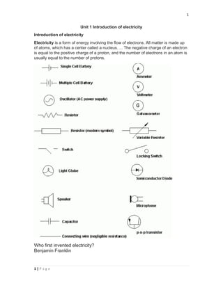
  • 1. 1 1 | P a g e Unit 1 Introduction of electricity Introduction of electricity Electricity is a form of energy involving the flow of electrons. All matter is made up of atoms, which has a center called a nucleus. ... The negative charge of an electron is equal to the positive charge of a proton, and the number of electrons in an atom is usually equal to the number of protons. Who first invented electricity? Benjamin Franklin
  • 2. 2 2 | P a g e Building upon Franklin's work, many other scientists studied electricity and began to understand more about how it works. For example, in 1879, Thomas Edison invented the electric light bulb and our world has been brighter ever since How electricity was first discovered? Italian physicist Alessandro Volta discovered that particular chemical reactions could produce electricity, and in 1800 he constructed the voltaic pile (an early electric battery) that produced a steady electric current, and so he was the first person to create a steady flow of electrical charge Generation of electricity  Heat (thermal) energy generated from: fossil fuels; coal. petroleum. natural gas. solar thermal energy. geothermal energy. nuclear energy.  Potential energy from falling water in a hydroelectric facility.  Wind energy.  Solar electric from solar (photovoltaic) cells.  Chemical energy from: fuel cells. batteries. Types of current There are two types of electric current: direct current (DC) and alternating current (AC). The electrons in direct current flow in one direction. The current produced by a battery is direct current. The electrons in alternating current flow in one direction, then in the opposite direction—over and over again. Scope of electricity  For household electric power supply system. eg: TV, Fan Lights etc.  For industrial power supply system.  Street light provide.  Operating different kinds of machine and equipment. Unit 2 Fundamentals of electric circuits What is voltage? Voltage is what makes electric charges move. It is the 'push' that causes charges to move in a wire or other electrical conductor. ... Voltage is also called, in certain circumstances, electromotive force (EMF). Voltage is an electrical potential difference, the difference in electric potential between two places. It can be expressed in terms of SI base units (m, kg, s, and A) as V= Potential Energy/ Charge = J/C = kg.m2 /A.s3 It can also be expressed as amperes times ohms (current times resistance, Ohm's law), watts per ampere (power per unit current, definition of electric power), or joules per coulomb (energy per unit charge), which is also equivalent to electronvolts per elementary charge: V=A. Ω = W/A=J/C= eV/e
  • 3. 3 3 | P a g e What is Current? Current is a flow of electrical charge carriers, usually electrons or electron-deficient atoms. ... Physicists consider current to flow from relatively positive points to relatively negative points; this is called conventional current or Franklin current. Electrons, the most common charge carriers, are negatively charged What is resistance? The electrical resistance of an object is a measure of its opposition to the flow of electric current. The inverse quantity is electrical conductance, and is the ease with which an electric current passes. Electrical resistance shares some conceptual parallels with the notion of mechanical friction. The SI unit of electrical resistance is the ohm (Ω), while electrical conductance is measured in siemens(S). Ohm's law defines the relationship between thevoltage, current, and resistance in an electric circuit: i = v/r. The current is directly proportional to the voltage and inversely proportional to theresistance The resistance (R) of an object is defined as the ratio of voltage across it (V) to current through it (I), while the conductance (G) is the inverse: R=V/I and G=I/V=1/R Types of Electrical Conductors  Hard Drawn Copper Conductor. ...  Cadmium Copper Conductor. ...  Steel-Cored Copper Conductor (SCC) ...  Copper Welded Conductor. ...  Hard-Drawn Aluminium Conductor or All-Aluminum Conductor. ...  Aluminium Conductor Steel Reinforced. ...  Smooth Body ACSR Conductor. ...  Expanded ACSR Conductor. What Are Two Types of Electrical Circuits?  Series Circuit. A series circuit has only one path for electricity to flow from one point to another. ...  Parallel Circuit. A parallel circuit has multiple paths for electricity to flow from one point to another. ...
  • 4. 4 4 | P a g e Measurement of current, voltage, resistance and power Ampere meter An ammeter (from Ampere Meter) is a measuring instrument used to measure the current in a circuit. Electric currents are measured in amperes (A), hence the name Ampere meter. The majority of ammeters are either connected in series with the circuit carrying the current to be measured (for small fractional amperes), or have their shunt resistors connected similarly in series. In either case, the current passes through the meter or (mostly) through its shunt Volt meter A voltmeter is an instrument used for measuring electrical potential difference between two points in an electric circuit. Analog voltmeters move a pointer across a scale in proportion to the voltage of the circuit; digital voltmeters give a numerical display of voltage by use of an analog to digital converter. Ohmmeter An ohmmeter is an electrical instrument that measures electrical resistance, the opposition to an electric current. Micro-ohmmeters (microhmmeter or microohmmeter) make low resistance measurements. Megohmmeters (also a trademarked device Megger) measure large values of resistance. Power Meters/ Watt meter/Energy meter. A power meter is an electric meter that measures the amount of electrical energy consumed by residences, businesses or electrically powered devices. These meters continuously measure the instantaneous voltage and current to give a reading of energy used.
  • 5. 5 5 | P a g e Unit 3 Electrical Energy Transformation An energy transformation is the change of energy from one form to another. Energy transformationsoccur everywhere every second of the day. There are many different forms of energy such as electrical, thermal, nuclear, mechanical, electromagnetic, sound, and chemical.
  • 6. 6 6 | P a g e Transformer, its function and application: A transformer is a static electrical device that transfers electrical energy between two or more circuits. A varying current in one coil of the transformer produces a varying magnetic flux, which, in turn, induces a varying electromotive force across a second coil wound around the same core. Electrical energy can be transferred between the two coils, without a metallic connection between the two circuits. Transformers are used for increasing or decreasing the alternating voltages in electric power applications, and for coupling the stages of signal processing circuits. Transformer is used to increase or decrease the voltage in electrical line. It can increase or decrease the value of capacitor, an inductor or resistance in an AC circuit. It can thus act as an impedance transferring device. Isolator, its function and application: An isolator is a mechanical switching device that, in the open position, allows for isolation of the input and output of a device. An isolator is a device used for isolating a circuit or equipment from a source of power. In electrical engineering, a disconnector, disconnect switch or isolator switch is used to ensure that an electrical circuit is completely de-energized for service or maintenance. Disconnectors can be operated either manually or automatically. It is electronic devise made by using MOSFET (The Metal-Oxide-Semiconductor Field-Effect Transistor is a type of field-effect transistor, most commonly fabricated by the controlled oxidation of silicon. It has an insulated gate, whose voltage determines the conductivity of the device.) or BJT (A bipolar junction transistor (bipolar transistor or BJT) is a type of transistor that uses both electron and hole charge carriers. In contrast, unipolar transistors). Miniature Circuit Breaker It is on load Device, operated automatically and acts as switch. A miniature circuit breaker (MCB) automatically switches off electrical circuit during an abnormal condition of the network means in overload condition as well as faulty condition. Nowadays we use an MCB in low voltage electrical network instead of a fuse. Handling an MCB is electrically safer than a fuse. Figure 1 Ideal transformer and induction law
  • 7. 7 7 | P a g e Electric poles, its function and application Utility poles are commonly used to carry two types of electric power lines: distribution lines (or "feeders") and subtransmission lines. Subtransmission lines carry higher voltage power from regional substations to local substations. The distance between two OHE (Over Head Equipment) Poles is usually 50 meters. It should not exceed 54 meters. The wire is at about 5.50m from the rail level. Utility poles are commonly used to carry two types of electric power lines:[2] distribution lines (or "feeders") and subtransmission lines. Distribution lines carry power from local substations to customers. They generally carry voltages from 4.6 to 33 kilovolts (kV) for distances up to 30 miles, Electrical safety tips:  Never put fingers or other objects in an outlet.  Keep metal objects out of toasters.  Never use anything with a cord or plug around water.  Never pull a plug out by its cord.  Stay away from substations and power lines.  Don't climb on power poles.  Never fly kites near power lines.  Don't touch someone who's been electrocuted! ...  Know your Electrical Code. ...  Always use GFCIs (ground-fault circuit interrupter) in damp or wet work areas. ...  Inspect & maintain your electrical tools. ...  Follow proper lockout/tagout procedures. ...  Wear the right safety gear. ...  Choose the right ladder. ...  Avoid power lines. Unit 4 Measuring Instruments and Protecting Devices Foot and meter/scale (Linear measuring instruments) A tape measure or measuring tape is a flexible ruler and used to measure distance. It consists of a ribbon of cloth, plastic, fiber glass, or metal strip with linear-measurement markings. It is a common measuring too. It is use to measure linear length in different unit such as meter and feet. Inch is small unit of feet similarly millimeter is small unit of meter.
  • 8. 8 8 | P a g e Vernier caliper/caliper A vernier scale is a visual aid to take an accurate measurement reading between two graduation markings on a linear scale by using mechanical interpolation; thereby increasing resolution and reducing measurement uncertainty by using Vernier acuity to reduce human estimation error. Purpose: Measuring more precisely than could be done unaided when reading a uniformly divided straight or circular measurement scale Standard wire gauge British Standard Wire Gauge is a set of wire sizes given by BS 3737:1964 (now withdrawn), and is generally abbreviated to SWG. It is also known as: Imperial Wire Gauge or British Standard Gauge. Use of SWG sizes has fallen greatly in popularity, but is still used as a measure of thickness in guitar strings and some electrical wire. Cross sectional area in square millimeters is now the more usual size measurement for wires used in electrical installation cables. The current British Standard for metallic materials such as wire and sheet is BS 6722:1986, which is a solely metric standard. feeler gauge A feeler gauge is a tool used to measure gap widths. Feeler gauges are mostly used in engineering to measure the clearance between two parts.[1] They consist of a number of small lengths of steel of different thicknesses with measurements marked on each piece. They are flexible enough that, even if they are all on the same hinge, several can be stacked together to gauge intermediate values What is the measuring range for radius gauge? A radius gauge, also known as a fillet gauge, is a tool used to measure the radiusof an object. Radius gauges require a bright light behind the object to bemeasured. The gauge is placed against the edge to be checked and any light leakage between the blade and edge indicates a mismatch that requires correction. Micrometer
  • 9. 9 9 | P a g e A gauge that measures small distances or thicknesses between its two faces, one of which can be moved away from or towards the other by turning a screw with a fine thread. Miniature Circuit breaker (MCB) A circuit breaker is an automatically operated electrical switch designed to protect an electrical circuit from damage caused by excess current from an overload or short circuit. Its basic function is to interrupt current flow after a fault is detected. Unlike a fuse, which operates once and then must be replaced, a circuit breaker can be reset (either manually or automatically) to resume normal operation. What are the different sources of electric power? The three major categories of energy for electricity generation are fossil fuels (coal,natural gas, and petroleum), nuclear energy, and renewable energy sources. Most electricity is generated with steam turbines using fossil fuels, nuclear, biomass, geothermal, and solar thermal energy. Direct current (DC) is the unidirectional flow of an electric charge. A battery is a prime example.... electricity and water as byproducts) also produce only DC. Light aircraft electrical systems are typically 12 V or 24 V DC similar to automobiles. Alternating current (AC) is an electric current which periodically reverses direction, in contrast to ... High-voltage direct-current (HVDC) electric power transmission systems have become more viable as technology has provided efficient means ... The single-phase power supply has one distinct wave cycle whereas; three phase has three distinct wave cycles. Single phase requires the single wire to connect the circuit whereas; 3-phase needs 3-wires. The voltage of the single phase is 230V, whereas three phase voltage is 415V. single-phase power three phase power 1. Mostly use in Domestic Propose. 1. Mostly use in Industries, factory
  • 10. 10 10 | P a g e What is a power inverter? An inverter is a critical piece of equipment in any PV system. The inverter takes DC power, either from your solar panels or batteries, and turns it into AC power, ready and usable for your household appliances. Grid-tie and off-grid solar systems use different types of inverters. The Solar Inverter is an essential device in any solar power system. Its basic function of the inverter is to change the variable Direct Current output of the solar panels into Alternating Current. ... The primary function of an inverter is to convert Direct Current (DC) power into standard, Alternating Current (AC). Solar power is the conversion of energy from sunlight into electricity, either directly using photovoltaics (PV), indirectly using concentrated solar power, or a combination. Concentrated solar power systems use lenses or mirrors and tracking systems to focus a large area of sunlight into a small beam. Photovoltaic cells convert light into an electric current using the photovoltaic effect. A solar cell, or photovoltaic cell (PV), is a device that converts light into electric current using the photovoltaic effect. Earthing System Introduction of earthing In an electrical installation, an earthling system or grounding system connects specific parts of that installation with the Earth's conductive surface for safety and functional purposes. The point of reference is the Earth's conductive surface. The choice of earthing system can affect the safety and electromagnetic compatibility of the installation. Regulations for earthing systems vary considerably
  • 11. 11 11 | P a g e What is the function of earthing? In an electrical installation, an earthing system or grounding system connects specific parts of that installation with the Earth's conductive surface for safety and functional purposes. The point of reference is the Earth's conductive surface. Earthing is used to protect you from an electric shock. It does this by providing a path (a protective conductor) for a fault current to flow to earth. It also causes the protective device (either a circuit-breaker or fuse) to switch off the electric current to the circuit that has the fault. Objectives of electrical earthing Protective earthing An earth ground connection of the exposed conductive parts of electrical equipment helps protect from electric shock by keeping the exposed conductive surface of connected devices close to earth potential, when a failure of electrical insulation occurs. When a fault occurs, current flows from the power system to earth. Functional earthing A functional earth connection serves a purpose other than electrical safety, and may carry current as part of normal operation.[1] For example, in a single-wire earth return power distribution system, the earth forms one conductor of the circuit and carries all the load current. Other examples of devices that use functional earth connections include surge An electric shock is a dangerous and painful physiological effect caused by the passing of an electric current through the body of a human or animal. ... An electric shock is a dangerous and painful physiological effect caused by the passing of an electric current through the body of a human or animal. Effects of electric shock on human body Nerves are tissue that offers very little resistance to the passage of an electric current. When nerves are affected by an electric shock, the consequences include pain, tingling, numbness, weakness or difficulty moving a limb. These effects may clear up with time or be permanent.
  • 12. 12 12 | P a g e In this article we will go to give you a brief overview of different types of grounding systems and Methods of Earthing. 1. TT Earthing system:- This system normally used for consumer power supply. No earthing system provided by power distributor. The owner must install the earthing protection by their own connection to the earth. They must installing a suitable electrode and safe arrangement for which they are responsibility to their installation. The neutral and earthing conductor must be separately through the installation because power distributor only provide the supply neutral or protective conductor for the connection to consumer. 2. IT Earthing system:- This system is similar with TT system but totally different in earthing supply. The distributor system not have any connections to earth or it have only a high impedance connection. It mean the usual protection is not effective for this system. This type is not for consumer power supply. It special for power distributor such as substation or generator area. 3. TN-S Earthing system:- This system has the neutral of power supply with connection of earth only at one point to the source. the consumer’s earthing terminal is usually connected to the metallic Armour of the distributor’s cable into the High voltage and low Voltage transformer.
  • 13. 13 13 | P a g e 4. TN-C-S Earthing system:- This system has the supply neutral conductor of a distribution main connected with earth at source as protective multiple earthing. The supply distributor neutral conductor is also used to return earth fault currents from the consumer installation back to the source with a safely manner. The power supply distributor will provide a consumer’s earthing terminal which is linked to the incoming neutral conductor. This combined earth and neutral system called the protective and neutral conductor or the combined neutral and earth conductor. 5. TN-C Earthing system:- This system is not familiar or unusual for earthing system. It a combined neutral conductor fulfills the functions of both a PE and an N conductor. The neutral conductor is the sheath of a cable and therefore is concentric with (totally surrounds) the phase conductor. Earthing can be done in many ways. The various methods employed in earthing, (in house wiring or factory and other connected electrical equipment and machines) are discussed as follows.
  • 14. 14 14 | P a g e Now we will brief Methods of Earthing 1. Plate Earthing:- In plate earthing system, a plate made up of either copper with dimensions 60cm * 60cm * 3.18mm or galvanized iron of dimensions 60cm * 60cm * 6.35 mm is buried vertical in the earth pit, which should not be less than 3meter from the ground level. 2. Pipe Earthing:- A galvanized steel and a perforated pipe of approved length and diameter is placed vertically in a wet soil in this kind of system of earthing. It is the most common system of earthing. 3. Earthing through the Water man:- In this method of earthing, the waterman (Galvanized GI) pipes are used for earthing purpose. Make sure to check the resistance of GI pipes and use earthing clamps to minimize the resistance for proper earthing connection.
  • 15. 15 15 | P a g e 5. Strip or Wire Earthing:- In this method of earthing, strip electrodes of cross- section not less than 25mm * 1.6mm is buried in a horizontal trenches of a minimum depth of 0.5meter. If copper with a cross-section of 25mm * 4mm is used and a dimension of 3.0mm. if it’s a galvanized iron or steel. Unit 8 Electric Wiring Procedure What is electrical layout plan? Electrical Plan. Electrical plan is “a preplan of electrical design on a paper before the physical installation of electrical appliances and machines in real time”. This electrical plan consists of several standard symbols of electrical appliances and machines and their interconnection.
  • 16. 16 16 | P a g e Types of Electrical Wiring Systems The state electricity board provides the electric supply up to the outside the consumer’s premises. The consumer has to take the connection from that point to the main switchboard at home. From the main switchboard, various types of electrical loads such as fans, lights, room coolers, and refrigerators are connected through the wires.There are different types of wirings used for connecting the loads to the mains which can be used for house electrical wiring as well as industrial electrical wiring. Some of these are discussed below. Cleat Wiring In this, porcelain, wood or plastic cleats are fixed to walls or ceilings at regular intervals, i.e., 0.6 m between each cleat. PVC insulated cables are taken through the holes of each cleat and hence cleat support and holds wire.This is an inexpensive method of wiring and is used for temporary installations. Therefore, it is not suitable for home electrical wiring and also it is an outdated method. Casing and Capping Wiring In this cable is run through a wood casing having grooves. The wood casing is prepared in such a way that it is of a required fixed length with parallel grooves that accommodates the cables. The wooden casing is fixed to the walls or ceiling with screws. After placing the cables inside the grooves of casing, a wooden cap with grooves is placed on it to cover the cables. This is also a cheap wiring system, but there is a high risk of fire in case of short circuits.
  • 17. 17 17 | P a g e Batten Wiring In this, insulated wires are run through the straight teak wooden battens. The wooden battens are fixed on the ceilings or walls by plugs and screws. The cables are fitted onto the battens by using tinned brass link clips. These clips are fixed to the battens with rust-resistant nails. This wiring installation is simple and cheap as compared to other electrical wiring systems also takes less time to install. These are mainly used for indoor installations. Conduit Wiring In this wiring, PVC cables are taken through either PVC conduit pipes or through steel conduit pipes. This conduit wiring can be either surface conduit wiring or concealed conduit wiring. If the conduit pipes are run on surface of the walls and ceilings, it is called a surface conduit wiring. If the conduits are run inside the surface of the walls and ceilings and are covered with plastering, it is called as concealed conduit wiring. Surface conduit wiring is used in industries to connect the heavy motors. On the other hand, concealed wiring is the most popular and common method of wiring the residential buildings. The conduit wiring is the safest method of wiring and also looks beautiful (concealed conduit wiring). Types of Drawings Electrical drawings plays an important role in electrical installation works that they convey information about connection of various devices and equipments with mains. The information on drawings provides the complete design or plan of electrical installation and also helps to assemble the various equipments. Some of the electrical wiring diagrams are discussed below. Before knowing about these diagrams, first one must aware and have idea about various symbols used while preparing drawing and also for understanding the wiring connections. Check out various electrical wiring symbols .
  • 18. 18 18 | P a g e Block Diagram It is a functional drawing which shows and describes the main operating principles of the equipment or devices. It consists of principle functions or parts represented by blocks and are connected through lines that show the relationship between the blocks.This diagram is usually drawn before implementing a circuit diagram. It will not give any detailed information about the system and also leaves the information about smaller components. And hence, most technicians have limited interest about this diagram. Circuit Drawing (Diagram) In this, electrical circuit is graphically represented in a simplified manner. It includes the position information (in cm or m or mm) of various elements like light fixtures, receptacle boxes, junction boxes, ceiling fans, etc. Line Diagram It is a simplified notation of an electrical system, also called as one-line diagram or single line diagram. It is similar to the block diagram except that various electrical elements such as transformers, switches, lights, fans, circuit breakers, and motors are represented by standard schematic symbols.
  • 19. 19 19 | P a g e It consists of symbols to represent the components and lines to represent the wires or conductors which connects the components together. The line diagram is actually derived from the block diagram. It doesn’t give any layout of the parts and their detail wiring information of the components. However, one can do wiring by following the information given in this diagram. These diagrams are usually intended to illustrate the working of an electric circuit. Wiring Diagram The electrical wiring diagram is a pictorial representation of the circuit which shows the wiring between the parts or elements or equipments. It gives detailed information about wiring such that one can get an idea of making connection between the devices. It includes relative position, arrangement of the devices and also terminals on the devices. It shows power supplies and earth connections, control and signal functions (with simplified shapes), termination of unused contacts and leads, interconnection via plugs, blocks, sockets, terminal posts, lead-through, etc.
  • 20. 20 20 | P a g e Wiring Schedule It is a list of cables or wires used in the installation with its reference number, length, type and the amount of insulation stripping required for soldering the cable. It gives the raceways of the wire and also starting and termination points. In some complex equipment, wiring table gives the interconnection of the equipments (such as motors and heaters) with starting and finishing reference points. It also includes the wire identification markings, wire colors, size and so on. Parts List Although it is not a drawing, parts list is an integral part of drawing which defines the various symbols and parts used in other drawings such as wiring diagram, line diagram, and block diagram. It gives the information of circuit component types with related to their reference numbers. This list is useful for identifying, locate and cross refer the actual component labeled or given in other electrical drawings in order to ensure the choice of appropriate parts before doing the electrical wiring. Wiring Preparation As we are discussing the sequence of steps in wiring like understanding the safety, knowing types of wiring systems, understanding the difference among various electrical drawings and symbols, the next step of electrical wiring process is the preparation of wires or cables and electrical tools. Types of Electrical Wiring We know that electrical circuit is a closed path through which electricity flows from phase or hot wire to the device or apparatus and then back the source though neutral wire. Along the way, the electricity path may consist of fixtures, switches, receptacles, junction boxes, etc. So the wiring may be routed through these elements before actually making connections with apparatus or device. Majorly, the wiring is divided into two types, namely parallel wiring and series wiring depending on the way the devices are powered or connected to the supply.
  • 21. 21 21 | P a g e In parallel wiring, several devices on the installation are powered on a single circuit. It is the most accepted wiring in homes and industries, in which devices are connected in parallel with the supply source as shown in figure. In this, both phase (or hot) and neutral cables are routed through the electrical boxes (junction boxes) from which individual receptacles, fixtures, and devices are branched. The series wiring is the rarely used wiring in which hot wire is routed through the several devices and then last device terminal is connected to the neutral wire. It is like an old Christmas lights or serial lights wiring in which one light burnout leads to the shutdown of the entire network.
  • 22. 22 22 | P a g e Examples of Electrical Wiring For a better understanding of the wiring concept, here we are giving some examples of the wiring circuits which we are dealing daily in our homes. Single bulb controlled by a one way switch In this, hot wire is connected to the one terminal of the switch and other terminal of the switch is connected to the bulb positive terminal, then bulb negative terminal is connected to the neutral wire as shown in figure.
  • 23. 23 23 | P a g e Two blubs are controlled by a one way switch In this, two bulbs are connected in parallel with the supply wires (phase and neutrals) which are routed by single one-way switch as shown in figure. Single blub (or any other load) controlled by two way switches This wiring is also called as staircase wiring in which a light lamp is controlled from two sources by using two two-way switches. This type of wiring is used in bed rooms to switch ON/OFF the lamp from two sources (at the bed side and at switchboard). The connection of switches with the lamp is shown below.
  • 24. 24 24 | P a g e Godown Wiring This type wiring is used in big godowns, long passages, warehouses and tunnel like structures having many rooms or portions. It follows the linear sequence for switching the lights from one end to the other. When a person leaves from one room and enters next, by turning the light switch makes earlier lamp switched OFF while present room is switched ON. It turns OFF the lamp while switching another. The schematic wiring diagram for godown wiring is shown in below.
  • 25. 25 25 | P a g e Fluorescent lamp controlled by a one-way switch The switching of fluorescent lamp with single one-way switch through ballast and capacitor is shown in below figure. In this, phase wire is connected to the one end of the switch and another end of the switch is connected to the choke (or ballast). One electrode of the lamp is connected to the choke and other to neutral terminal as shown in figure. Socket outlet wiring The outlet holds a plug and passes the current through it when the power is routed to the socket through a switch. The single socket connection and radial socket connection are shown in below figure.
  • 26. 26 26 | P a g e Control switch board wiring The schematic diagram for a control switch board is shown in below figure in which ceiling fan, fluorescent lamp and light bulb are controlled by appropriate switches.
  • 27. GROUND FLOOR PLAN FIRST FLOOR PLAN SECOND FLOOR PLAN TYPICAL LAYOUT OF SDB (NOT TO SCALE) S P M C B D P M C C B LEGEND FIXING POSITIONSYMBOL Single pole switch Sub distribution board DESCRIPTION Tube light Telephone outlet 5 -15 APower socket Television outlet Bell Wall Light Main distribution bar 1800 mm Above FFL 1300 mm Above FFL 250 mm Above FFL Mirror light (wall) power circuit line light circuit line n no.s of 3/18 cu wire 2 x 3/18 + 1 x 3/22 cu wire LED panel light(9 w) foot light compact flurescent lamp( 2 x 20 w) 32 A TPN KWH METER (SUPPLIED BY NEA) 40 A TPN MCCB 4X16+ 1X6 -E SP&N 32A E MAIN CONTROL PANEL 1X10sq.mmCUCABLE sq. mm CU CABLE CHANGEOVER 4X16 + 1X6 -E sq. mm CU CABLE FOR DG/NORMAL SP&N 20A FUTURE SECOND SP&N 32A SP&N 32A THIRD E 4X16+ 1X6 -E sq. mm CU CABLE SP&N 32A E SPARE SP&N 32A FIRSTGROUND 12345 KWH 20-40 kWH 12345 KWH 20-40 kWH BACKUP DIESEL GENRATOR (20 kVA, 400 V, 50 Hz, 0.8 pf) 6A 16A 16A PC2 (2x6+1x2.5) sq. mm; Copper single core PVC cable drawn inside 25 mm ∅ conduit PC1 from Main Control Panel 6A LC4 6A LC3 16A PC3 SPR 16A PC9 (2x6+1x2.5) sq. mm; Copper single core PVC cable drawn inside 25 mm ∅ conduit from Main Control Panel SPR 6A LC12 6A LC10 16A PC10 6A LC13 PC11 TOEQUIPMENT 150 600 900 SURROUNDED BY SALT 150 150 SALT SALT 600 X 600 X 3.14 MM CHARCOAL 600150 900 10 MM SQ. COPPER CONDUCTOR IN GI PIPE 150 200 125 500 WIRE MESH 32 MM GI PIPE FOR WATERING FUNNEL C.I. COVER WITH FRAME 0.00 LEVEL P.C.C. COPPER PLATE AND CHARCOAL E.. GROUND STATION 6A LC5 16A 6A LC11 SPR 6A (2x6+1x2.5) sq. mm; Copper single core PVC cable drawn inside 25 mm ∅ conduit from Main Control Panel 6A LC17 6A LC15 6A LC18 6A LC16 16A PC17SPR SPR 6A (2x6+1x2.5) sq. mm; Copper single core PVC cable drawn inside 25 mm ∅ conduit from Main Control Panel 6A LC19 SPR 16A PC4 6A LC9 16A PC8 16A PC7 16A 16A 16A 16A Dome Light, 1 X 15w CFL PC12 PC13 16A16A PC5 16A SPR 6A6A LC2 6A LC1 GROUND FLOOR PLAN FIRST FLOOR PLAN SECOND FLOOR PLAN TOP FLOOR PLAN Light Points Layout Light Points LayoutLight Points Layout Light Points Layout POWER CIRCUIT LAYOUT POWER CIRCUIT LAYOUT POWER CIRCUIT LAYOUT 6A LC6 6A SPR 6A LC8 Car Porch Toilet U P 2 3 41 B C 2 3 41 B C U P A A Bed Room Bed Room Bed Room Bed Room 2 3 41 B C 2 3 41 B C U P A A Bed Room Bed Room 6" 6" 8" 2 3 41 B C 2 3 41 B C A A 13'-3"13'-11" W1 W4 W1 W1 W2 W3 W4 W1 W1 W1 W3 W1 W1 W4 W1 W1 W2 W2 D1 D1 D1 D1 D1 D1 D1 D1 D2 D2 D2 D1 MD D1 28'-2" 12'-9" 12'-5" 11'-9" 38'-1" 12'-9" 12'-5" 11'-9" 40'-9" 13'-3"13'-11" 28'-2" 13'-3"13'-11" 28'-2" 12'-9" 12'-5" 11'-9" 40'-9" 12'-9" 12'-5" 11'-9" 41'-3" 13'-3"13'-11" 28'-2" 13'-3"13'-11" 28'-2" 37'-11" 12'-9" 12'-5" 11'-9" 3'-10" 41'-3" 12'-9" 12'-5" 11'-9" Bed Room 12'-0"X 12'-0" Bed Room 12''0"X 12'-0" Store Room 7'-8"X 3'-5" Kitchen 11'-0"X 7'-8" 8'-0"X 4'-10"' Living /Dinning Room 21'-6"X 15'-1" 12'-10"X 12'-8" 13'-6"X 12'-8" Family Room 13'-7"X 11'-5" Toilet 8'-0"X 5'-8"' 12'-10"X 12'-8"13'-11"X 12'-9" 13'-2"X 11'-5" 13'-6"X 12'-8" W1 13'-3"13'-11" 28'-10" DW1 A A A A A A Terrace W4 W4 DW2 9" Balcony DW2 VoidVoid 6'-1" 6'-5" Car Porch Toilet U P 2 3 41 B C 2 3 41 B C U P A A Bed Room Bed Room Bed Room Bed Room 2 3 41 B C 2 3 41 B C U P A A Bed Room Bed Room 6" 6" 8" 2 3 41 B C 2 3 41 B C A A X X 13'-3"13'-11" W1 W4 W1 W1 W2 W3 W1 W1 W1 W3 W1 W1 W4 W1 W1 W2 W2 D1 D1 D1 D1 D1 D1 D1 D1 D2 D2 D2 D1 MD D1 28'-2" 12'-9" 12'-5" 11'-9" 38'-1" 12'-9" 12'-5" 11'-9" 40'-9" 13'-3"13'-11" 28'-2" 13'-3"13'-11" 28'-2" 12'-9" 12'-5" 11'-9" 40'-9" 12'-9" 12'-5" 11'-9" 2'-7" 41'-3" 13'-3"13'-11" 28'-2" 13'-3"13'-11" 28'-2" 37'-11" 12'-9" 12'-5" 11'-9" 3'-10" 41'-3" 12'-9" 12'-5" 11'-9" Bed Room 12'-0"X 12'-0" Bed Room 12''0"X 12'-0" Store Room 7'-8"X 3'-5" Kitchen 11'-0"X 7'-8" 8'-0"X 4'-10"' Living /Dinning Room 21'-6"X 15'-1" 12'-10"X 12'-8" 13'-6"X 12'-8" Family Room 13'-7"X 11'-5" Toilet 8'-0"X 5'-8"' 12'-10"X 12'-8"13'-11"X 12'-9" 13'-2"X 11'-5" 13'-6"X 12'-8" W1 13'-3"13'-11" 28'-10" 38'-5" 28'-2" 26'-2" 3'-7" 16'-7" DW1 A A A A A A Terrace Terrace Below Terrace W4 W4 DW2 Balcony DW2 VoidVoid 6'-1" 6'-5" 3' LC # 1 LC # 3 LC # 6 LC # 4 LC # 2 LC # 5 LC # 8 LC # 9 LC # 7 LC # 10 LC # 13 LC # 15 LC # 16 LC # 14 LC # 17 LC # 18 LC # 11 6A LC7 6A LC14 6A LC6
  • 28. GROUND FLOOR PLAN Car Porch Toilet U P 2 3 41 B C 2 3 41 B C A A 13'-3"13'-11" W1 W4 W1 W1 W2 W3 W4 D1 D2 D2 MD D1 28'-2" 12'-9" 12'-5" 11'-9" 38'-1" 12'-9" 12'-5" 11'-9" 40'-9" 13'-3"13'-11" 28'-2" Bed Room 12'-0"X 12'-0" Bed Room 12''0"X 12'-0" Store Room 7'-8"X 3'-5" Kitchen 11'-0"X 7'-8" 8'-0"X 4'-10"' Living /Dinning Room 21'-6"X 15'-1" A A W4 Void
  • 29. TOEQUIPMENT 150 600 900 SURROUNDED BY SALT 150 150 SALT SALT 600 X 600 X 3.14 MM CHARCOAL 600150 900 10 MM SQ. COPPER CONDUCTOR IN GI PIPE 150 200 125 500 WIRE MESH 32 MM GI PIPE FOR WATERING FUNNEL C.I. COVER WITH FRAME 0.00 LEVEL P.C.C. COPPER PLATE AND CHARCOAL 32 A TPN KWH METER (SUPPLIED BY NEA) 40 A TPN MCCB 4X16+ 1X6 -E SP&N 32A E MAIN CONTROL PANEL 1X10sq.mmCUCABLE sq. mm CU CABLE CHANGEOVER 4X16 + 1X6 -E sq. mm CU CABLE FOR DG/NORMAL SP&N 20A FUTURE SECOND SP&N 32A SP&N 32A THIRD E 4X16+ 1X6 -E sq. mm CU CABLE SP&N 32AE SPARE SP&N 32A FIRSTGROUND 12345 KWH 20-40 kWH 12345 KWH 20-40 kWH BACKUP DIESEL GENRATOR (20 kVA, 400 V, 50 Hz, 0.8 pf) LEGEND FIXING POSITIONSYMBOL Single pole switch Sub distribution board DESCRIPTION Tube light Telephone outlet 5 -15 APower socket Television outlet Bell Wall Light Main distribution bar 1800 mm Above FFL 1300 mm Above FFL 250 mm Above FFL Mirror light (wall) power circuit line light circuit line n no.s of 3/18 cu wire 2 x 3/18 + 1 x 3/22 cu wire LED panel light(9 w) foot light compact flurescent lamp( 2 x 20 w) Dome Light, 1 X 15w CFL TYPICAL LAYOUT OF SDB (NOT TO SCALE) S P M C B D P M C C B 6A 16A 16A PC2 (2x6+1x2.5) sq. mm; Copper single core PVC cable drawn inside 25 mm ∅ conduit PC1 from Main Control Panel 6A LC4 6A LC3 16A PC3 SPR 16A PC9 (2x6+1x2.5) sq. mm; Copper single core PVC cable drawn inside 25 mm ∅ conduit from Main Control Panel SPR 6A LC12 6A LC10 16A PC10 6A LC13 PC11 6A LC5 16A 6A LC11 SPR 6A (2x6+1x2.5) sq. mm; Copper single core PVC cable drawn inside 25 mm ∅ conduit from Main Control Panel 6A LC17 6A LC15 6A LC18 6A LC16 16A PC17SPR SPR 6A (2x6+1x2.5) sq. mm; Copper single core PVC cable drawn inside 25 mm ∅ conduit from Main Control Panel 6A LC19 SPR 16A PC4 6A LC9 16A PC8 16A PC7 16A 16A 16A 16A PC12 PC13 16A16A PC5 16A SPR 6A6A LC2 6A LC1 6A LC6 6A SPR 6A LC8 6A LC7 6A LC14 6A LC6