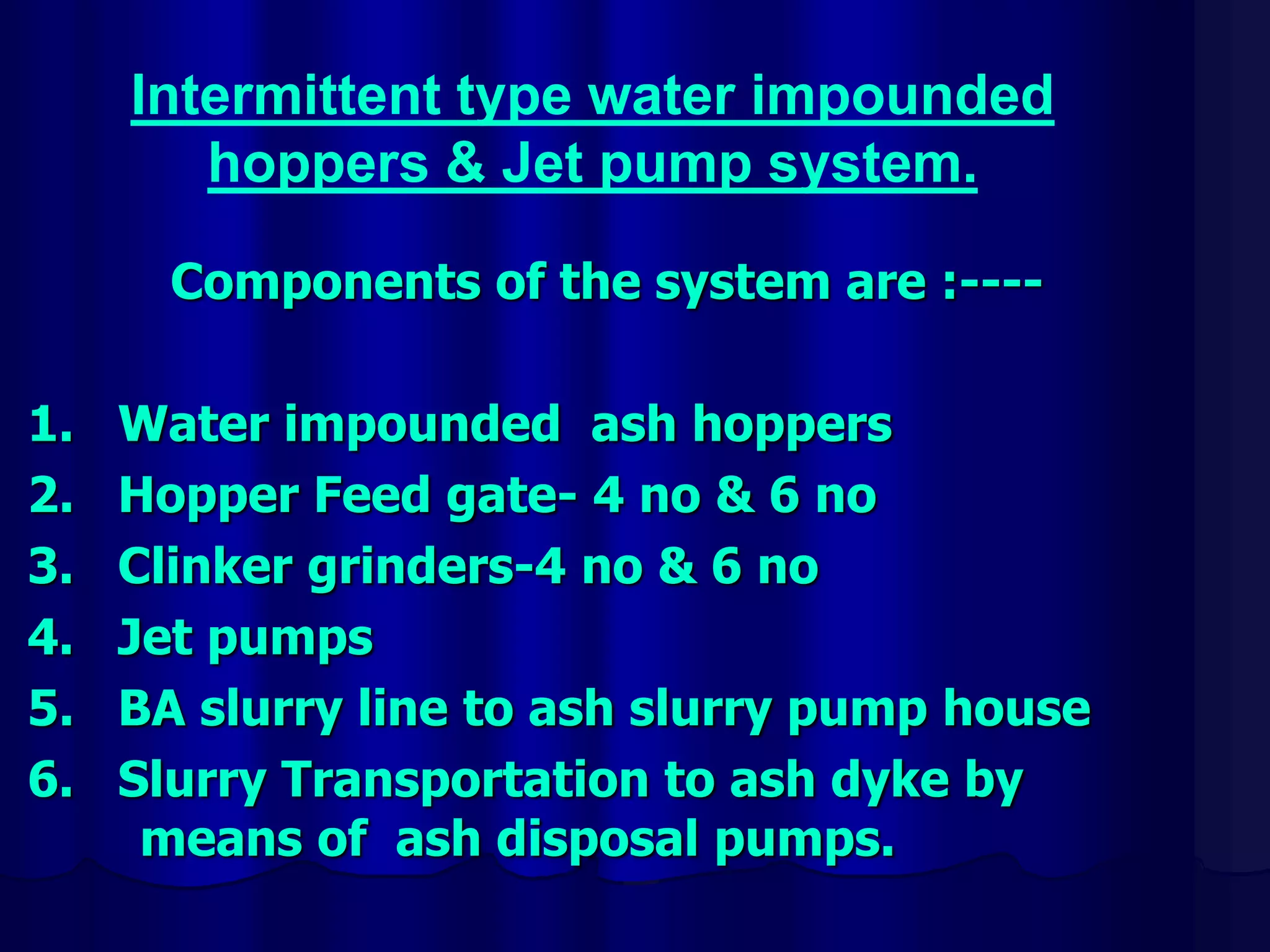
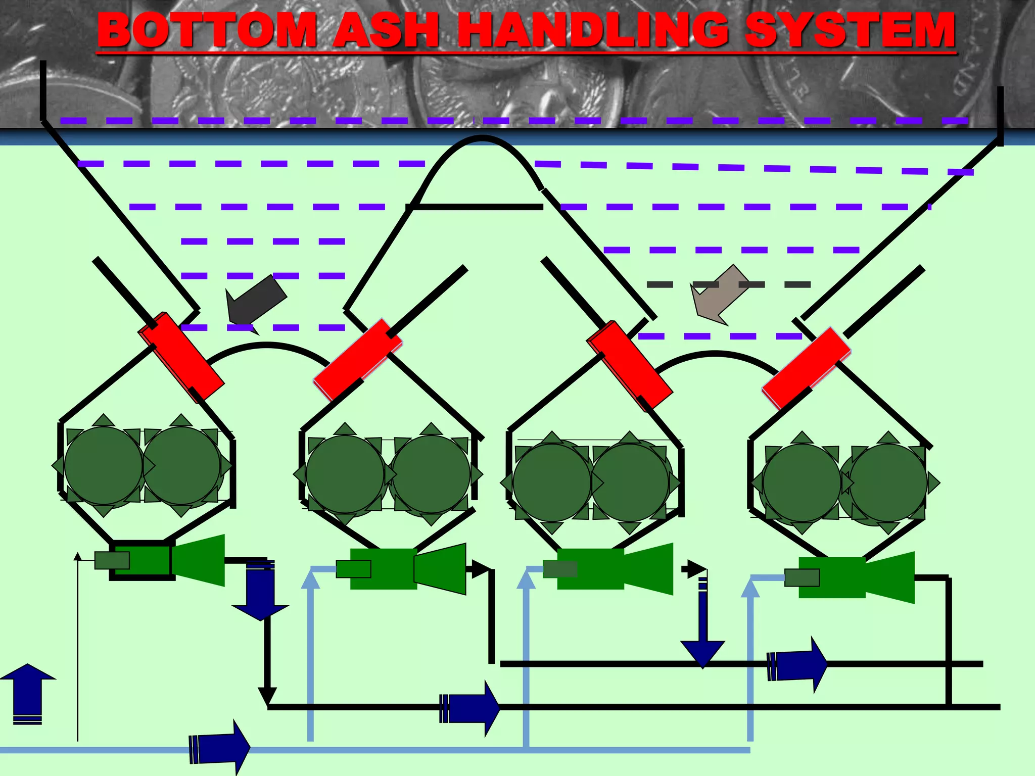
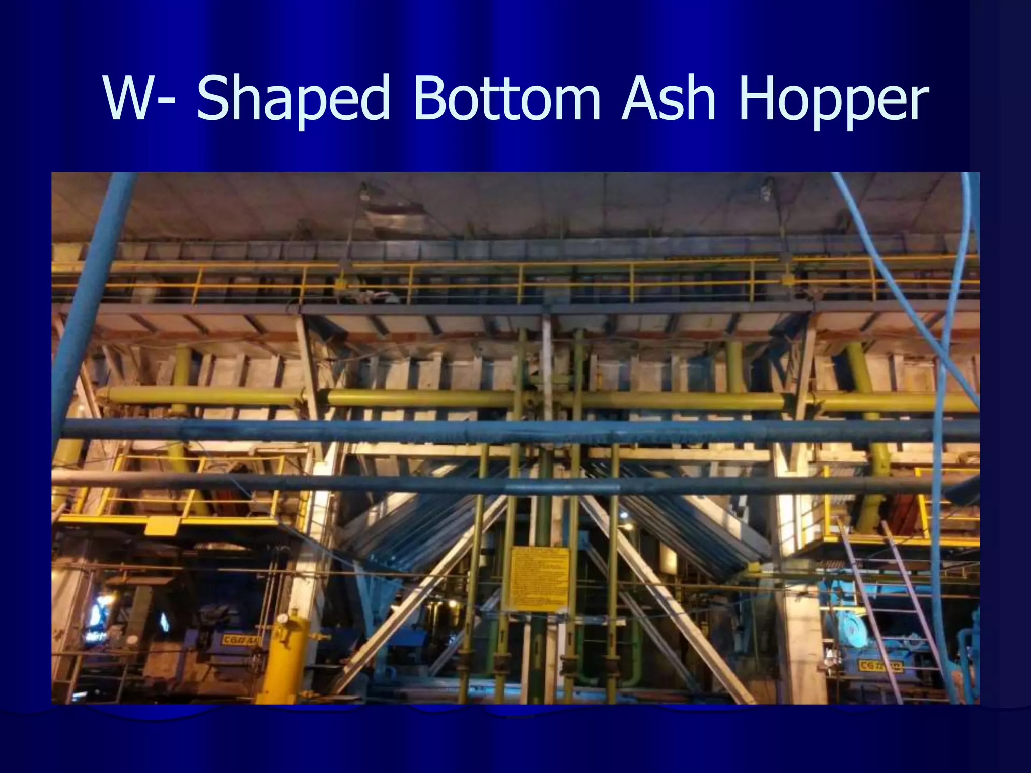
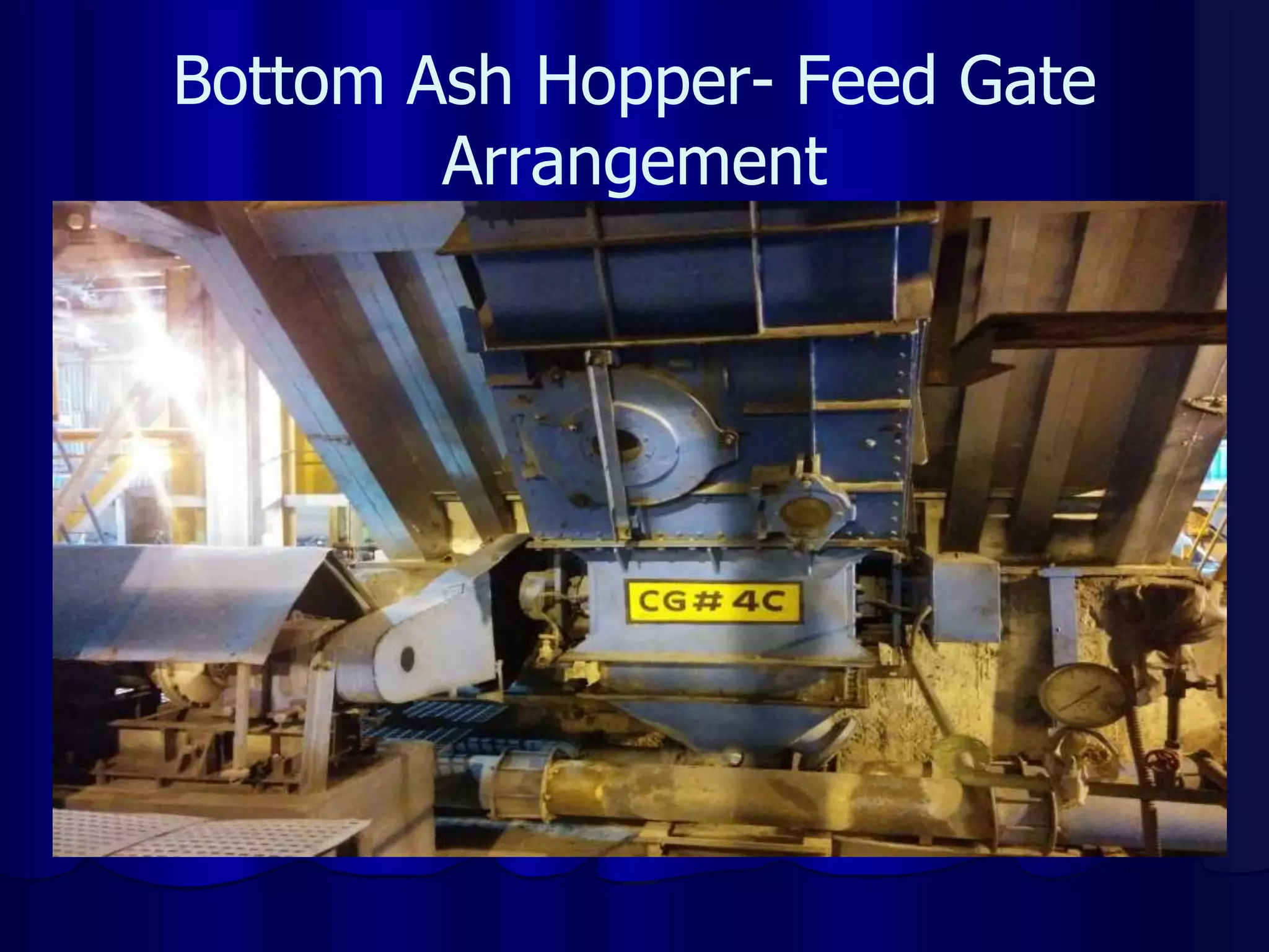
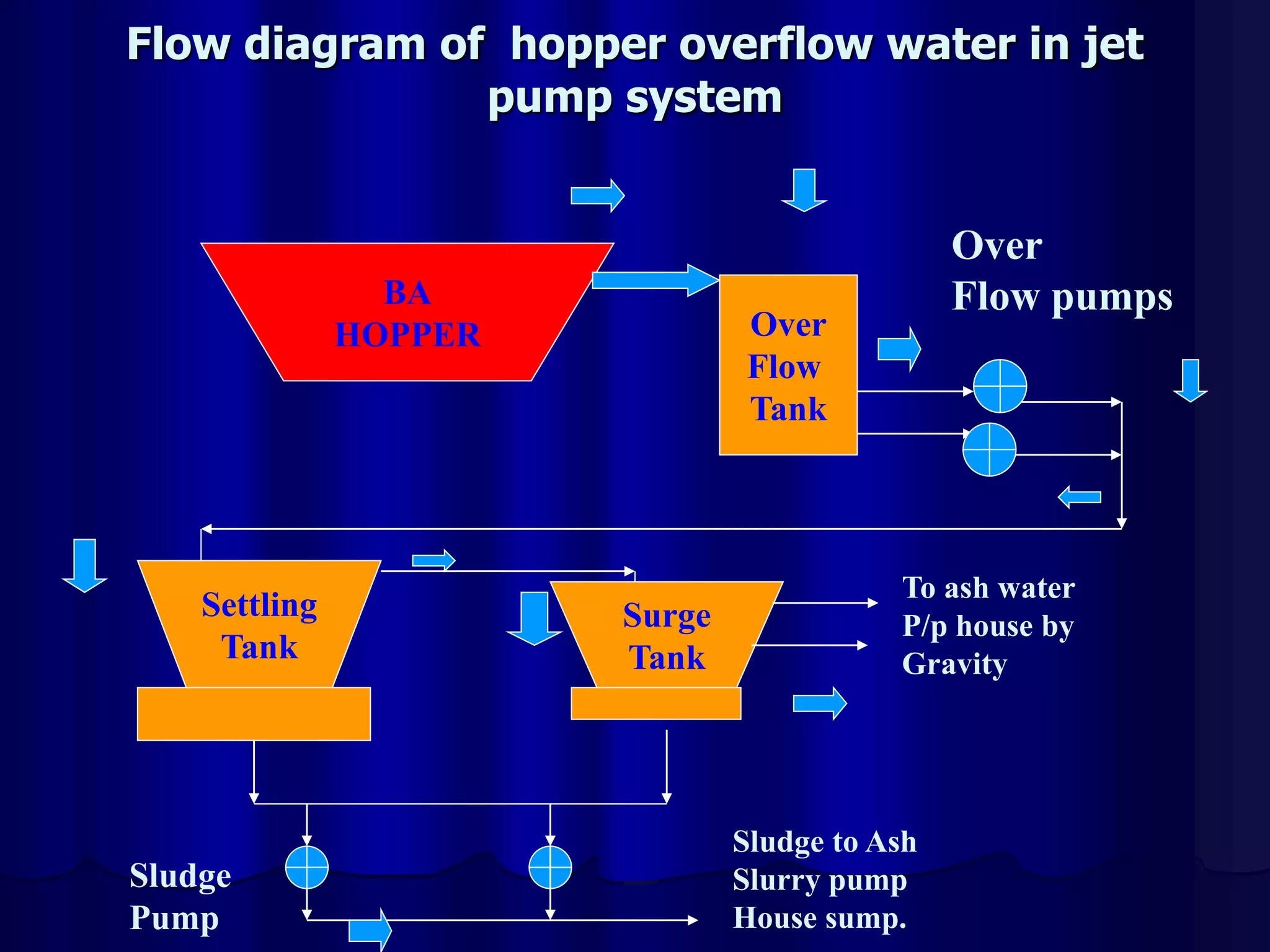
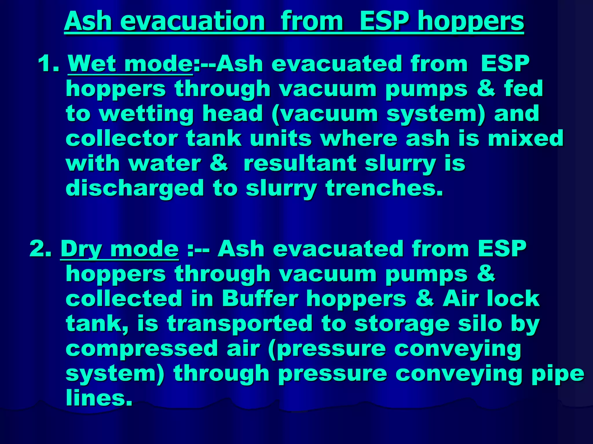
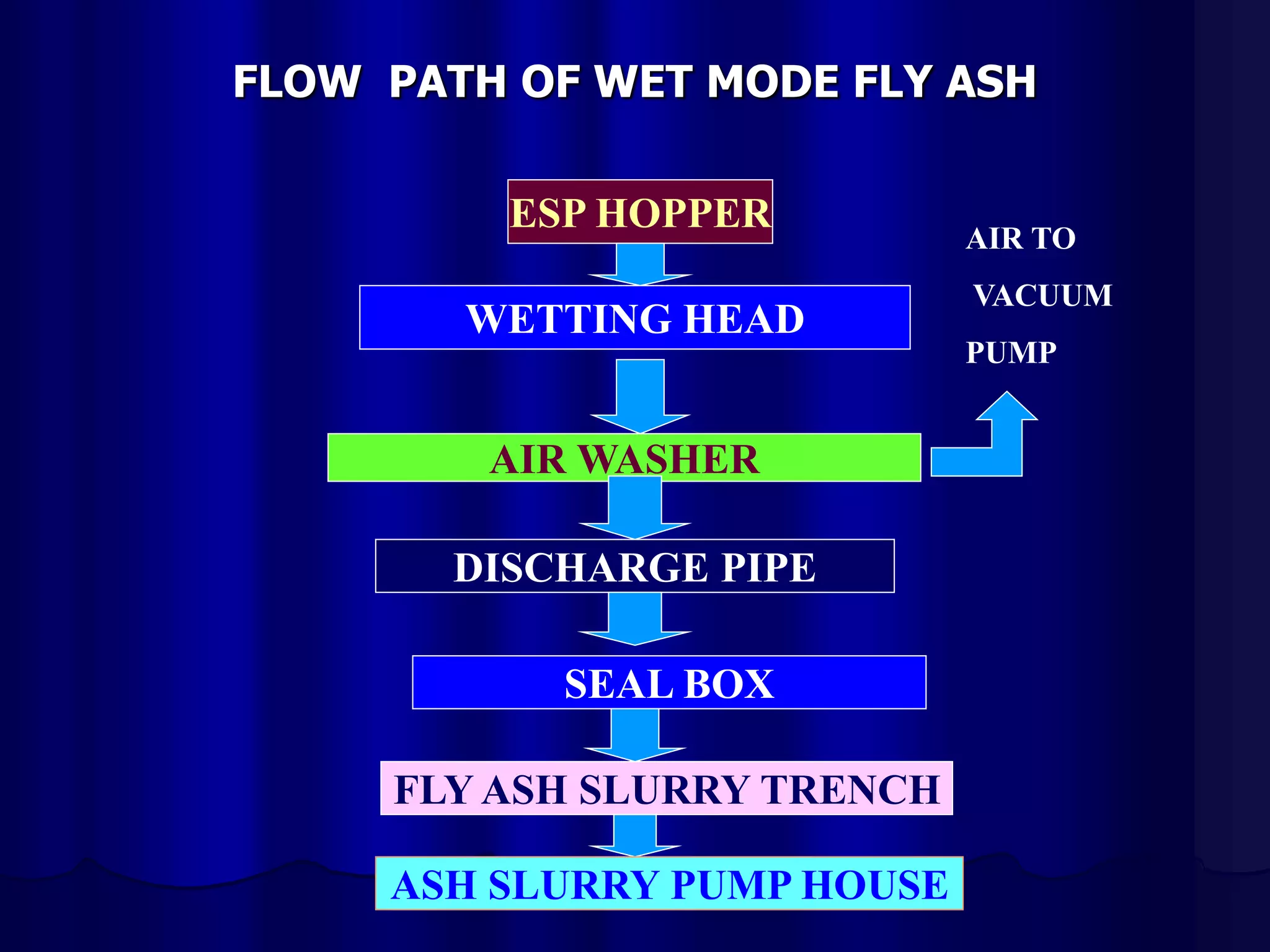
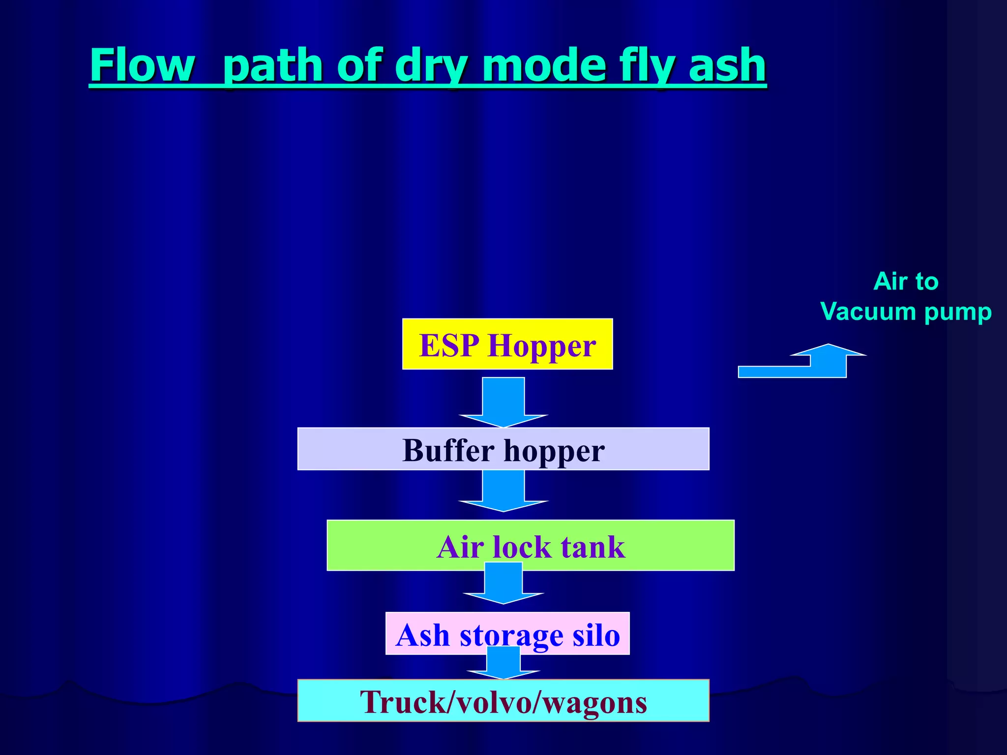
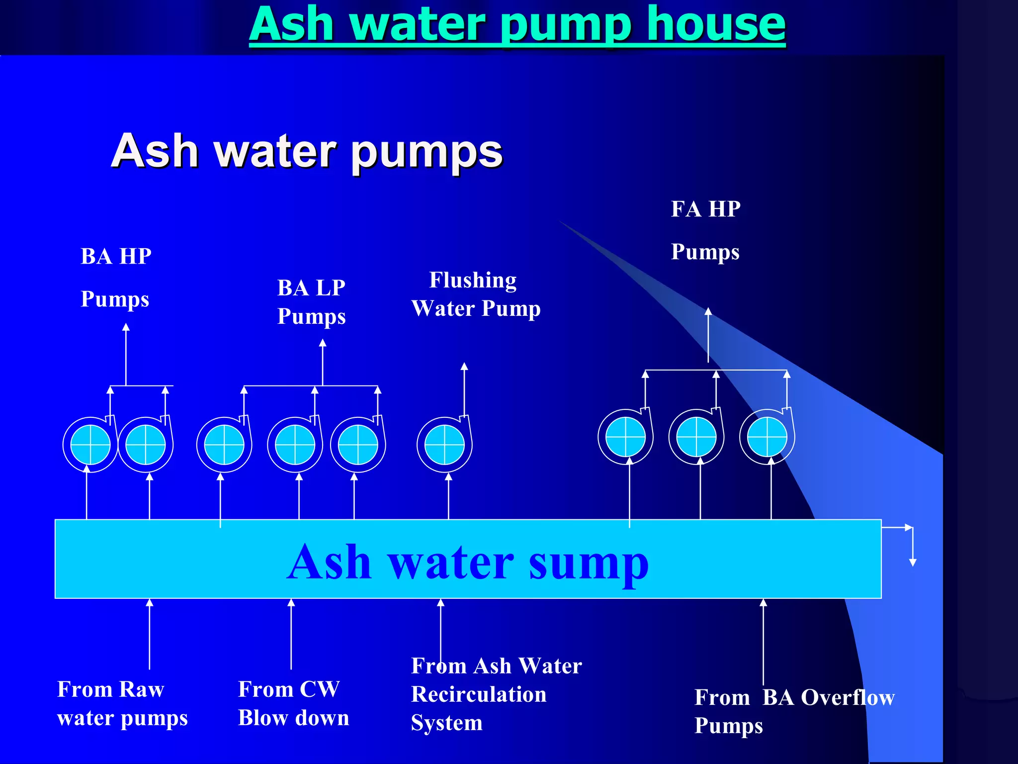
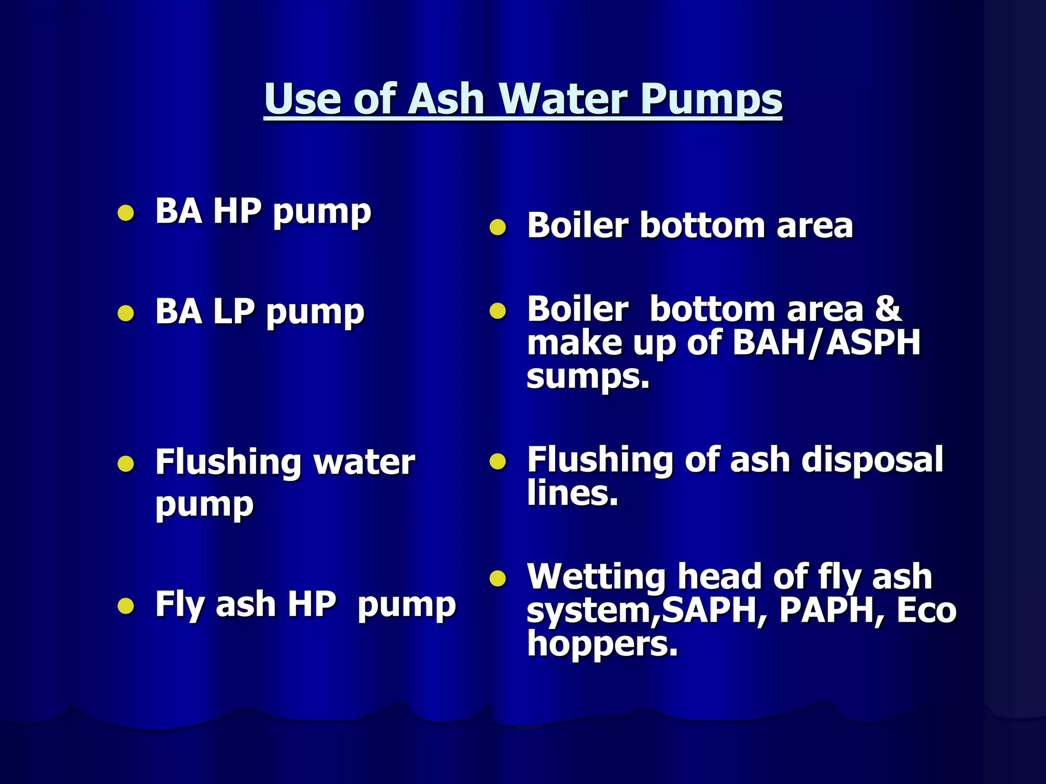
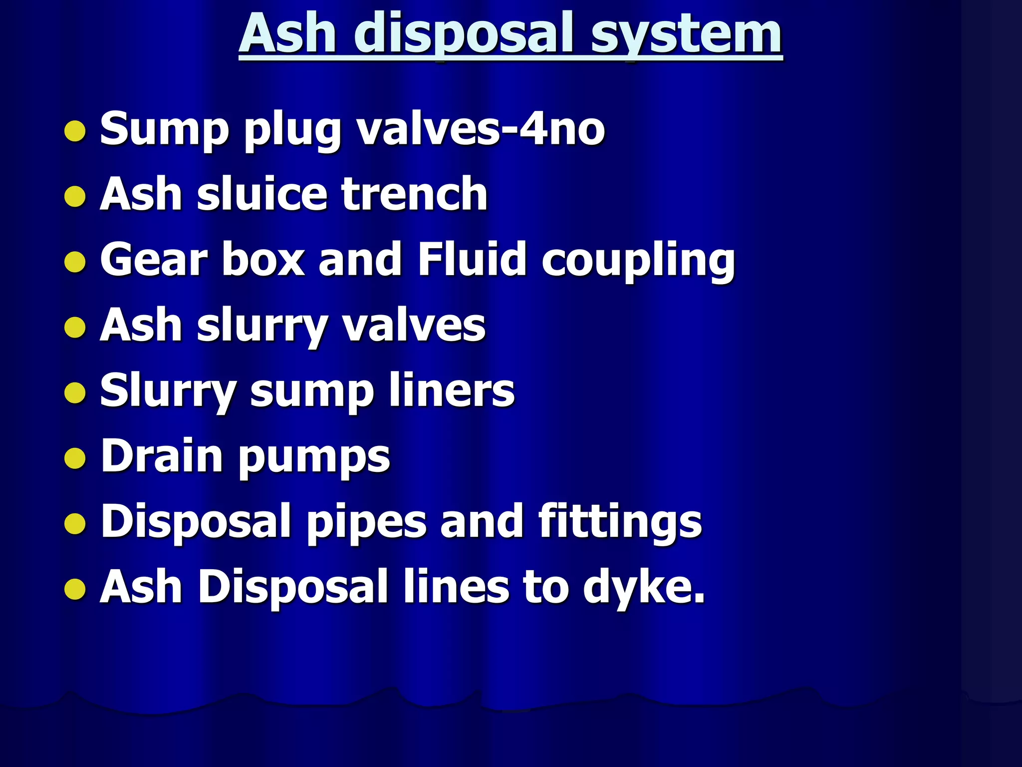
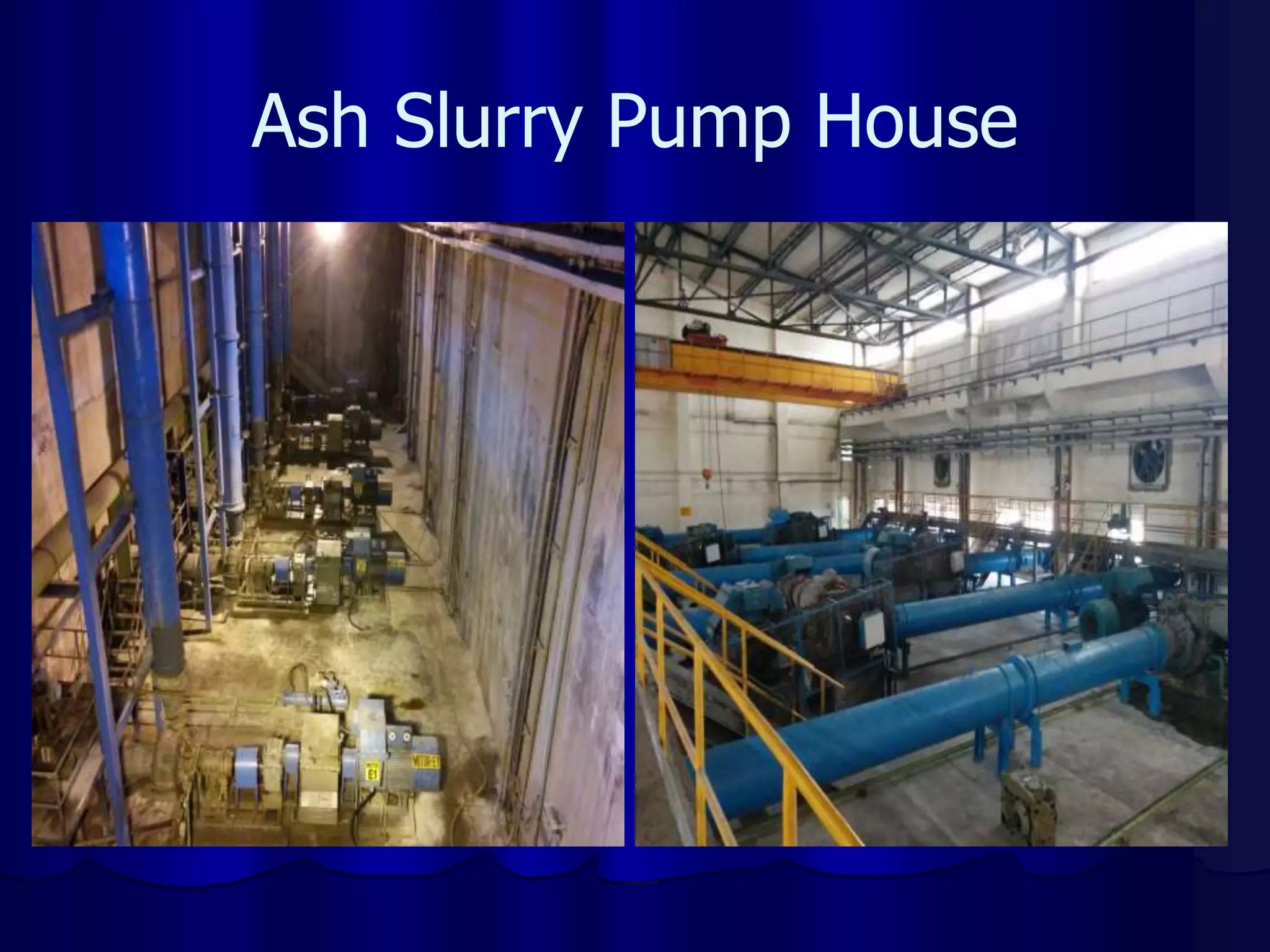
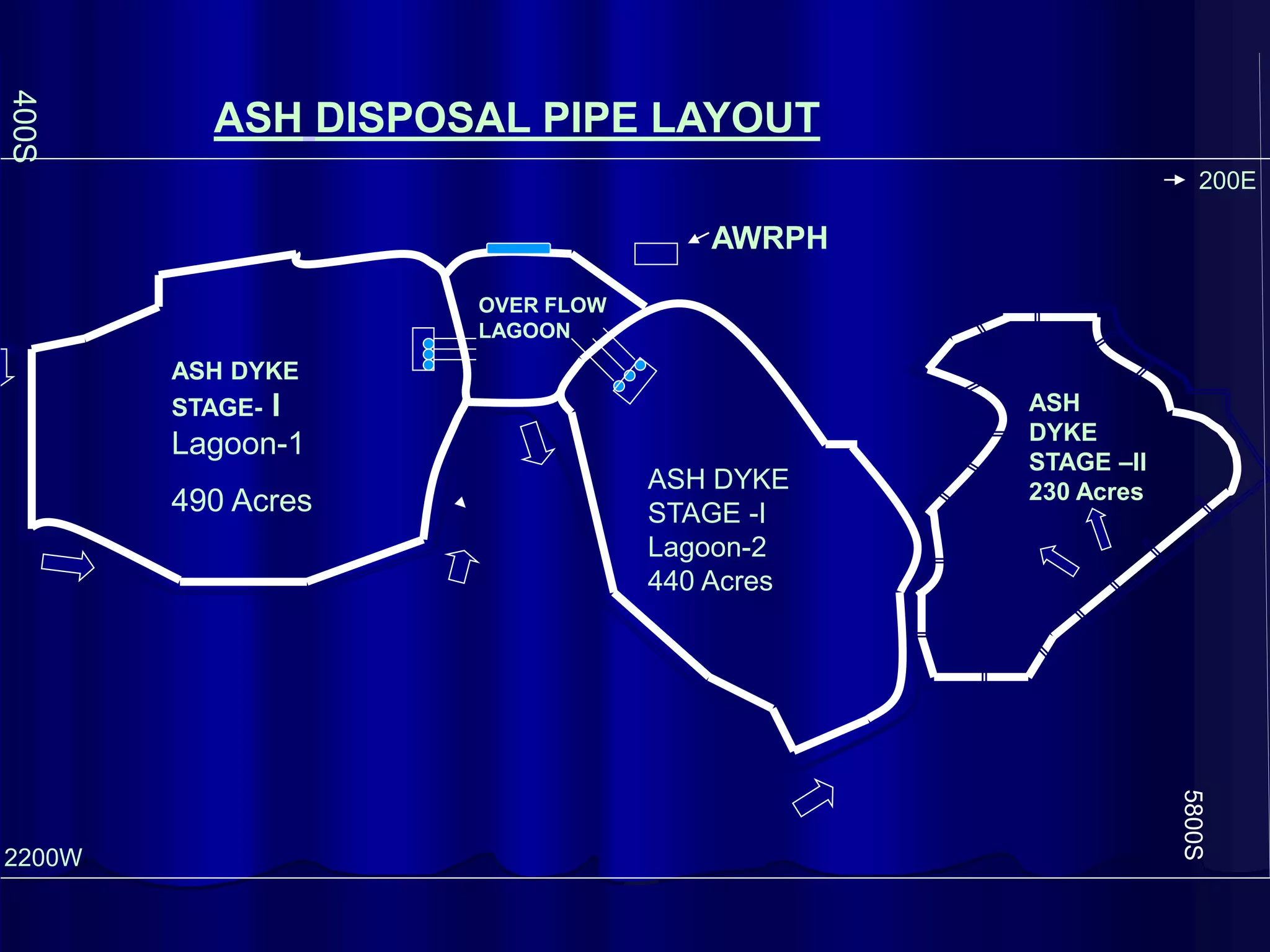
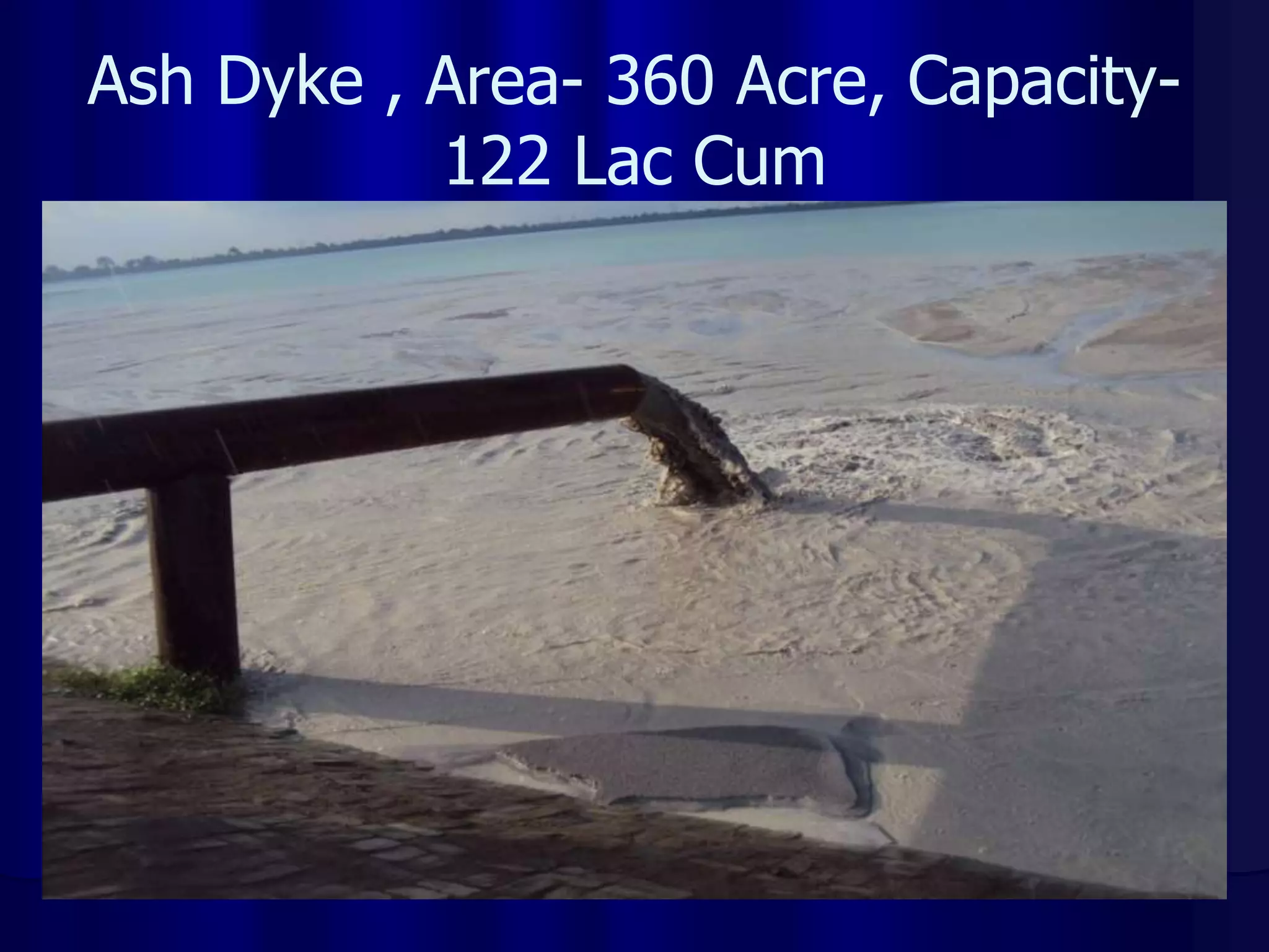
Ash handling system overview
 Bottom ash handling system.
 Fly ash handling system (both wet &
dry).
 Slurry handling system from slurry
pump house to ash dyke.
 Ash water system.
 Ash water recirculation system.
Types of ash Generated
 Fly ash ( approx 80%)
 Bottom ash ( approx 20%)
N.B:-- say 1 kg of coal contains 30 to 40 % of
ash. Let in a day of 24 hrs 20 MT of coal
burns then ash quantity = 20000x30 %=
6000 MT. So Bottom ash =6000x20%=1200
MT & Fly ash=6000x80%=4800 MT
System consists of ‘W’- type
water impounded hopper with
jet pumps for intermittent
removal of bottom ash. (WW)
Bottom ash system
Components of the system are :----
1. Water impounded ash hoppers
2. Hopper Feed gate- 4 no & 6 no
3. Clinker grinders-4 no & 6 no
4. Jet pumps
5. BA slurry line to ash slurry pump house
6. Slurry Transportation to ash dyke by
means of ash disposal pumps.
Intermittent type water impounded
hoppers & Jet pump system.
BOTTOM ASH HANDLING SYSTEM
W- Shaped Bottom Ash Hopper
Bottom Ash Hopper- Feed Gate
Arrangement
Feed Gate & Grinder Rolls
Flow diagram of hopper overflow water in jet
pump system
BA
HOPPER Over
Flow
Tank
Settling
Tank
Surge
Tank
Sludge to Ash
Slurry pump
House sump.
Over
Flow pumps
Sludge
Pump
To ash water
P/p house by
Gravity
Ash Removal System from
Economizer,PAPH,SAPH
Ash collected in Economizer,
PAPH & SAPH hoppers drop
continuously through Vertical
pipe connected to the
Flushing apparatus beneath
each of the hoppers
For the flushing apparatus
water is provided from FAHPs.
Fly ash handling system
The fly ash handling system
consists of two modes of
operation, Viz
1.Wet mode operation and
2.Dry mode operation.
Ash evacuation from ESP hoppers
1. Wet mode:--Ash evacuated from ESP
hoppers through vacuum pumps & fed
to wetting head (vacuum system) and
collector tank units where ash is mixed
with water & resultant slurry is
discharged to slurry trenches.
2. Dry mode :-- Ash evacuated from ESP
hoppers through vacuum pumps &
collected in Buffer hoppers & Air lock
tank, is transported to storage silo by
compressed air (pressure conveying
system) through pressure conveying pipe
lines.
ESP- Electrostatic Precipitator
ESP Internals
ESP Evacuation System
Components of wet fly ash
system
1.ESP hopper
2.Plate valve for isolation .
3.Material Handling Valve (MHV)
4.Piping up to wetting head
5.Wetting head
6.Air washer
7.Vacuum pump
8.Trench up to ash slurry pump house.
Flow diagram of wet fly ash system
ESP
Trench 2 ASPH
Air outlet
M H V
Plate valve
Vacuum pump
Wetting
head
Air washer
Air in
FLOW PATH OF WET MODE FLY ASH
ESP HOPPER
WETTING HEAD
AIR WASHER
DISCHARGE PIPE
SEAL BOX
FLY ASH SLURRY TRENCH
ASH SLURRY PUMP HOUSE
AIR TO
VACUUM
PUMP
Flow diagram of Dry fly ash system
Silo
TRUCK
Buffer
hopper ESP Hopper
Vacuum
pump
ALT
ALT
Air outlet
Bag filter
Bag filter
Air from TAC
Primary
& secondary
Collector
Flow path of dry mode fly ash
ESP Hopper
Buffer hopper
Air lock tank
Ash storage silo
Truck/volvo/wagons
Air to
Vacuum pump
Wet & Dry Mode
Ash water pump house
Ash water pumps
Ash water pumps
Ash water sump
BA HP
Pumps BA LP
Pumps
Flushing
Water Pump
FA HP
Pumps
From Raw
water pumps
From CW
Blow down
From Ash Water
Recirculation
System
From BA Overflow
Pumps
Ash water pumps
(located in ash water pump house)
1.Bottom ash HP water pumps- 2/2 no.
2.Bottom ash LP water pumps-3/5 no.
3.Flushing water pump-1/1 no.
4.Fly ash HP water pumps-3/5 no.
Use of Ash Water Pumps
 BA HP pump
 BA LP pump
 Flushing water
pump
 Fly ash HP pump
 Boiler bottom area
 Boiler bottom area &
make up of BAH/ASPH
sumps.
 Flushing of ash disposal
lines.
 Wetting head of fly ash
system,SAPH, PAPH, Eco
hoppers.
Ash Water Pump House
Ash disposal system
 Sump plug valves-4no
 Ash sluice trench
 Gear box and Fluid coupling
 Ash slurry valves
 Slurry sump liners
 Drain pumps
 Disposal pipes and fittings
 Ash Disposal lines to dyke.
Flushing Water Line
LP seal
water HP
Seal water
Ash Slurry Pump House
Ash Disposal Lines
AWRPH
ASH DYKE
STAGE- I
Lagoon-1
490 Acres
ASH DYKE
STAGE -I
Lagoon-2
440 Acres
OVER FLOW
LAGOON
ASH
DYKE
STAGE –II
230 Acres
ASH DISPOSAL PIPE LAYOUT
5800S
2200W
200E
400S
Ash Dyke , Area- 360 Acre, Capacity-
122 Lac Cum
Sprinklers System at Ash Dyke
Raising at Ash Dyke
Thank UA

Ash Handling in powerplants.ppt

  • 2.
    Ash handling systemoverview  Bottom ash handling system.  Fly ash handling system (both wet & dry).  Slurry handling system from slurry pump house to ash dyke.  Ash water system.  Ash water recirculation system.
  • 3.
    Types of ashGenerated  Fly ash ( approx 80%)  Bottom ash ( approx 20%) N.B:-- say 1 kg of coal contains 30 to 40 % of ash. Let in a day of 24 hrs 20 MT of coal burns then ash quantity = 20000x30 %= 6000 MT. So Bottom ash =6000x20%=1200 MT & Fly ash=6000x80%=4800 MT
  • 5.
    System consists of‘W’- type water impounded hopper with jet pumps for intermittent removal of bottom ash. (WW) Bottom ash system
  • 6.
    Components of thesystem are :---- 1. Water impounded ash hoppers 2. Hopper Feed gate- 4 no & 6 no 3. Clinker grinders-4 no & 6 no 4. Jet pumps 5. BA slurry line to ash slurry pump house 6. Slurry Transportation to ash dyke by means of ash disposal pumps. Intermittent type water impounded hoppers & Jet pump system.
  • 7.
  • 8.
    W- Shaped BottomAsh Hopper
  • 9.
    Bottom Ash Hopper-Feed Gate Arrangement
  • 10.
    Feed Gate &Grinder Rolls
  • 11.
    Flow diagram ofhopper overflow water in jet pump system BA HOPPER Over Flow Tank Settling Tank Surge Tank Sludge to Ash Slurry pump House sump. Over Flow pumps Sludge Pump To ash water P/p house by Gravity
  • 12.
    Ash Removal Systemfrom Economizer,PAPH,SAPH Ash collected in Economizer, PAPH & SAPH hoppers drop continuously through Vertical pipe connected to the Flushing apparatus beneath each of the hoppers For the flushing apparatus water is provided from FAHPs.
  • 13.
    Fly ash handlingsystem The fly ash handling system consists of two modes of operation, Viz 1.Wet mode operation and 2.Dry mode operation.
  • 14.
    Ash evacuation fromESP hoppers 1. Wet mode:--Ash evacuated from ESP hoppers through vacuum pumps & fed to wetting head (vacuum system) and collector tank units where ash is mixed with water & resultant slurry is discharged to slurry trenches. 2. Dry mode :-- Ash evacuated from ESP hoppers through vacuum pumps & collected in Buffer hoppers & Air lock tank, is transported to storage silo by compressed air (pressure conveying system) through pressure conveying pipe lines.
  • 15.
  • 16.
  • 17.
  • 18.
    Components of wetfly ash system 1.ESP hopper 2.Plate valve for isolation . 3.Material Handling Valve (MHV) 4.Piping up to wetting head 5.Wetting head 6.Air washer 7.Vacuum pump 8.Trench up to ash slurry pump house.
  • 19.
    Flow diagram ofwet fly ash system ESP Trench 2 ASPH Air outlet M H V Plate valve Vacuum pump Wetting head Air washer Air in
  • 20.
    FLOW PATH OFWET MODE FLY ASH ESP HOPPER WETTING HEAD AIR WASHER DISCHARGE PIPE SEAL BOX FLY ASH SLURRY TRENCH ASH SLURRY PUMP HOUSE AIR TO VACUUM PUMP
  • 21.
    Flow diagram ofDry fly ash system Silo TRUCK Buffer hopper ESP Hopper Vacuum pump ALT ALT Air outlet Bag filter Bag filter Air from TAC Primary & secondary Collector
  • 22.
    Flow path ofdry mode fly ash ESP Hopper Buffer hopper Air lock tank Ash storage silo Truck/volvo/wagons Air to Vacuum pump
  • 23.
  • 24.
    Ash water pumphouse Ash water pumps Ash water pumps Ash water sump BA HP Pumps BA LP Pumps Flushing Water Pump FA HP Pumps From Raw water pumps From CW Blow down From Ash Water Recirculation System From BA Overflow Pumps
  • 25.
    Ash water pumps (locatedin ash water pump house) 1.Bottom ash HP water pumps- 2/2 no. 2.Bottom ash LP water pumps-3/5 no. 3.Flushing water pump-1/1 no. 4.Fly ash HP water pumps-3/5 no.
  • 26.
    Use of AshWater Pumps  BA HP pump  BA LP pump  Flushing water pump  Fly ash HP pump  Boiler bottom area  Boiler bottom area & make up of BAH/ASPH sumps.  Flushing of ash disposal lines.  Wetting head of fly ash system,SAPH, PAPH, Eco hoppers.
  • 27.
  • 28.
    Ash disposal system Sump plug valves-4no  Ash sluice trench  Gear box and Fluid coupling  Ash slurry valves  Slurry sump liners  Drain pumps  Disposal pipes and fittings  Ash Disposal lines to dyke.
  • 29.
    Flushing Water Line LPseal water HP Seal water
  • 30.
  • 31.
  • 32.
    AWRPH ASH DYKE STAGE- I Lagoon-1 490Acres ASH DYKE STAGE -I Lagoon-2 440 Acres OVER FLOW LAGOON ASH DYKE STAGE –II 230 Acres ASH DISPOSAL PIPE LAYOUT 5800S 2200W 200E 400S
  • 33.
    Ash Dyke ,Area- 360 Acre, Capacity- 122 Lac Cum
  • 34.
  • 35.
  • 36.