The document provides information on CNC programming including:
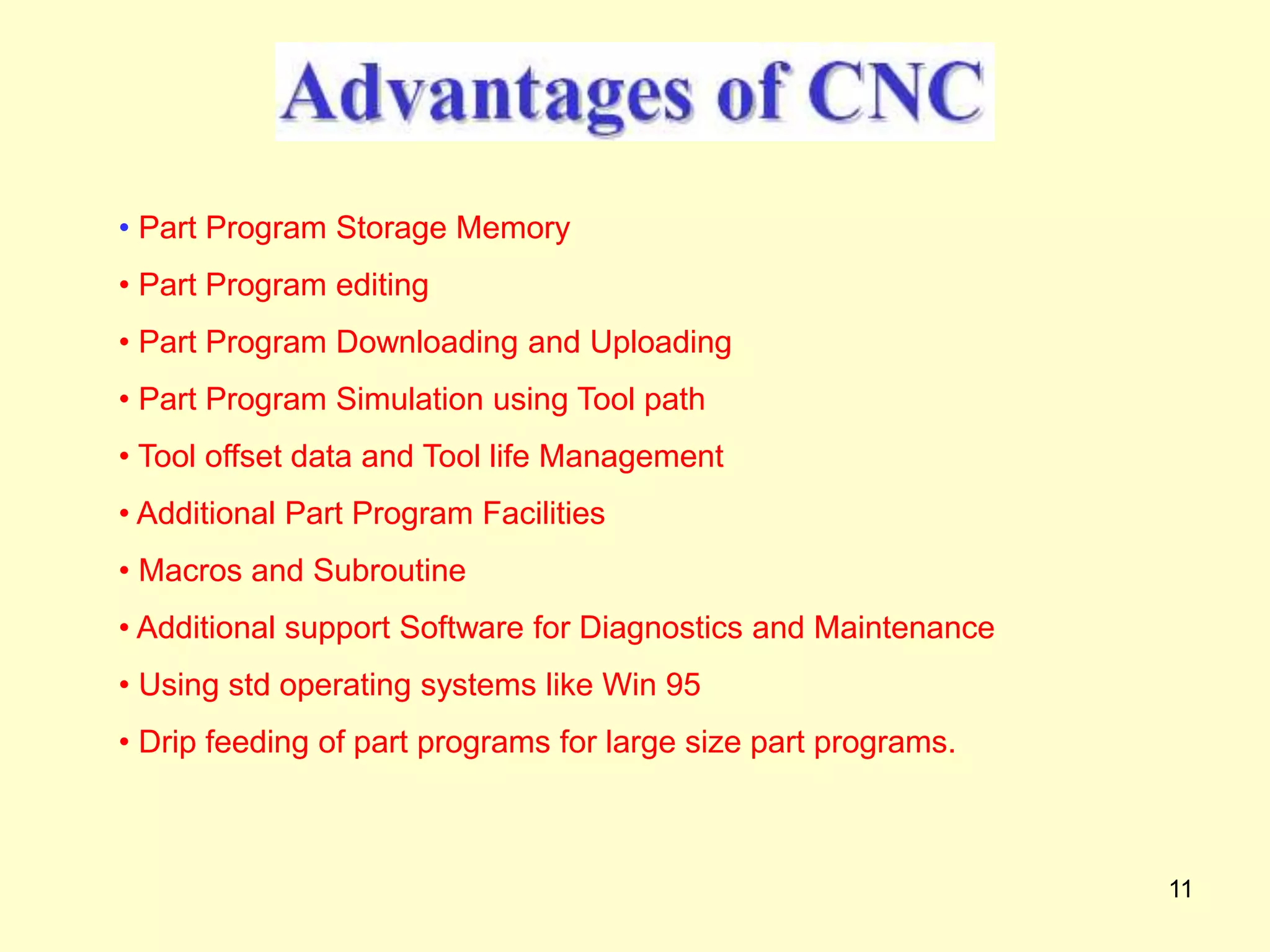
1) It describes the key components and functions of a CNC machine including part program storage, editing, downloading, simulation, tool and life management, and additional support software.
2) It explains common CNC programming concepts for lathes such as diameter vs radius programming, absolute vs incremental coordinate systems, common G and M codes, and the three parts of a CNC program - setup, material removal, and shutdown.
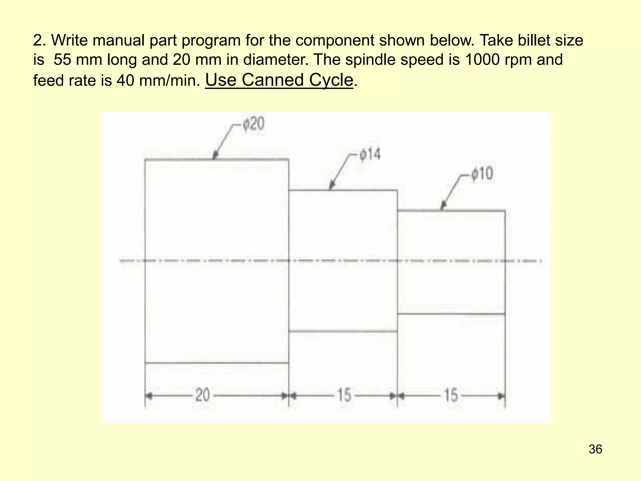
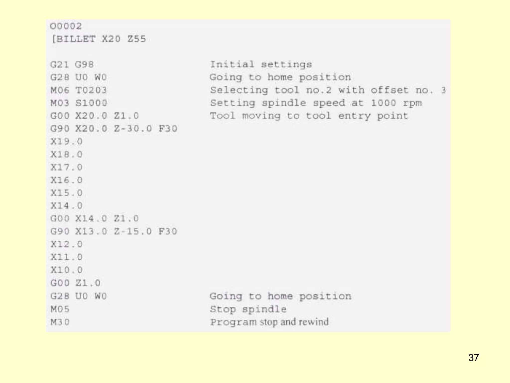
3) It provides examples of manual part programs using canned cycles for turning and facing operations to produce complex geometries with repetitive cuts in a concise program.


![28
%
O1212
[BILLET X Z ]
N10 G21 G99
N20 G28 U0 W0
N30 M06 T0101
N40 S1500
N50 M08
N60 M03
Program Setup](https://image.slidesharecdn.com/cnc-lathempp1-230801051528-ba4bf7f5/75/CNC-LATHE-MPP1-ppt-26-2048.jpg)


![[BILLET X25 Z60]
N10 G21 G40 G99;
N20 G28 U0 W0;
N30 M06 T0101;
N40 G50 S1500;
N50 G96 S150 M03;
N60 G00 X26 Z2;
N70 G71 U0.5 R0.5;
N80 G71 P90 Q150 U0.25 W0.15 F0.1;
N90 G01 X0;
N100 Z0;
N110 G03 X10 Z-5 R5 F0.25;
N120 G01 Z-15 F0.75;
N130 X20 Z-20;
N140 Z-30
N150 GO2 X25 Z-35 R5 F0.25;
N160 G70 P90 Q150 F0.01;
N170 G28 U0 W0;
N180 M30;
G71 – MULTIPLE TURNING](https://image.slidesharecdn.com/cnc-lathempp1-230801051528-ba4bf7f5/75/CNC-LATHE-MPP1-ppt-40-2048.jpg)

![G72 – MULTIPLE FACING
[BILLET X25 Z60]
N10 G21 G40 G99;
N20 G28 U0 W0;
N30 M06 T0101;
N40 G50 S1500;
N50 G96 S150 M03;
N60 G00 X26 Z2;
N70 G72 W0.5 R0.5;
N80 G72 P90 Q170 U0.25 W0.15 F0.1;
N90 G01 Z-20 F0.75;
N100 X25;
N110 X20;
N120 Z-18;
N130 X15 Z-15;
N140 Z-10
N150 GO2 X10 Z-5 R5 F0.25;
N160 G01 Z-3 F0.75;
N170 G01 X5 Z0;
N180 G70 P90 Q170 F0.01;
N190 G28 U0 W0;
N200 M30;](https://image.slidesharecdn.com/cnc-lathempp1-230801051528-ba4bf7f5/75/CNC-LATHE-MPP1-ppt-42-2048.jpg)