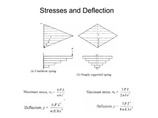
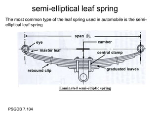
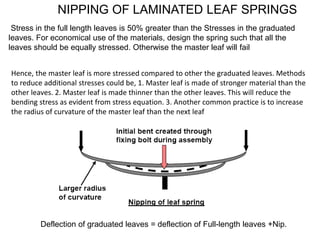
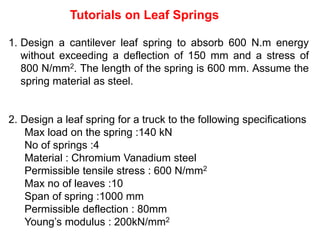
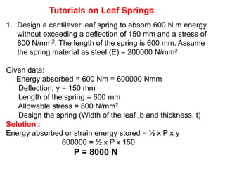
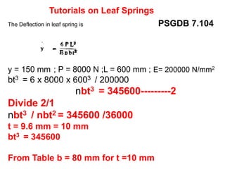
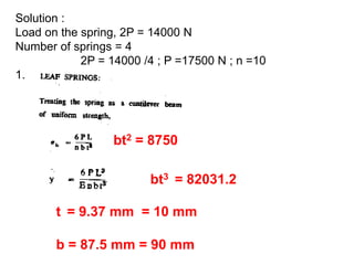
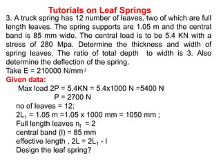
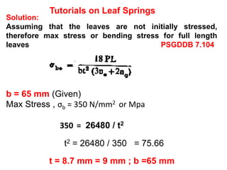
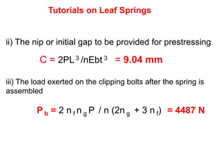
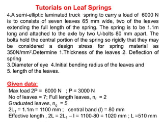
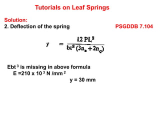
1. Introduction
Simply supported beams and cantilever beams may be used
as under a certain amount of load these beams get deflected
and thus absorb energy. These types of springs are
commonly called leaf spring or flat springs.
Springs may act as a structural member as well as an
energy-absorbing device. For example. An automobile leaf
spring may be designed not only to absorb road shocks, but
also to carry lateral loads, brake torque. Driving torque etc., a
leaf spring may have the form of cantilever beam as in fig. Or
it may have the beam of simply supported beam
Main stresses are tension on one side of the neutral axis and
Compression on the other.
7. This analysis shows that an automobile spring having length 2L loaded at the centre by
a load 2P may be treated as a beam of cantilever with load P of the end of span L.
The main drawback of the above spring is that the are stressed heavily at one specific
location and the other parts are stressed lightly. Therefore. These springs can be made
of uniform strength by keeping either a constant thickness or constant width generally,
the thickness of these springs is kept constant and the width is made variable as in fig
above
8. LAMINATED LEAF SPRINGS
In order to increase the load carrying capacity, number of flat plates are placed one
below the other as shown in below. The lengths of the plates are of gradually
decreasing at a constant rate. Such a spring is called the laminated leaf spring.
These types of spring are widely used in widely used in automobiles, railway wagons,
coaches etc.
10. The most common type of the leaf spring used in automobile is the semi-
elliptical leaf spring
semi-elliptical leaf spring
PSGDB 7.104
11. Hence, the master leaf is more stressed compared to other the graduated leaves. Methods
to reduce additional stresses could be, 1. Master leaf is made of stronger material than the
other leaves. 2. Master leaf is made thinner than the other leaves. This will reduce the
bending stress as evident from stress equation. 3. Another common practice is to increase
the radius of curvature of the master leaf than the next leaf
NIPPING OF LAMINATED LEAF SPRINGS
Stress in the full length leaves is 50% greater than the Stresses in the graduated
leaves. For economical use of the materials, design the spring such that all the
leaves should be equally stressed. Otherwise the master leaf will fail
Deflection of graduated leaves = deflection of Full-length leaves +Nip.
12.
13. Materials for leaf spring are not as good as that for the helical spring.
Plain carbon steel, Chromium vanadium steel, Chromium-
Nickel- Molybdenum steel, Silicon- manganese steel, are the
typical materials that are used in the design of leaf springs.
Materials for leaf spring
Standard sizes of leaf spring
Width (mm) : 25-80 mm in steps of 5mm
Thickness (mm) : 2-8 mm in steps of 1mm, 10-16 mm in steps
of 2mm
14. 1. Design a cantilever leaf spring to absorb 600 N.m energy
without exceeding a deflection of 150 mm and a stress of
800 N/mm2. The length of the spring is 600 mm. Assume the
spring material as steel.
2. Design a leaf spring for a truck to the following specifications
Max load on the spring :140 kN
No of springs :4
Material : Chromium Vanadium steel
Permissible tensile stress : 600 N/mm2
Max no of leaves :10
Span of spring :1000 mm
Permissible deflection : 80mm
Young’s modulus : 200kN/mm2
Tutorials on Leaf Springs
15. 1. Design a cantilever leaf spring to absorb 600 N.m energy
without exceeding a deflection of 150 mm and a stress of
800 N/mm2. The length of the spring is 600 mm. Assume
the spring material as steel (E) = 200000 N/mm2
Given data:
Energy absorbed = 600 Nm = 600000 Nmm
Deflection, y = 150 mm
Length of the spring = 600 mm
Allowable stress = 800 N/mm2
Design the spring (Width of the leaf ,b and thickness, t)
Solution :
Energy absorbed or strain energy stored = ½ x P x y
600000 = ½ x P x 150
P = 8000 N
Tutorials on Leaf Springs
16. The Maximum permissible stress in leaf spring is PSGDB 7.104
σb = 800 N/mm2 ; P = 8000 N ; L = 600 mm;
nbt2 = 6 x 8000 x 600 / 800
nbt2 = 36000------------1
Tutorials on Leaf Springs
17. The Deflection in leaf spring is PSGDB 7.104
y = 150 mm ; P = 8000 N ;L = 600 mm ; E= 200000 N/mm2
bt3 = 6 x 8000 x 6003 / 200000
nbt3 = 345600---------2
Divide 2/1
nbt3 / nbt2 = 345600 /36000
t = 9.6 mm = 10 mm
bt3 = 345600
From Table b = 80 mm for t =10 mm
Tutorials on Leaf Springs
18. 2. Design a leaf spring for a truck to the following
specifications:
Max load on the spring : 140 kN
No of springs : 4
Material : Chromium Vanadium steel
Permissible tensile stress : 600 N/mm2
Max no of leaves : 10
Span of spring : 1000 mm
Permissible deflection : 80mm
Young’s modulus : 200 kN/mm2
Given data:
For leaf spring Max load 2P = 140000 N;
no of springs = 4;
Span, 2L = 1000 mm ; L =500 mm
no of leaves = 10
Design the leaf spring?
Tutorials on Leaf Springs
19. Solution :
Load on the spring, 2P = 14000 N
Number of springs = 4
2P = 14000 /4 ; P =17500 N ; n =10
1.
bt2 = 8750
bt3 = 82031.2
t = 9.37 mm = 10 mm
b = 87.5 mm = 90 mm
20. 3. A truck spring has 12 number of leaves, two of which are full
length leaves. The spring supports are 1.05 m and the central
band is 85 mm wide. The central load is to be 5.4 KN with a
stress of 280 Mpa. Determine the thickness and width of
spring leaves. The ratio of total depth to width is 3. Also
determine the deflection of the spring.
Take E = 210000 N/mm 2
Given data:
Max load 2P = 5.4KN = 5.4x1000 N =5400 N
P = 2700 N
no of leaves = 12;
2L1 = 1.05 m =1.05 x 1000 mm = 1050 mm ;
Full length leaves nf = 2
central band (l) = 85 mm
effective length , 2L = 2L1 - l
Design the leaf spring?
Tutorials on Leaf Springs
21. Solution:
Thickness and width of spring leaves (t & b):
The ratio of total depth to width is 3, n x t / b =3
n=12 ; 12t/b =3; 12t =3b ; b =4t
effective length , 2L = 2L1 – l=1050-85 =965 mm
L = 965/2 =482.5 mm
No of leaves n = nf + ng ; n =12 ; nf = 2 ; ng = 12-2 =10
Tutorials on Leaf Springs
22. Solution:
Assuming that the leaves are not initially stressed,
therefore max stress or bending stress for full length
leaves PSGDDB 7.104
Max Stress , σb = 280 N/mm2 or Mpa
σbe = 225476 / t3
t3 = 225476 / 280 = 805.3
t = 9.3 mm = 10 mm ; b =4t ; b =40 mm
Tutorials on Leaf Springs
23. Solution:
Deflection of the spring PSGDDB 7.104
Ebt 3 is missing in above formula
E = 210000 N/mm 2 (Given)
y = 16.7 mm
Tutorials on Leaf Springs
24. 4. A semi-elliptic spring has an overall length of 1m and sustains a
load of 70 kN at its center. The spring has 3 extra full length leaves
and 15 graduated leaves with a central band of 100 mm width. All
the leaves are to be stressed equally without exceeding 400 N/mm2
when fully loaded. The total depth of spring is twice the width. If the
young's modulus is 210 kN/mm2, determine
i) The thickness and width of leaves.
ii) The nip or initial gap to be provided for prestressing.
iii) The load exerted on the clipping bolts after the spring is
assembled
Given data:
Max load 2P = 70KN = 70x1000 N =70000 N
P = 35000 N
no of leaves = 18;
2L1 = 1m = 1000 mm ;
Full length leaves, nf = 3 ; Graduated leaves, ng = 15
central band (l) = 100 mm
effective length , 2L = 2L1 – l = 1000-100 = 900 mm ; L =450 mm
Tutorials on Leaf Springs
25. Solution:
The thickness and width of leaves
Assuming that the leaves are stressed, therefore max
stress or bending stress PSGDDB 7.104
The ratio of total depth to width is 2, n x t / b =2
n = nf + ng = 18 ; 18 t / b =2; 18 t =2 b ; b = 9t
Max Stress , σb = 400 N/mm2 or Mpa
400 = 583000 / t3
t3 = 225476 / 400 = 1458
t = 11.3 mm = 12 mm ; b =9t ; b =108 mm
Tutorials on Leaf Springs
26. Solution:
Assuming that the leaves are not initially stressed,
therefore max stress or bending stress for full length
leaves PSGDDB 7.104
b = 65 mm (Given)
Max Stress , σb = 350 N/mm2 or Mpa
350 = 26480 / t2
t2 = 26480 / 350 = 75.66
t = 8.7 mm = 9 mm ; b =65 mm
Tutorials on Leaf Springs
27. ii) The nip or initial gap to be provided for prestressing.
C = 2PL3 /nEbt 3 = 9.04 mm
iii) The load exerted on the clipping bolts after the spring is
assembled
P b = 2 n f n g P / n (2n g + 3 n f) = 4487 N
Tutorials on Leaf Springs
28. 4.A semi-elliptic laminated truck spring to carry a load of 6000 N
is to consists of seven leaves 65 mm wide, two of the leaves
extending the full length of the spring. The spring is to be 1.1m
long and attached to the axle by two U-bolts 80 mm apart. The
bolts hold the central portion of the spring so rigidly that they may
be considered a design stress for spring material as
350N/mm2.Determine 1.Thickness of the leaves 2. Deflection of
spring
3.Diameter of eye 4.Initial bending radius of the leaves and
5. length of the leaves.
Given data:
Max load 2P = 6000 N ; P = 3000 N
No of leaves = 7; Full length leaves, nf = 2
Graduated leaves, ng = 5
2L1 = 1.1m = 1100 mm ; central band (l) = 80 mm
Effective length , 2L = 2L1 – l = 1100-80 = 1020 mm ; L =510 mm
Tutorials on Leaf Springs
29. Solution:
1.Thickness of the leaves
Assuming that the leaves are not initially stressed,
therefore max stress or bending stress for full length
leaves PSGDDB 7.104
b = 65 mm (Given)
Max Stress , σb = 350 N/mm2 or Mpa
350 = 26480 / t2
t2 = 26480 / 350 = 75.66
t = 8.7 mm = 9 mm ; b =65 mm
Tutorials on Leaf Springs
30. Solution:
2. Deflection of the spring PSGDDB 7.104
Ebt 3 is missing in above formula
E =210 x 10 3 N /mm 2
y = 30 mm
Tutorials on Leaf Springs
31. Solution:
3. Initial bending radius of the leaves PSGDDB 7.104
y(2R-y) = (L1 )2
R = 5056.5 mm
Tutorials on Leaf Springs