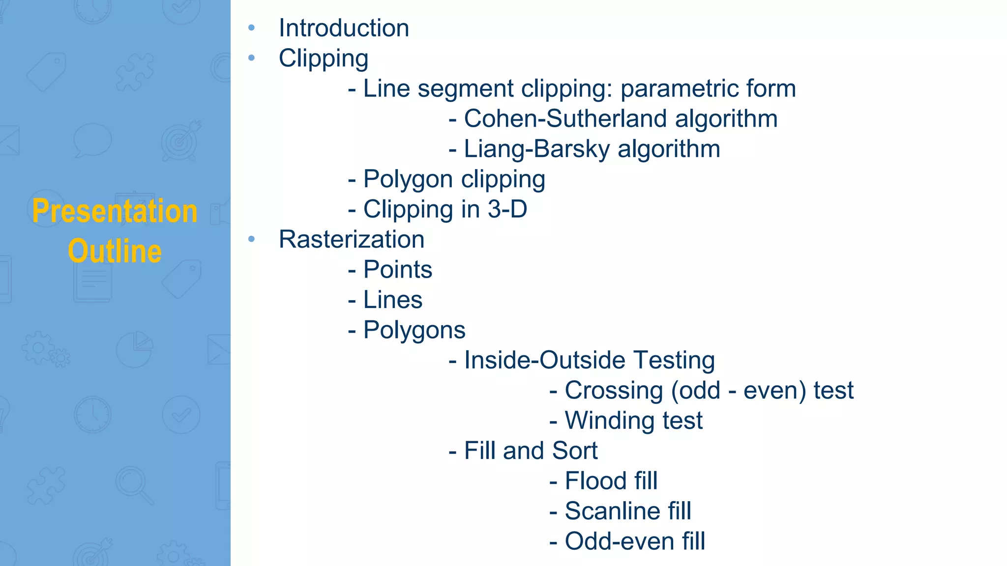
Chapter 5
Clipping & Rasterization
by
Ahmed Daoud
Presentation
Outline
• Introduction
• Clipping
- Line segment clipping: parametric form
- Cohen-Sutherland algorithm
- Liang-Barsky algorithm
- Polygon clipping
- Clipping in 3-D
• Rasterization
- Points
- Lines
- Polygons
- Inside-Outside Testing
- Crossing (odd - even) test
- Winding test
- Fill and Sort
- Flood fill
- Scanline fill
- Odd-even fill
Introduction
Introduction
• At end of the geometric pipeline, vertices have been
assembled into primitives (lines, planes, etc.)
• Must clip out primitives that are outside the view
volume
• Algorithms based on representing primitives by lists of
vertices
• Must find which pixels can be affected by each
primitive
Fragment generation
Rasterization or scan conversion
High-Level view of the graphics process
Application
program
Graphics
system
Frame
buffer
Vertices Pixels
• Two main steps:
- We must pass every geometric object through the system.
- we must assign a color to every pixel in the color buffer
that is displayed
Clipping
What is clipping?
• Clipping is the process of eliminating objects that lie
outside the viewing volume and thus cannot be
visible in the image.
• Clipping is the process of determining which
primitives, or part of primitives, fit within the clipping
or view volume defined by the application program
 2D against clipping window
 3D against clipping volume
 Easy for line segments polygons
 Hard for curves and text
- Convert to lines and polygons first
Line
segment
clipping
▸ A clipper decide which primitives, or part of
primitives, can possibly appear on the display and
be passed on to the rasterizer
▸ Primitives that fit within the specified view volume
pass through the clipper or are accepted
▸ Primitives that cannot appear on the display are
eliminated or rejected
Line
segment
clipping
Cohen-Sutherland algorithm
2D clipping
• A point (x, y) is coded according to its position with respect to the viewport boundaries with a
4-bit code called outcode
Cases of
outcodes
in Cohen-
Sutherland
algorithm
• Let the two endpoints of a line segment be (x1, y1) and (x2, y2)
and o1 = outcode(x1, y1) , o2 = outcode (x2, y2)
• There are 4 cases:
Case 1: o1 = o2 = 0
Both endpoints inside window  no clipping
Case 2: o1 != 0, o2 = 0 or o1 = 0, o2 != 0
One endpoint inside window  clip one end (given by outcode != 0)
Test against each edge in a fixed order and clip
Code intersection point, repeat process to see if 2nd clipping required
Case 3: o1 & o2 != 0 (Bitwise AND)
If endpoints are both on same side of a window edge discard.
Case 4: o1 & o2 = 0 (Bitwise AND)
The endpoints are both outside but across adjacent edges:
a) may intersect the extensions  line segment outside the window
b) may intersect the edges  line segment must be clipped at both
adjacent edges
Line segments and the parametric form
Line segments can be specified in many ways:
• 1) Slope and y intercept
y = m x + c m = slope Will not work for vertical line (m = ∞)
• 2) One point (x1, y1) and slope
y = y1 + m (x – x1) Will not work for vertical line (m = ∞)
• 3) Two points
(y – y2) / (x – x2) = (y – y1) / (x – x1) Will not work if x = x1 or x2
• 4) Parametric form: 2 points and a parameter
x = x1 u + x2 (1-u) y = y1 u + y2 (1-u) Will work for any line.
Furthermore, says that
• 0 <= u <= 1 (x, y) lies between (x1, y1) and (x2, y2)
• u < 0 (x, y) lies outside on the side of (x1, y1)
• u > 1 (x, y) lies outside on the side of (x2, y2)
Line
segment
clipping
Liang-Barsky algorithm
▸Consider the parametric form of a line
segment
p(a) = (1-a)p1+ ap2 1 ≥ a ≥ 0
Liang-
Barsky
algorithm
▸ We can distinguish between the cases by looking at
the ordering of the values of a where the line
determined by the line segment crosses the lines that
determine the window
Polygon
clipping
▸Polygons need to be clipped against a rectangular (usually)
window.
▸Not as simple as line segment clipping
Clipping a line segment yields at most one line segment
Clipping a polygon can yield multiple polygons
▸ Sometimes clipped against non-rectangular windows
▸Consider rectangular windows:
Convex polygon  Clipped convex polygon (only one)
Concave polygon  May result in more than one
clipped piece
Strategies
1. Brute force
2. Triangulation = Replace nonconvex with convex pieces
(Tessellation)
3. Clipping as a Black Box  Pipeline approach
1. Brute Force Straightforward algorithm: Apply Cohen-Surtherland or Liang-Barsky edge by edge
2. Tessellation and
Convexity
▸Replace nonconvex (concave) polygons with a set of triangular
polygons (a tessellation)
▸Also makes fill easier
3. Black box
approach: clipping
pipeline
▸Can consider line segment clipping as a process that takes in two
vertices and produces either no vertices or the vertices of a clipped line
segment  Clipping against each side of window is independent of
other sides
▸Can use four independent clippers in a pipeline
Exmaple: Black Box:
Line clipping
▸Polygon can be clipped successively against the boundaries of the window edge by
edge
Clipping
in 3-D
▸Cohen Sutherland in 3D
▸Use 6-bit outcodes
▸When needed, clip
line segment
against planes
Clipping
in 3-D
▸Cohen Sutherland in 3D
Rasterization
What is
Rasterization?
• This is (almost) the last stage in the viewing
pipeline
• Produces fragments from the remaining objects
and them into discrete representation, in the
frame buffer, for display
• The resulting objects from the previous
transformations are essentially polygons which
must now be rasterized, that is, they must be
converted to addresses in the buffer and the
contents of the address loaded with
color/intensity information.
• Sometimes called scan conversion
Rasterization
▸This scan conversion can be considered from simple
to complicated
▸Scan conversion of :
▸Points
▸Lines
▸Polygons
Points
• The color buffer is n x m array of pixels
• The address is now the address of a pixel address
(ix, iy)
• A color or intensity is now stored in the buffer
location corresponding to (ix, iy)  write_pixel (ix, iy,
value);
Lines
• Line L is given by the points in the segment (ix1, iy1)
- (ix2, iy2)
• These points must be scan converted 
rounded/truncated to integer addresses on the
screen.
• Line scan conversion algorithms
• DDA algorithm
• Bresenham algorithm
Lines
• Points on line are obtained from the differential
equation dy/dx = m
• where m = (y2 – y1) / (x2 – x1) = Δy / Δx 0 ≤ m ≤ 1
▸Coordinates are integers  pixels generated
successively with increments of 1 in the x variable.
▸Change in y = Δy = m Δx
▸Δx always 1  Δy = m
for (ix=x; ix <= ix2; ix++)
{
y += m;
write_pixel(x, round (y),line_color);
}
Ploygons
 Inside-Outside Testing
- Crossing test = Odd-even test
- Winding test (for non-simple polygons)
 Fill and Sort
- Flood fill
- Scanline fill
- Odd-even fill
Inside-Outside
Testing
1) Crossing test = Odd-even test
- Let p be a point inside a simple polygon any ray from
p must cross an odd number of edges of the polygon
- Let p be a point outside a simple polygon any ray from
p must cross an even number of edges of the polygon
2) Winding test (for non-simple polygons)
- we must decide how to determine whether a given point
is inside or outside of the polygon.
- Winding Number Count clockwise encirclements of
point:
odd  inside even  outside
Winding test
Example
Flood fill
▸Fill can be done recursively from an initial point, seed
point, located inside the polygon (WHITE)
▸Scan convert edges into buffer in edge/inside color
(BLACK)
void flood_fill(int x, int y)
{
if(read_pixel(x,y)= = WHITE) {
write_pixel(x,y,BLACK);
flood_fill(x-1, y);
flood_fill(x+1, y);
flood_fill(x, y+1);
flood_fill(x, y-1);
}
}
Hidden-Surface Removal
What is hidden-
surface removal?
• Determines which fragments correspond to objects
that are visible.
• Those that are in the view volume and are not
blocked from view by other objects closer to the
camera.
Clipping & Rasterization

Clipping & Rasterization

  • 1.
    Chapter 5 Clipping &Rasterization by Ahmed Daoud
  • 2.
    Presentation Outline • Introduction • Clipping -Line segment clipping: parametric form - Cohen-Sutherland algorithm - Liang-Barsky algorithm - Polygon clipping - Clipping in 3-D • Rasterization - Points - Lines - Polygons - Inside-Outside Testing - Crossing (odd - even) test - Winding test - Fill and Sort - Flood fill - Scanline fill - Odd-even fill
  • 3.
  • 4.
    Introduction • At endof the geometric pipeline, vertices have been assembled into primitives (lines, planes, etc.) • Must clip out primitives that are outside the view volume • Algorithms based on representing primitives by lists of vertices • Must find which pixels can be affected by each primitive Fragment generation Rasterization or scan conversion
  • 5.
    High-Level view ofthe graphics process Application program Graphics system Frame buffer Vertices Pixels • Two main steps: - We must pass every geometric object through the system. - we must assign a color to every pixel in the color buffer that is displayed
  • 6.
  • 7.
    What is clipping? •Clipping is the process of eliminating objects that lie outside the viewing volume and thus cannot be visible in the image. • Clipping is the process of determining which primitives, or part of primitives, fit within the clipping or view volume defined by the application program
  • 8.
     2D againstclipping window  3D against clipping volume  Easy for line segments polygons  Hard for curves and text - Convert to lines and polygons first
  • 9.
    Line segment clipping ▸ A clipperdecide which primitives, or part of primitives, can possibly appear on the display and be passed on to the rasterizer ▸ Primitives that fit within the specified view volume pass through the clipper or are accepted ▸ Primitives that cannot appear on the display are eliminated or rejected
  • 10.
  • 11.
    • A point(x, y) is coded according to its position with respect to the viewport boundaries with a 4-bit code called outcode
  • 13.
  • 14.
    • Let thetwo endpoints of a line segment be (x1, y1) and (x2, y2) and o1 = outcode(x1, y1) , o2 = outcode (x2, y2) • There are 4 cases: Case 1: o1 = o2 = 0 Both endpoints inside window  no clipping Case 2: o1 != 0, o2 = 0 or o1 = 0, o2 != 0 One endpoint inside window  clip one end (given by outcode != 0) Test against each edge in a fixed order and clip Code intersection point, repeat process to see if 2nd clipping required Case 3: o1 & o2 != 0 (Bitwise AND) If endpoints are both on same side of a window edge discard. Case 4: o1 & o2 = 0 (Bitwise AND) The endpoints are both outside but across adjacent edges: a) may intersect the extensions  line segment outside the window b) may intersect the edges  line segment must be clipped at both adjacent edges
  • 15.
    Line segments andthe parametric form Line segments can be specified in many ways: • 1) Slope and y intercept y = m x + c m = slope Will not work for vertical line (m = ∞) • 2) One point (x1, y1) and slope y = y1 + m (x – x1) Will not work for vertical line (m = ∞) • 3) Two points (y – y2) / (x – x2) = (y – y1) / (x – x1) Will not work if x = x1 or x2 • 4) Parametric form: 2 points and a parameter x = x1 u + x2 (1-u) y = y1 u + y2 (1-u) Will work for any line. Furthermore, says that • 0 <= u <= 1 (x, y) lies between (x1, y1) and (x2, y2) • u < 0 (x, y) lies outside on the side of (x1, y1) • u > 1 (x, y) lies outside on the side of (x2, y2)
  • 16.
    Line segment clipping Liang-Barsky algorithm ▸Consider theparametric form of a line segment p(a) = (1-a)p1+ ap2 1 ≥ a ≥ 0
  • 17.
    Liang- Barsky algorithm ▸ We candistinguish between the cases by looking at the ordering of the values of a where the line determined by the line segment crosses the lines that determine the window
  • 18.
    Polygon clipping ▸Polygons need tobe clipped against a rectangular (usually) window. ▸Not as simple as line segment clipping Clipping a line segment yields at most one line segment Clipping a polygon can yield multiple polygons ▸ Sometimes clipped against non-rectangular windows ▸Consider rectangular windows: Convex polygon  Clipped convex polygon (only one) Concave polygon  May result in more than one clipped piece
  • 19.
    Strategies 1. Brute force 2.Triangulation = Replace nonconvex with convex pieces (Tessellation) 3. Clipping as a Black Box  Pipeline approach 1. Brute Force Straightforward algorithm: Apply Cohen-Surtherland or Liang-Barsky edge by edge
  • 20.
    2. Tessellation and Convexity ▸Replacenonconvex (concave) polygons with a set of triangular polygons (a tessellation) ▸Also makes fill easier
  • 21.
    3. Black box approach:clipping pipeline ▸Can consider line segment clipping as a process that takes in two vertices and produces either no vertices or the vertices of a clipped line segment  Clipping against each side of window is independent of other sides ▸Can use four independent clippers in a pipeline
  • 22.
  • 23.
    ▸Polygon can beclipped successively against the boundaries of the window edge by edge
  • 24.
    Clipping in 3-D ▸Cohen Sutherlandin 3D ▸Use 6-bit outcodes ▸When needed, clip line segment against planes
  • 25.
  • 26.
  • 27.
    What is Rasterization? • Thisis (almost) the last stage in the viewing pipeline • Produces fragments from the remaining objects and them into discrete representation, in the frame buffer, for display • The resulting objects from the previous transformations are essentially polygons which must now be rasterized, that is, they must be converted to addresses in the buffer and the contents of the address loaded with color/intensity information. • Sometimes called scan conversion
  • 28.
    Rasterization ▸This scan conversioncan be considered from simple to complicated ▸Scan conversion of : ▸Points ▸Lines ▸Polygons
  • 29.
    Points • The colorbuffer is n x m array of pixels • The address is now the address of a pixel address (ix, iy) • A color or intensity is now stored in the buffer location corresponding to (ix, iy)  write_pixel (ix, iy, value);
  • 30.
    Lines • Line Lis given by the points in the segment (ix1, iy1) - (ix2, iy2) • These points must be scan converted  rounded/truncated to integer addresses on the screen. • Line scan conversion algorithms • DDA algorithm • Bresenham algorithm
  • 31.
    Lines • Points online are obtained from the differential equation dy/dx = m • where m = (y2 – y1) / (x2 – x1) = Δy / Δx 0 ≤ m ≤ 1 ▸Coordinates are integers  pixels generated successively with increments of 1 in the x variable. ▸Change in y = Δy = m Δx ▸Δx always 1  Δy = m for (ix=x; ix <= ix2; ix++) { y += m; write_pixel(x, round (y),line_color); }
  • 32.
    Ploygons  Inside-Outside Testing -Crossing test = Odd-even test - Winding test (for non-simple polygons)  Fill and Sort - Flood fill - Scanline fill - Odd-even fill
  • 33.
    Inside-Outside Testing 1) Crossing test= Odd-even test - Let p be a point inside a simple polygon any ray from p must cross an odd number of edges of the polygon - Let p be a point outside a simple polygon any ray from p must cross an even number of edges of the polygon 2) Winding test (for non-simple polygons) - we must decide how to determine whether a given point is inside or outside of the polygon. - Winding Number Count clockwise encirclements of point: odd  inside even  outside
  • 34.
  • 35.
    Flood fill ▸Fill canbe done recursively from an initial point, seed point, located inside the polygon (WHITE) ▸Scan convert edges into buffer in edge/inside color (BLACK) void flood_fill(int x, int y) { if(read_pixel(x,y)= = WHITE) { write_pixel(x,y,BLACK); flood_fill(x-1, y); flood_fill(x+1, y); flood_fill(x, y+1); flood_fill(x, y-1); } }
  • 36.
  • 37.
    What is hidden- surfaceremoval? • Determines which fragments correspond to objects that are visible. • Those that are in the view volume and are not blocked from view by other objects closer to the camera.

Editor's Notes

  • #3 Hidden-Surface Removal
  • #5 Modeling = Process of creating a set of objects making up a scene or a large object
  • #6 Geometric object = a set of vertices
  • #18  a = (ymax – y1) / (y2 – y1)