Downloaded 113 times


![Particles
Control Action
1. Design airflow path to shield humans
from surroundings
2. Use of air showers [to continually wash
occupants with clean air]
3. Using hard-surfaced, non-porous materials
such as polyvinyl panels, epoxy painted walls,
and glass board ceilings
4. Proper gowning procedures, head wear
1. INTERNAL SOURCES](https://image.slidesharecdn.com/cleanroomacompendiumaccordingtoapprovedguidelines-170606080230/75/Clean-Room-A-compendium-according-to-approved-guidelines-25-2048.jpg)


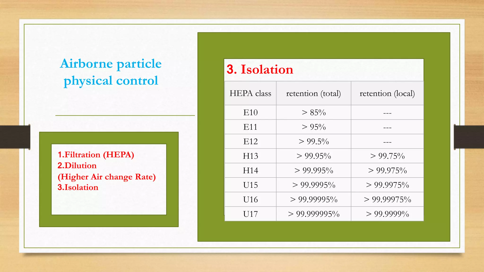


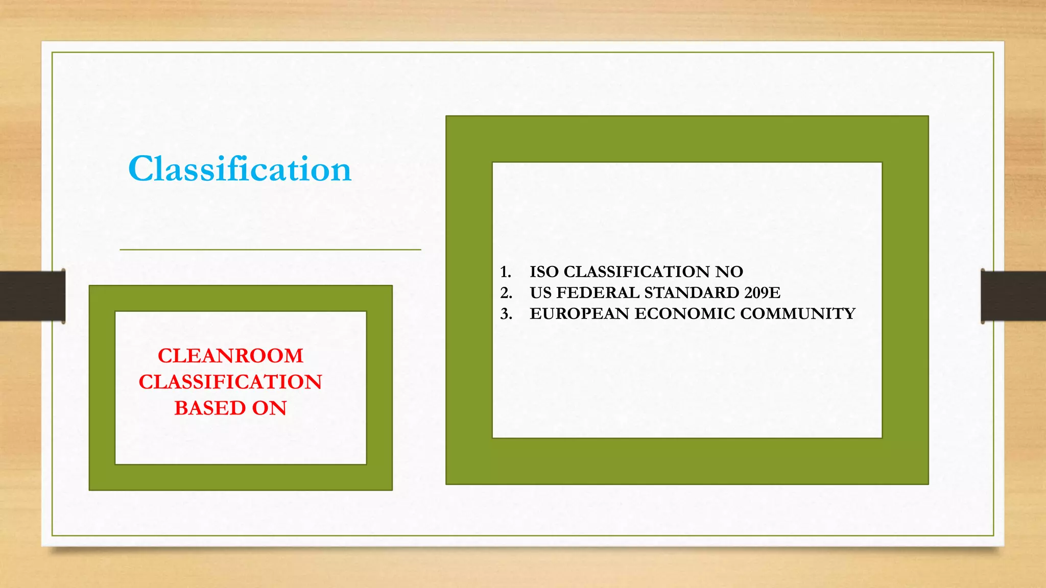
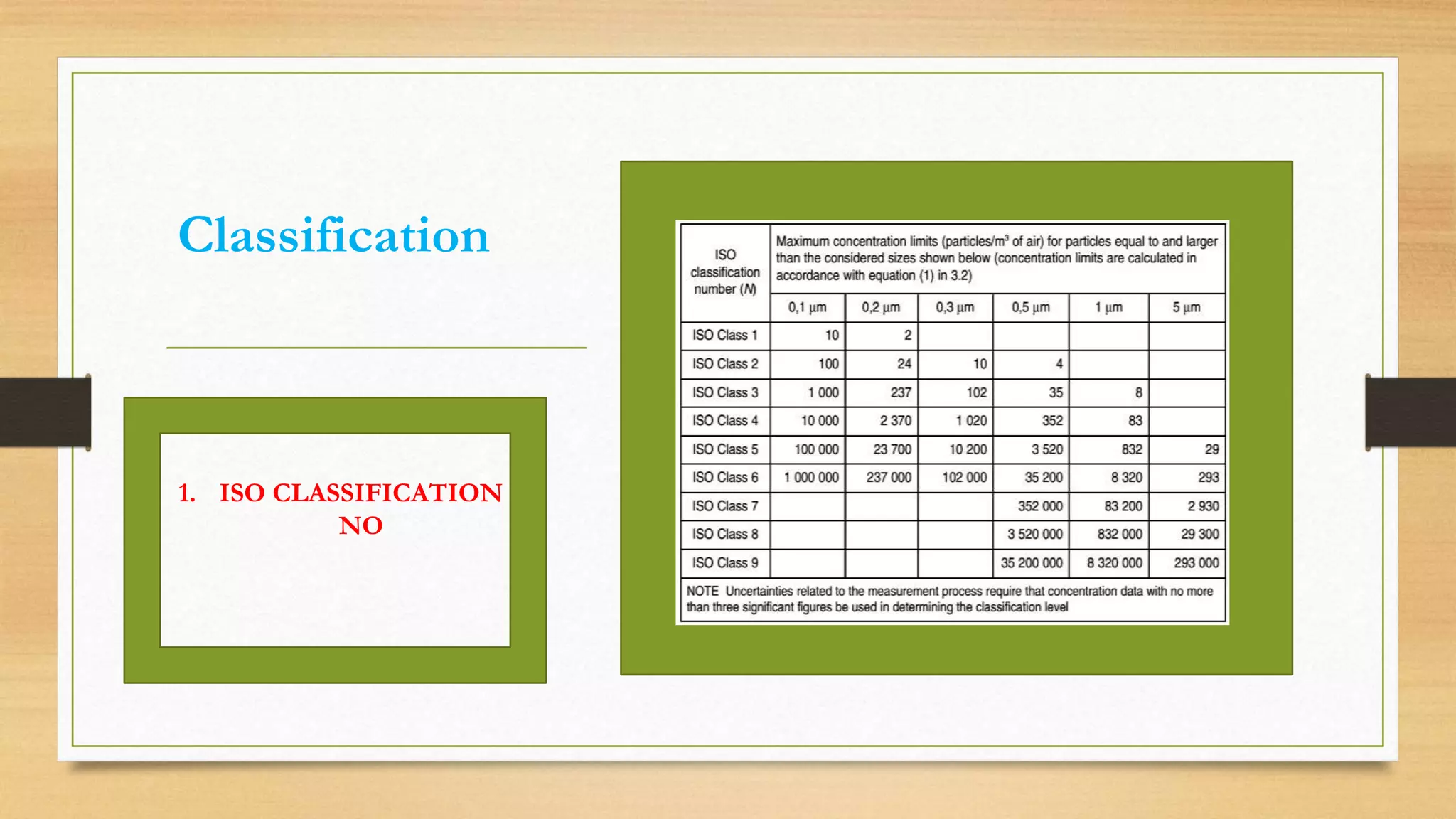
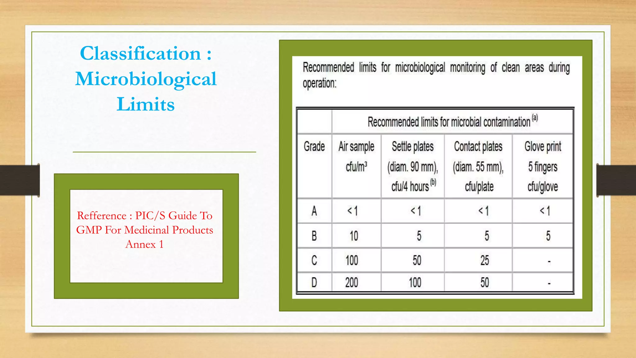
The document provides an overview of cleanroom classifications according to ISO, US Federal Standard 209E, and European standards. It discusses particle sources and control methods like filtration, dilution with higher air changes, and isolation. PIC/S guidelines recommend grade A environments with precise air control for high-risk aseptic operations, and grade B-D cleanrooms for less critical stages. Microbial limits and air monitoring frequencies are specified depending on the cleanroom grade.