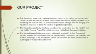
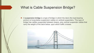
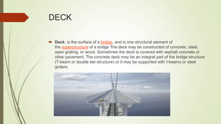
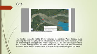
Topic: Design and Analysis of cable
suspension Bridge
MINOR
PROJECT
GROUP MEMBERS: PARTH SHUKLA -1501293
MANTU KUMAR-1501286
OUR PROJECT
 The Haldia port faces a big challenge in transportation its docked goods into the main
city as the vehicles have to run extra 10km to enter the city and deliver the goods, thus
increasing the cost and time. To overcome this situation a bridge over the Hooghly river
have been proposed to dilute the situation of goods transportation.
 The Haldia-Hooghly Bridge link have considered for construction over the Hooghly river
near Haldia Thermal Power Plant which connects Haldia Dock Complex to Kalitala.
 The Haldia-Hooghly Bridge suspension bridge with length of 3,310 m. The central
section, between the main towers may be approximately 1,600 m and the other two 855
m each. The height of the main towers can be 240 m above the water, the structure is
submerged 30 m below the water level.
Objectives:
We are going to design and analyze a cable suspension bridge taking into
consideration the basic components like deck, stiffening girder, pylon, suspender
cable, main cable , anchor and abutment and considering loads such as Live
load, dead load, wind load and seismic load. We will analyze this model in
STAAD Pro.
Also will go for Environmental impact of the Bridge. By using software like
Simapro.
We have chosen this topic as there is a uniqueness and not much work have been
done till date.
What is Cable Suspension Bridge?
 A suspension bridge is a type of bridge in which the deck (the load-bearing
portion) is hung below suspension cables on vertical suspenders. This type of
bridge has cables suspended between towers, plus vertical suspender cables that
carry the weight of the deck below, upon which traffic crosses.
Basic components
 Deck
 Stiffening Girder
 Suspension Cable
 Main Cable
 Pylon
 Abutment
 Foundation
DECK
 Deck, is the surface of a bridge, and is one structural element of
the superstructure of a bridge The deck may be constructed of concrete, steel,
open grating, or wood. Sometimes the deck is covered with asphalt concrete or
other pavement. The concrete deck may be an integral part of the bridge structure
(T-beam or double tee structure) or it may be supported with I-beams or steel
girders.
Stiffening Girder
A stiffening girder for a suspension bridge, constructed of
reinforced concrete or prestressed concrete, is formed by a
closed multi-cell box extending in the long direction of the
bridge. The upper part of the box is a substantially horizontally
extending roadway slab.
 stiffening girders have the following functions.
 They help in keeping the cables in shape
 They resist part of shear force and bending moment due to live loads.
Suspension cable
 Cables that are connected between the deck and the main cables
are called as supender cables.
These cables transfer load from stiffening girder to main cable.
They are always in tension state.
They are always perpendicular to the span.
Main Cable
 In a suspension bridge, the main cables suspend the deck (girder, roadway).
Most of the bridge's weight (and any vehicles on the bridge) is suspended from
the cables. The cables are held up only by the towers, which means that the
towers support a tremendous weight (load). The steel cables are both strong and
flexible.
Pylon
 Tower-like vertical support that usually supports the cables of a suspension bridge
or a cable-stayed bridge.
 Pylon may be casted by concrete or steel.
 Composite pylons are also preferred now a days.
 They transfer the load from the main cables to the
foundation of the bridge.
Abutment
 Abutment refers to the substructure at the ends of a bridge span or dam where
on the structure's superstructure rests or contacts
 Single-span bridges have abutments at each end which provide vertical and lateral
support for the bridge, as well as acting as retaining walls to resist lateral
movement of the earthen fill of the bridge approach. Multi-span bridges
require piers to support ends of spans unsupported by abutments.
Foundation
A caisson foundation also called as pier foundation is a watertight retaining structure
used as a bridge pier, in the construction of a concrete dam, or for the repair of ships.
It is a prefabricated hollow box or cylinder sunk into the ground to some desired depth
and then filled with concrete thus forming a foundation.
Site
The bridge connects Haldia Dock Complex to Kalitala, West Bengal, India
crossing the busy Hooghly River, which records an intense traffic maritime, with
an important port of supply and release of goods. At the time of design we have
had to think a bridge would not block sea traffic. We also took into account the
weather. It is a zone-3 Seismic area. Winds cross the river with speed 3-4 Km/h.
 Load Transfer Mechanism:
 There will be different types of loads that will act on the Bridge during its use,
 Dead Load (Self Weight of the Bridge)
 Live Load (Movement of Vehicle, Humans etc)
 Seismic Load
 Wind Load
 Load Combination
 Load from the deck will be transferred to suspended cables from which it is transferred
to main cables to the towers then to the caissons Footings. The suspended cables are
in tension due to the load of the bridge’s deck and the vehicles on it.
 X bracing is provided between the two towers which is continuously under compression
and tension due to wind and deck load. Also, angles are also provided for more
support.
 The extended part of the bridge of span 855m each, is supported on piers.
 Traffic Analysis and Bridge Data:
 According to The Hindu Business Line 4 Million Ton of goods are docked monthly.
 So, taking the maximum recorded weight of the goods in consideration, i.e
 129032.255 ton per day.
 And in India avg. weight of truck is 35 ton.
 So, no. of trucks per day= (129032.255/35) =3700 trucks.
 Divider (Provided Solar lamps) = 2m.
 Lanes: 6 (width 3.8m each).
 Toll plaza (At the far ends).
 Cantilever footpath 3m either side (due to up thrust Wind effect)
 Ratio of span to width= 1600/40 = 40m.
 Therefore, total width = 40m (20 to 56 considered).
 5m High Tide Level
 Total Height: 225m = 225m
 Total tower height= 160m
 Depth of stiffening Truss: 5m
 Sag: 1600*0.1 = 160m

Presentation on Suspension Bridge

  • 1.
    Topic: Design andAnalysis of cable suspension Bridge MINOR PROJECT GROUP MEMBERS: PARTH SHUKLA -1501293 MANTU KUMAR-1501286
  • 2.
    OUR PROJECT  TheHaldia port faces a big challenge in transportation its docked goods into the main city as the vehicles have to run extra 10km to enter the city and deliver the goods, thus increasing the cost and time. To overcome this situation a bridge over the Hooghly river have been proposed to dilute the situation of goods transportation.  The Haldia-Hooghly Bridge link have considered for construction over the Hooghly river near Haldia Thermal Power Plant which connects Haldia Dock Complex to Kalitala.  The Haldia-Hooghly Bridge suspension bridge with length of 3,310 m. The central section, between the main towers may be approximately 1,600 m and the other two 855 m each. The height of the main towers can be 240 m above the water, the structure is submerged 30 m below the water level.
  • 3.
    Objectives: We are goingto design and analyze a cable suspension bridge taking into consideration the basic components like deck, stiffening girder, pylon, suspender cable, main cable , anchor and abutment and considering loads such as Live load, dead load, wind load and seismic load. We will analyze this model in STAAD Pro. Also will go for Environmental impact of the Bridge. By using software like Simapro. We have chosen this topic as there is a uniqueness and not much work have been done till date.
  • 4.
    What is CableSuspension Bridge?  A suspension bridge is a type of bridge in which the deck (the load-bearing portion) is hung below suspension cables on vertical suspenders. This type of bridge has cables suspended between towers, plus vertical suspender cables that carry the weight of the deck below, upon which traffic crosses.
  • 5.
    Basic components  Deck Stiffening Girder  Suspension Cable  Main Cable  Pylon  Abutment  Foundation
  • 6.
    DECK  Deck, isthe surface of a bridge, and is one structural element of the superstructure of a bridge The deck may be constructed of concrete, steel, open grating, or wood. Sometimes the deck is covered with asphalt concrete or other pavement. The concrete deck may be an integral part of the bridge structure (T-beam or double tee structure) or it may be supported with I-beams or steel girders.
  • 7.
    Stiffening Girder A stiffeninggirder for a suspension bridge, constructed of reinforced concrete or prestressed concrete, is formed by a closed multi-cell box extending in the long direction of the bridge. The upper part of the box is a substantially horizontally extending roadway slab.  stiffening girders have the following functions.  They help in keeping the cables in shape  They resist part of shear force and bending moment due to live loads.
  • 8.
    Suspension cable  Cablesthat are connected between the deck and the main cables are called as supender cables. These cables transfer load from stiffening girder to main cable. They are always in tension state. They are always perpendicular to the span.
  • 9.
    Main Cable  Ina suspension bridge, the main cables suspend the deck (girder, roadway). Most of the bridge's weight (and any vehicles on the bridge) is suspended from the cables. The cables are held up only by the towers, which means that the towers support a tremendous weight (load). The steel cables are both strong and flexible.
  • 10.
    Pylon  Tower-like verticalsupport that usually supports the cables of a suspension bridge or a cable-stayed bridge.  Pylon may be casted by concrete or steel.  Composite pylons are also preferred now a days.  They transfer the load from the main cables to the foundation of the bridge.
  • 11.
    Abutment  Abutment refersto the substructure at the ends of a bridge span or dam where on the structure's superstructure rests or contacts  Single-span bridges have abutments at each end which provide vertical and lateral support for the bridge, as well as acting as retaining walls to resist lateral movement of the earthen fill of the bridge approach. Multi-span bridges require piers to support ends of spans unsupported by abutments.
  • 12.
    Foundation A caisson foundationalso called as pier foundation is a watertight retaining structure used as a bridge pier, in the construction of a concrete dam, or for the repair of ships. It is a prefabricated hollow box or cylinder sunk into the ground to some desired depth and then filled with concrete thus forming a foundation.
  • 13.
    Site The bridge connectsHaldia Dock Complex to Kalitala, West Bengal, India crossing the busy Hooghly River, which records an intense traffic maritime, with an important port of supply and release of goods. At the time of design we have had to think a bridge would not block sea traffic. We also took into account the weather. It is a zone-3 Seismic area. Winds cross the river with speed 3-4 Km/h.
  • 14.
     Load TransferMechanism:  There will be different types of loads that will act on the Bridge during its use,  Dead Load (Self Weight of the Bridge)  Live Load (Movement of Vehicle, Humans etc)  Seismic Load  Wind Load  Load Combination  Load from the deck will be transferred to suspended cables from which it is transferred to main cables to the towers then to the caissons Footings. The suspended cables are in tension due to the load of the bridge’s deck and the vehicles on it.  X bracing is provided between the two towers which is continuously under compression and tension due to wind and deck load. Also, angles are also provided for more support.  The extended part of the bridge of span 855m each, is supported on piers.
  • 15.
     Traffic Analysisand Bridge Data:  According to The Hindu Business Line 4 Million Ton of goods are docked monthly.  So, taking the maximum recorded weight of the goods in consideration, i.e  129032.255 ton per day.  And in India avg. weight of truck is 35 ton.  So, no. of trucks per day= (129032.255/35) =3700 trucks.  Divider (Provided Solar lamps) = 2m.  Lanes: 6 (width 3.8m each).  Toll plaza (At the far ends).  Cantilever footpath 3m either side (due to up thrust Wind effect)  Ratio of span to width= 1600/40 = 40m.  Therefore, total width = 40m (20 to 56 considered).  5m High Tide Level  Total Height: 225m = 225m  Total tower height= 160m  Depth of stiffening Truss: 5m  Sag: 1600*0.1 = 160m