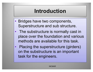
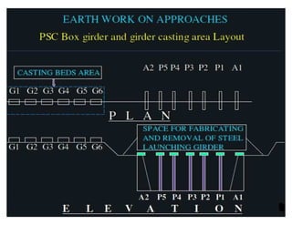
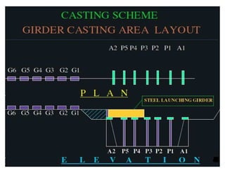
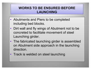
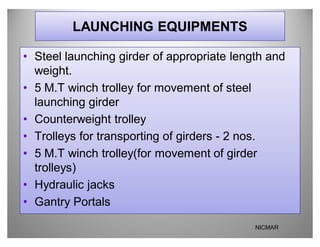
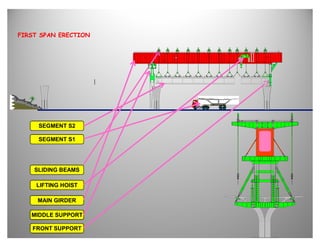
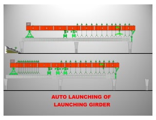
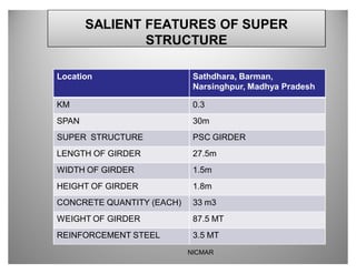
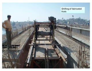
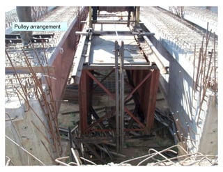
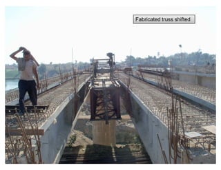
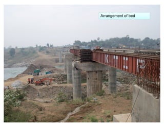
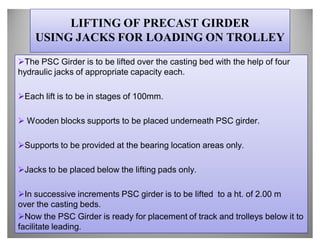
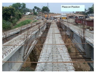
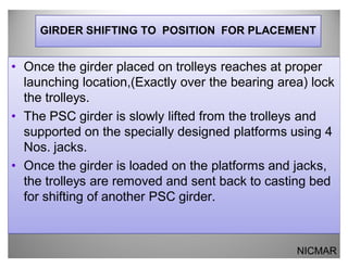
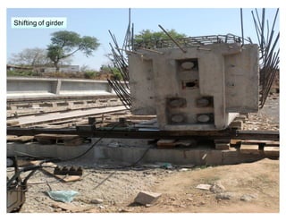
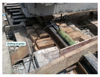
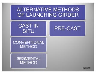
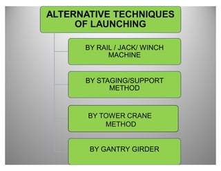
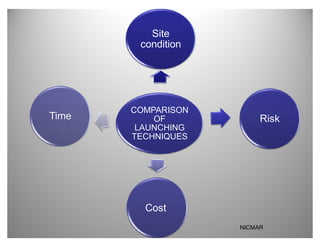
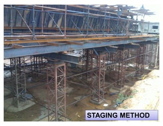
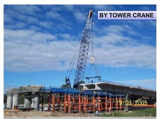
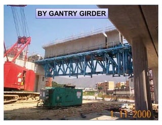
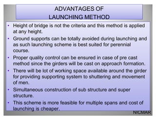
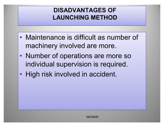
This document provides information about launching girders for bridge construction. It discusses the necessary preparations before launching including completing abutments and piers. It describes the launching equipment used such as the steel launching girder, winches, and trolleys. The document outlines the process for shifting the launching girder and launching precast concrete girders segment by segment onto the bridge. It compares different launching techniques and discusses advantages such as allowing construction at any height and simultaneous work on substructure and superstructure.
Girder Bridge is most critical construction technique with all aspects. For fast tracking this kind of projects new and efficient machines are used. Some details given to this presentation for better understanding and knowledge.
Permanent Way of Railway & Components ?(part -1,2,3,4,5)RAMPRASAD KUMAWAT
Permanent Way Components: , Selection of Alignment, Ideal Permanent Ways and Cross-sections in different conditions, Salient Features and types of Components viz.
Rails, Sleepers, Ballast, Rail Fastenings.
Types and Selection of Gauges
Design of steel structure as per is 800(2007)ahsanrabbani
It does not offer resistance against rotation and also termed as a hinged or pinned connections.
It transfers only axial or shear forces and it is not designed for moment
It is generally connected by single bolt/rivet and therefore full rotation is allowed
Geometric Design of Railways in India is explained. Design of horizontal curves, speed on curves, super-elevation, cant deficiency, transition curves etc. are included
Bridge Bearings has been considered as of huge importance in civil engineering. It plays a significant role in the structure of bridges. This presentation covers the complete study of Bridge Bearings.
this presentation describes in details the sinking operation of well foundations in different conditions and situations. the content here is suitable only for basic knowledge and educational purposes.
The PiBox Launcher was designed to be a replaceable component within the PiBox Media Center, similar to but much simpler than the launchers on Android. This talk describes the design and implementation of the launcher application.
Comparative study on normal and skew bridge of psc box girdereSAT Journals
Abstract Nowadays the demand for high skew bridges has increased, and many bridge decks are built with some form of skew. The behavior of bridge is effected considerably with the presence of skew angle in bridge decks. In the present study an attempt has been made to study the skew bridge comparing with the normal bridge for skew angle 10, 20, 30, 40, 50. The finite element analysis is carried out for single span, two span and three span deck for dead load and moving load (IRC class 70R) loading using software SAP2000 ver.14. The results are presented in terms of displacement, bending moment and shear force. Keywords: Skew bridges, skew angle, PSC box girder, span length
Civil 2014 (v2.1) is released now. The following features have been newly implemented.
Improvements in Eurocode Moving Load Analysis
- Centrifugal Forces
- Eccentricity of Vertical Loads of Rail Traffics
- Concurrent Stresses
- User-defined Railway Traffic Loads
- User-defined Permit Truck Loads
- Concurrent Reactions
Simultaneous Display of Top and Bottom Stress Diagram in Bridge Girder Diagram
Auto-calculation of Effective Slab Width as per Eurocode
Update Geometry of Analysis Model using Buckling Mode Shape
Easy and Fast Generation of Strands/Tendons
For details, please refer to the attached Civil 2014 (v2.1) Release Note.
SSRC Presentation of Telmo Andres SanchezEva Lantsoght
The incremental launching method (ILM) is commonly used for bridges where erection procedures cannot be conducted from below the superstructure. In this method, the steel components are assembled on one side of the obstacle and moved longitudinally to the other supports. Deep valleys with steep slopes and environmentally sensitive areas are examples where the use of the ILM is justified. During the launching operation, the bridge I-girders cantilever out from their initial position and may be prone to stability related problems such as global lateral-torsional buckling of the system, as well as high strength demands at the cantilever support. This paper presents studies of the behavior of a three-span steel I-girder bridge consisting of four parallel girders erected with the ILM. Critical construction stages are investigated to determine the structural responses according to the AASHTO LRFD Bridge Design Specifications. These results are compared to the responses obtained from refined three-dimensional finite element models (FEM) to verify the applicability of current design methodologies for bridges erected with the ILM. In particular, analyses are conducted to assess the validity of the construction checks in the AASHTO Specifications of girders in cantilever and of systems potentially subjected to global lateral-torsional buckling. Based on the results of the studies, recommendations are provided to conduct a stability assessment of bridges erected by applying this method.
(Note: this is not my work, but the work of M.E. Ponton, A. Robalino and T.A. Sanchez - I'm just hosting this on my profile)
A presentation of a precast segmental casting yard setup showing the required sequential steps. At the time, I worked for Parsons Brinckerhoff as Lead Construction Engineer.
Redesigning Input-Method Launcher and Management SystemFuminobu Takeyama
Input methods allow us to input characters that cannot be written directly by keyboard. They are essential feature for people who use languages such as Chinese, Korean, and Japanese. openSUSE provides several input methods and such users can access to an input method relatively easily.
However, openSUSE’s mechanism to launch and manage input methods is more than ten years old; now, it shows several limitations. For example, input methods do not follow DPI settings from the current desktop environment. Furthermore, there is no good GUI for switching to their favorite input method. It is also difficult to enable input methods under English environment.
In this talk, I will propose a new input-method launcher and management system. The launcher part is called chameleon tongue. It supports modern desktop environments such as Plasma 5 and provides interfaces friendly with frontend applications. Then, we will discuss design of the new management frontend.
Engineering-Design-Manufacturing-Assembly of all kind of equipments and services from a single spare parts to complete LF or complete meltshop. Ladles, ladle cars, gas purging stations, emergency lance stirrers, wire feeders, material handling systems, Slab Turnover Device, etc. Training and advisory services. Complete turnkey projects for Mini Steel Plant and rolling mills.
selection operation and maintainance of mobile cranes ( for education purpose...swaroop k s
A mobile cranes are machine that could lift, pull, tug, carry, and do many such things that are done on a large scale. It is a cable-controlled crane mounted on crawlers or rubber-tired carriers or a hydraulic-powered crane with a telescoping boom mounted on truck- type carriers or as self-propelled models. They are commonly used in the construction industry and in the manufacturing of heavy equipment.
Rough Terrain Crane A crane that is mounted on an undercarriage with four rubber tires, designed for operations off road. The outriggers extend vertically and horizontally to level and stabilize the crane when hoisting. These types of cranes are single engine machines where the same engine is used for powering the undercarriage as it is for powering the crane. In these types of cranes, the engine is normally mounted in the undercarriage rather than in the upper portion.
These cranes can go from the paved highway to the rocky landscape of a job site. They can reach speeds necessary to travel on public highways, yet have the power necessary to handle a variety of construction tasks. This mainstay of the heavy equipment industry main asset is its versatility. All terrain cranes can handle up to 1,300 short tons of weight
Telescopic handler cranes are essentially forklift trucks with a telescoping boom attached to them. These cranes can be driven in 360 degrees and are often used for tasks like moving pallets of bricks or hoisting framing trusses in place.
Constant updating of load spectra, evolution of standards, regulations, rules and calculation methods has increased the importance of seismic evaluation of NPP structures.
Few rules to be followed like:
•Equipments are classified as Class I, Class II and Class-III.
•ASME Section III Div 1 subsection NB, NC, ND based on the seismic safety class of the equipment.
•Supports qualified as per ASME section III Div 1 subsection NF.
We supply overhead crane,gantry crane,jib crane,crane parts,port crane,electric hoist! Our cost performance is high,the quotation and the transportation way,belive that will make you satisfied. Welcom to inquiry!
skype:
cherry.swallow
Email:
christine@ytcrane.com
Web:
http://www.ytcrane.com
Cam and follower theory prof. sagar a dhotareSagar Dhotare
This ppt covers following points,
Classification of Cam and Follower
Terminology of cam
Importance of Pressure angle
Application of Cam and Follower
Importance of cam and follower
Presentation on railway construction and maintenance
62617938 launching-girder
1. Presentation
On
LAUNCHING GIRDER
Guided by: Submitted By
Prof. A. GOSAVI Rohan Kaple (G04117)
Hiren Patel (G04130)
Kundan Rathod (G04138)
National Institute Of Construction Management & Research Goa Campus
2. Introduction
‡ Bridges have two components,
Superstructure and sub structure.
‡ The substructure is normally cast in
place over the foundation and various
methods are available for this task.
‡ Placing the superstructure (girders)
on the substructure is an important
task for the engineers.
NICMAR
6. WORKS TO BE ENSURED BEFORE
LAUNCHING
‡ Abutments and Piers to be completed
including bed blocks.
‡ Dirt wall and fly wings of Abutment not to be
concreted to facilitate movement of steel
Launching girder.
‡ The fabricated launching girder is assembled
on Abutment side approach in the launching
direction.
‡ Track is welded on steel launching
7. LAUNCHING EQUIPMENTS
‡ Steel launching girder of appropriate length and
weight.
‡ 5 M.T winch trolley for movement of steel
launching girder
‡ Counterweight trolley
‡ Trolleys for transporting of girders - 2 nos.
‡ 5 M.T winch trolley(for movement of girder
trolleys)
‡ Hydraulic jacks
‡ Gantry Portals
NICMAR
8. FIRST SPAN ERECTION
SEGMENT S2
SEGMENT S1
SLIDING BEAMS
LIFTING HOIST
MAIN GIRDER
MIDDLE SUPPORT
FRONT SUPPORT
9. NORMAL SPAN ERECTION
SEGMENT S2
SEGMENT S1
SLIDING BEAMS
LIFTING HOIST
MAIN GIRDER
REAR TROLLEY
REAR SUPPORT
MIDDLE SUPPORT
FRONT SUPPORT
12. SALIENT FEATURES OF SUPER
STRUCTURE
Location Sathdhara, Barman,
Narsinghpur, Madhya Pradesh
KM 0.3
SPAN 30m
SUPER STRUCTURE PSC GIRDER
LENGTH OF GIRDER 27.5m
WIDTH OF GIRDER 1.5m
HEIGHT OF GIRDER 1.8m
CONCRETE QUANTITY (EACH) 33 m3
WEIGHT OF GIRDER 87.5 MT
REINFORCEMENT STEEL 3.5 MT
NICMAR
13. SHIFTING OF LAUNCHING GIRDER
PROJECT DESCRIPTION
‡ The steel girder is pulled with the help of power
operated winch and is placed on first two spans i.e. on
abutment and adjacent pier.
‡ Rollers are placed on bank and on the bed blocks for
shifting.
‡ After proper position of launching girder, remove the
rollers and ensure firm sitting of launching girder on the
bed blocks.
‡ Construct dirt wall , fly wings of ABUTMENT .
‡ Now the launching girder is ready for launching of PSC
girder.
NICMAR
19. LIFTING OF PRECAST GIRDER
USING JACKS FOR LOADING ON TROLLEY
The PSC Girder is to be lifted over the casting bed with the help of four
hydraulic jacks of appropriate capacity each.
Each lift is to be in stages of 100mm.
Wooden blocks supports to be placed underneath PSC girder.
Supports to be provided at the bearing location areas only.
Jacks to be placed below the lifting pads only.
In successive increments PSC girder is to be lifted to a ht. of 2.00 m
over the casting beds.
Now the PSC Girder is ready for placement of track and trolleys below it to
facilitate leading.
23. GIRDER PLACED ON TROLLEY AND SHIFTING
TO THE SPAN
‡ Keep the PSC girder over the hydraulic jacks placed
below the lifting heads.
‡ Remove the wooden blocks in the bearing area for
linking purpose.
‡ Link the track below the PSC girder.
‡ Place two trolleys below the PSC girder in the
bearing area.
‡ Rest the PSC girder over the trolley by lowering
hydraulic jacks.
‡ Remove the wooden blocks and hydraulic jacks.
‡ Now the trolleys are ready to shift to the first span.
‡ Shift the PSC girder using winch machine.
26. GIRDER SHIFTING TO POSITION FOR PLACEMENT
‡ Once the girder placed on trolleys reaches at proper
launching location,(Exactly over the bearing area) lock
the trolleys.
‡ The PSC girder is slowly lifted from the trolleys and
supported on the specially designed platforms using 4
Nos. jacks.
‡ Once the girder is loaded on the platforms and jacks,
the trolleys are removed and sent back to casting bed
for shifting of another PSC girder.
NICMAR
35. ADVANTAGES OF
LAUNCHING METHOD
‡ Height of bridge is not the criteria and this method is applied
at any height.
‡ Ground supports can be totally avoided during launching and
as such launching scheme is best suited for perennial
course.
‡ Proper quality control can be ensured in case of pre cast
method since the girders will be cast on approach formation.
‡ There will be lot of working space available around the girder
for providing supporting system to shuttering and movement
of men.
‡ Simultaneous construction of sub structure and super
structure.
‡ This scheme is more feasible for multiple spans and cost of
launching is cheaper.
NICMAR
36. DISADVANTAGES OF
LAUNCHING METHOD
‡ Maintenance is difficult as number of
machinery involved are more.
‡ Number of operations are more so
individual supervision is required.
‡ High risk involved in accident.
NICMAR