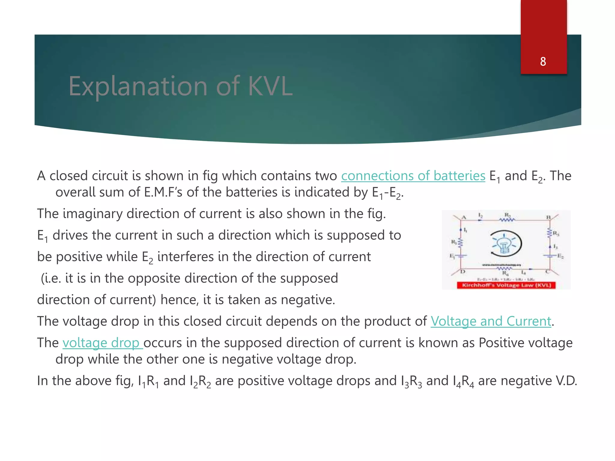
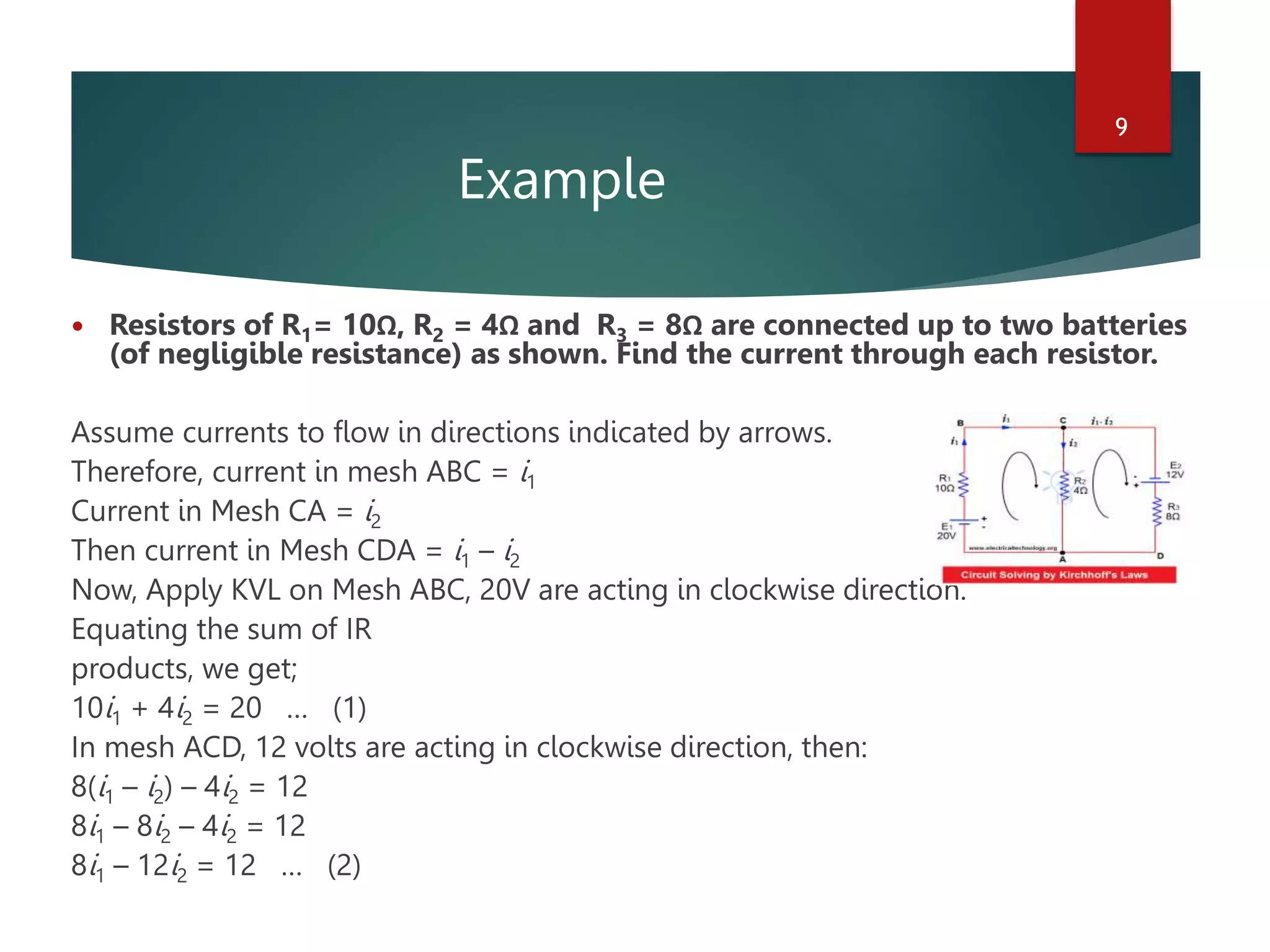
This is a ppt of a college project of the topic kvl and kcl ..do read this..i have such interest in science projects and do maake aa lot of money by doing freelancing in embedded system so make sure to check this ppt for more updtes
ECG Graph Monitoring with AD8232 ECG Sensor & Arduino.pptx
KVL & KCL
1. KVL &
KCL
NAME- SAIKAT BISWAS
UNIVERSITY ROLL NO- 14200321028
MEGHNAD SAHA INSTITUTE OF TECHNOLOGY
1
2. 2
Terminology: Nodes and Branches
Node: A point where two or more circuit elements
are connected
Branch: A path that connects two nodes
3. 3
Kirchhoff’s Laws
• Kirchhoff’s Current Law (KCL):
– The algebraic sum of all the currents entering any node in a
circuit equals zero. (An expression of the conservation of
charge.)
• Kirchhoff’s Voltage Law (KVL):
– The algebraic sum of all the voltages around any loop in a
circuit equals zero. (As a result of conservation of energy.)
4. 4
Alternative Formulations of Kirchhoff’s Current
Law
(Charge stored in node is zero.)
Formulation 1:
Sum of currents entering node
= sum of currents leaving node
Formulation 2:
Algebraic sum of currents entering node = 0
• Currents leaving are included with a minus sign.
Formulation 3:
Algebraic sum of currents leaving node = 0
• Currents entering are included with a minus sign.
5. Explanation of KCL:
Suppose some conductors are meeting at a point “A” as shown in fig 1.a. In
some conductors, currents are incoming to the point “A” while in other
conductors, Currents are leaving or outgoing from point “A”.
Consider the incoming or entering currents as “Positive (+) towards point “A”
while the leaving or outgoing currents from point “A” is “Negative (-)”.
then:
I1 + (–I2) + (–I3) + (–I4) + I5 = 0
OR
I1 + I5 – I2 – I3 – I4 = 0 OR
I1 + I5 = I2 + I3 + I4 = 0
i.e.
Incoming or Entering Currents = Leaving or Outgoing Currents
Or
ΣI Entering = ΣI Leaving
5
6. Kirchhoff’s Current Law, KCL
6
KCL at node 2:
I I
I I I
V V V V V V
entering leaving
R R R
1 3 2
1 2 0 2 2 3
2 2 1 3
. k .0 k .7 k
Shade indicates a node
At node 1, V1=3 v. due to source
At node 0, V0=0 v. due to ground
KCL at node 3:
V V V V
2 3 3 0
3 7
. k 5.4 k
3 V
R1
2.2 k
R2
3.7 k
R4
5.4 k
R3
1.0 k
1 2 3
0
IR1
IR2
IR3
IR2
IR4
7. 7
Formulations of Kirchhoff’s Voltage Law
(Conservation of energy)
Formulation 1:
Sum of voltage drops around loop
= sum of voltage rises around loop
Formulation 2:
Algebraic sum of voltage drops around loop = 0
• Voltage rises are included with a minus sign.
Formulation 3:
Algebraic sum of voltage rises around loop = 0
• Voltage drops are included with a minus sign.
8. Explanation of KVL
A closed circuit is shown in fig which contains two connections of batteries E1 and E2. The
overall sum of E.M.F’s of the batteries is indicated by E1-E2.
The imaginary direction of current is also shown in the fig.
E1 drives the current in such a direction which is supposed to
be positive while E2 interferes in the direction of current
(i.e. it is in the opposite direction of the supposed
direction of current) hence, it is taken as negative.
The voltage drop in this closed circuit depends on the product of Voltage and Current.
The voltage drop occurs in the supposed direction of current is known as Positive voltage
drop while the other one is negative voltage drop.
In the above fig, I1R1 and I2R2 are positive voltage drops and I3R3 and I4R4 are negative V.D.
8
9. Example
Resistors of R1= 10Ω, R2 = 4Ω and R3 = 8Ω are connected up to two batteries
(of negligible resistance) as shown. Find the current through each resistor.
Assume currents to flow in directions indicated by arrows.
Therefore, current in mesh ABC = i1
Current in Mesh CA = i2
Then current in Mesh CDA = i1 – i2
Now, Apply KVL on Mesh ABC, 20V are acting in clockwise direction.
Equating the sum of IR
products, we get;
10i1 + 4i2 = 20 … (1)
In mesh ACD, 12 volts are acting in clockwise direction, then:
8(i1 – i2) – 4i2 = 12
8i1 – 8i2 – 4i2 = 12
8i1 – 12i2 = 12 … (2)
9
10. Multiplying equation (1) by 3;
30i1 + 12i2 = 60
Solving for i1
30i1 + 12i2 = 60
8i1 – 12i2 = 12
___________
38i1 = 72
i1 = 72 ÷ 38 = 1.895 Amperes = Current in 10 Ohms resistor
Substituting this value in (1), we get:
10 (1.895) + 4i2 = 20
4i2 = 20 – 18.95
i2 = 0.263 Amperes = Current in 4 Ohms Resistors.
Now,
i1 – i2= 1.895 – 0.263 = 1.632 Amperes
10
11. Applications of Kirchhoff’s Laws
Kirchhoff’s laws can be used to determine the values of unknown values
like current and Voltage as well as the direction of the flowing values of these
quintets in the circuit.
These laws can be applied on any circuit* (See the limitation of Kirchhoff’s
Laws at the end of the article), but useful to find the unknown values in
complex circuits and networks.
Also used in Nodal and Mesh analysis to find the values of current and
voltage.
Current through each independent loop is carried by applying KVL (each loop)
and current in any element of a circuit by counting all the current (Applicable
in Loop Current Method).
Current through each branch is carried by applying KCL (each junction) KVL in
each loop of a circuit (Applicable in Loop Current Method).
Kirchhoff’s Laws are useful in understanding the transfer of energy through an
electric circuit.
11