MESH NODAL DC.pptx
•Download as PPTX, PDF•
0 likes•39 views

Mesh and Nodal analysis introduction

Recommended
More Related Content
What's hot
What's hot (20)
Similar to MESH NODAL DC.pptx
Similar to MESH NODAL DC.pptx (20)
Recently uploaded
Recently uploaded (20)
MESH NODAL DC.pptx
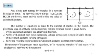
- 1. Any closed path formed by branches in a network is called as mesh. The network shown in Fig(1) ABDA and BCDB are the two mesh and we need to find the value of each mesh current. The number of equations is equal to the number of meshes in the circuit. The procedure used in applying the mesh current method to linear circuit is given below 1. Define each mesh currents in a clockwise direction. 2. Apply KVL around each mesh expressing voltage across each element in terms of one or more mesh currents flowing through it. 3. Solve the resulting linear equations with mesh currents as dependent variables. MESH: 1 D Fig 1 2 V 1 R 1 V 1 I 2 I A C B 2 R 3 R The number of independent mesh equations, ‘m’ is related to branches ‘b’ and nodes ‘n’ in an electrical network by the equation m=b-n+1
- 2. Steps to solve the mesh current method By applying KVL to the network shown in fig(1), we get the equations, For mesh ABDA Mesh Current Method: 1 1 1 2 2 1 1 1 2 2 2 1 -I R -(I -I )R +V =0 I (R +R ) I R =V 1 2 2 V 1 R 1 V 1 I 2 I A C B D Fig 1 2 R 3 R 1 2 (I -I ) 1 I 2 I For mesh BCDB 2 3 2 2 1 2 1 2 2 2 3 2 -I R -V -(I -I )R =0 I R I (R +R )=V 2 The mesh currents are find out by solving the equations (1) and (2)
- 3. Example problem: 3 30 1 V 120V 1 I 2 I A C B D Fig 2 50 10 1 2 (I -I ) 1 I 2 I 2 V 60V 1 2 1 1 2 -30I -10(I -I )+120=0 40I 10I 120 1 1.Find the mesh current for the network shown in fig (2) Solution: First assign mesh currents to the meshes ABDA and BCDB For Mesh ABDA For Mesh BCDB 2 2 1 1 2 -50I -60-10(I -I )=0 -10I 60I 60 2 By solving equation (1) and (2) we get the two mesh currents
- 4. Multiplying equation (2) by 4 and adding it to equation (1), we get 1 2 I 0.521 I = 2.86A 4 1 2 1 2 2 40I 10I 120 1 4*(2) ( ) -40I 240I 240 3 I 0.521A (4) Substitute equation (4) in the equation (1) and we can find the value of 2 I 1 2 1 1 1 1 40I 10( 0.521) 120 I =-0.521A (1) 40I 120 5.21 120 5.21 I 40 I 2.86A 5 The mesh currents in the network given is Similarly we can solve more number of meshes with same set of procedures.
- 5. Super Mesh: 5 In an electrical circuit if there is any common independent current source for two meshes, then it is difficult to write and analysis the mesh current method. In such a case, it is difficult to assign a voltage to the independent current sources since a current source will supply rated current at all voltages. In order to solve such a electrical network we introduce the concept of ‘super mesh’. If there is two current sources in a circuit then by source conversion techniques we can convert one current source into voltage source(adding resistance in series) and apply the super mesh technique. Fig 3 2 d b 10 3 I 5 3 V 50 1 1 I 2 I 2A f c e a In fig (3) the current source is common to mesh ‘befcb’ and mesh ‘cfdc’, so now we can form the super mesh for this network. For the circuit shown in fig (3) fid the current in the 5Ω resistor by using super mesh.
- 6. 6 1 2 2 1 3 1 2 3 10(I -I )+2I +5(I -I ) =50 15I 10I 5I 50 1 Solution: Apply KVL for the mesh ‘abcda’ we get 2 d b 10 3 I 5 3 V 50 1 1 I 2 I 2A f c e a From the second(befcb) and third(cfdc) meshes, we can form a super mesh 2 1 2 3 3 1 1 2 3 10(I -I )+2I +I +5(I -I ) =0 -15I 12I +6I 0 2 The current source is equal to the difference between Second and third mesh currents, that is given by 2 3 I -I =2A 3 Solving equation (1), (2) and (3) we have 1 2 3 I =19.99A 4 I =17.33A 5 I =15.33A 6 The current in the 5Ω resistor is 1 3 I -I =4.66A 7
- 7. Nodal analysis: 7 A node is defined as a junction of three or more branches. The nodal method is used to analyze multisource(current source) circuits. Kirchhoff’s current law is used to develop the method referred to as nodal analysis. Steps in nodal analysis • Determine the number of nodes within the network. • Pick a reference node, and label each remaining node with a subscript value of voltage: V1, V2, and so on. • Apply Kirchhoff’s current law at each node except the reference node. • Solve the resulting equation to get the voltages at each node. 1 I 2 I 1 R 2 R 3 R 4 R 5 R 1 V 2 V 3 V (1) (2) (3)
- 8. 8 Steps in nodal analysis (super node) In some occasion there will be independent voltage sources in the network to which nodal analysis is to be applied. If so, convert the voltage source to a current source if a series resistor is present, If not use the supernode approach. • Assign a nodal voltage to each independent node of the network. • Replace independent voltage sources with short-circuits. • Apply KCL to the defined nodes of the network. • Relate the defined nodes to the independent voltage source of the network, and solve for the nodal voltages.
- 9. 9 1 I 2 I 1 R 2 R 3 R 1 V 2 V (1) (2) (3) node Ref. 1 I 2 I R3 I R1 I R2 I Consider the above circuit shown, in this circuits there are three nodes so it is possible to write 2 (n-1) equations. Nodal analysis: Formation
- 10. 10 Applying KCL at node 1 gives R3 R1 1 I I I 0 I I I R3 R1 1 Where 3 2 1 R3 1 1 R1 R V V I R V I Hence 0 R V V R V I 3 2 1 1 1 1 Applying KCL at node 2 gives R3 R2 2 I I I 0 I I I R2 R3 2 Where 3 2 1 R3 2 2 R2 R V V I R V I Hence 0 R V R V V I 2 2 3 2 1 2 (1) (2) By rearranging and solving equation 1 and 2, nodal voltages V1 and V2 are obtained.
- 11. 11 Using nodal analysis, determine the current flowing through 20Ω resistor 1A 2A 20 1 V 2 V (1) (2) (3) node Ref. 1 I 2 I R3 I R1 I R2 I 5 10 Nodal analysis: Example
- 12. 12 Applying KCL at node 1 gives R3 R1 1 I I I Where 10 V V I 20 V I 2 1 R3 1 R1 Hence 10 V V 20 V 1 2 1 1 Applying KCL at node 2 gives R3 R2 I I 2 Where 10 V V I 5 V I 2 1 R3 2 R2 Hence 5 V 10 V V 2 2 2 1 (1) (2) By rearranging and solving equation 1 and 2, nodal voltages V1 and V2 are obtained. Solution
- 13. 13 2 1 2 1 2 1 1 2 1 1 V 2 3V 20 20 V 2 3V 1 20 V 2 20 2V 20 V 1 10 V 10 V 20 V 1 1 equation (3) Solution 2 1 2 1 2 2 1 2 2 1 V 3 V 20 10 V 3 V 2 10 2V 10 V 10 V 2 5 V 10 V V 2 2 equation (4) Solving (3) and (4) you get 5.714V V 2.858V V 2 1 Current flowing through 20Ω resistor 0.1429A 20 2.858 20 V I 1 R1