Mesh analysis is a circuit analysis technique that uses mesh currents as variables. It involves identifying loops called meshes, applying Kirchoff's voltage law (KVL) to each mesh to write equations relating the mesh currents, and solving the equations simultaneously. Mesh analysis is best for circuits with fewer meshes than nodes and works for planar circuits. Nodal analysis uses node voltages as variables and is better for circuits with fewer nodes than meshes, as well as non-planar circuits and circuits with current sources. Both techniques have their uses, and it is good to be familiar with both.
An Approach for Power Flow Analysis of Radial Distribution Networksresearchinventy
This paper provides an easy and effective approach to the load flow solution of Radial distribution networks. As compared to the various methods proposed in the past, this work presents a new technique consisting of load flow solution of the network, facilitated by the identification of all the nodes beyond a particular branch. The proposed method is quite accurate and reliable for the system having any number of nodes. The primary target of this work is to evaluate the results with high precision and convergence.
Search and Society: Reimagining Information Access for Radical FuturesBhaskar Mitra
The field of Information retrieval (IR) is currently undergoing a transformative shift, at least partly due to the emerging applications of generative AI to information access. In this talk, we will deliberate on the sociotechnical implications of generative AI for information access. We will argue that there is both a critical necessity and an exciting opportunity for the IR community to re-center our research agendas on societal needs while dismantling the artificial separation between the work on fairness, accountability, transparency, and ethics in IR and the rest of IR research. Instead of adopting a reactionary strategy of trying to mitigate potential social harms from emerging technologies, the community should aim to proactively set the research agenda for the kinds of systems we should build inspired by diverse explicitly stated sociotechnical imaginaries. The sociotechnical imaginaries that underpin the design and development of information access technologies needs to be explicitly articulated, and we need to develop theories of change in context of these diverse perspectives. Our guiding future imaginaries must be informed by other academic fields, such as democratic theory and critical theory, and should be co-developed with social science scholars, legal scholars, civil rights and social justice activists, and artists, among others.
State of ICS and IoT Cyber Threat Landscape Report 2024 previewPrayukth K V
The IoT and OT threat landscape report has been prepared by the Threat Research Team at Sectrio using data from Sectrio, cyber threat intelligence farming facilities spread across over 85 cities around the world. In addition, Sectrio also runs AI-based advanced threat and payload engagement facilities that serve as sinks to attract and engage sophisticated threat actors, and newer malware including new variants and latent threats that are at an earlier stage of development.
The latest edition of the OT/ICS and IoT security Threat Landscape Report 2024 also covers:
State of global ICS asset and network exposure
Sectoral targets and attacks as well as the cost of ransom
Global APT activity, AI usage, actor and tactic profiles, and implications
Rise in volumes of AI-powered cyberattacks
Major cyber events in 2024
Malware and malicious payload trends
Cyberattack types and targets
Vulnerability exploit attempts on CVEs
Attacks on counties – USA
Expansion of bot farms – how, where, and why
In-depth analysis of the cyber threat landscape across North America, South America, Europe, APAC, and the Middle East
Why are attacks on smart factories rising?
Cyber risk predictions
Axis of attacks – Europe
Systemic attacks in the Middle East
Download the full report from here:
https://sectrio.com/resources/ot-threat-landscape-reports/sectrio-releases-ot-ics-and-iot-security-threat-landscape-report-2024/
Let's dive deeper into the world of ODC! Ricardo Alves (OutSystems) will join us to tell all about the new Data Fabric. After that, Sezen de Bruijn (OutSystems) will get into the details on how to best design a sturdy architecture within ODC.
DevOps and Testing slides at DASA ConnectKari Kakkonen
My and Rik Marselis slides at 30.5.2024 DASA Connect conference. We discuss about what is testing, then what is agile testing and finally what is Testing in DevOps. Finally we had lovely workshop with the participants trying to find out different ways to think about quality and testing in different parts of the DevOps infinity loop.
Epistemic Interaction - tuning interfaces to provide information for AI supportAlan Dix
Paper presented at SYNERGY workshop at AVI 2024, Genoa, Italy. 3rd June 2024
https://alandix.com/academic/papers/synergy2024-epistemic/
As machine learning integrates deeper into human-computer interactions, the concept of epistemic interaction emerges, aiming to refine these interactions to enhance system adaptability. This approach encourages minor, intentional adjustments in user behaviour to enrich the data available for system learning. This paper introduces epistemic interaction within the context of human-system communication, illustrating how deliberate interaction design can improve system understanding and adaptation. Through concrete examples, we demonstrate the potential of epistemic interaction to significantly advance human-computer interaction by leveraging intuitive human communication strategies to inform system design and functionality, offering a novel pathway for enriching user-system engagements.
Essentials of Automations: Optimizing FME Workflows with ParametersSafe Software
Are you looking to streamline your workflows and boost your projects’ efficiency? Do you find yourself searching for ways to add flexibility and control over your FME workflows? If so, you’re in the right place.
Join us for an insightful dive into the world of FME parameters, a critical element in optimizing workflow efficiency. This webinar marks the beginning of our three-part “Essentials of Automation” series. This first webinar is designed to equip you with the knowledge and skills to utilize parameters effectively: enhancing the flexibility, maintainability, and user control of your FME projects.
Here’s what you’ll gain:
- Essentials of FME Parameters: Understand the pivotal role of parameters, including Reader/Writer, Transformer, User, and FME Flow categories. Discover how they are the key to unlocking automation and optimization within your workflows.
- Practical Applications in FME Form: Delve into key user parameter types including choice, connections, and file URLs. Allow users to control how a workflow runs, making your workflows more reusable. Learn to import values and deliver the best user experience for your workflows while enhancing accuracy.
- Optimization Strategies in FME Flow: Explore the creation and strategic deployment of parameters in FME Flow, including the use of deployment and geometry parameters, to maximize workflow efficiency.
- Pro Tips for Success: Gain insights on parameterizing connections and leveraging new features like Conditional Visibility for clarity and simplicity.
We’ll wrap up with a glimpse into future webinars, followed by a Q&A session to address your specific questions surrounding this topic.
Don’t miss this opportunity to elevate your FME expertise and drive your projects to new heights of efficiency.
Builder.ai Founder Sachin Dev Duggal's Strategic Approach to Create an Innova...Ramesh Iyer
In today's fast-changing business world, Companies that adapt and embrace new ideas often need help to keep up with the competition. However, fostering a culture of innovation takes much work. It takes vision, leadership and willingness to take risks in the right proportion. Sachin Dev Duggal, co-founder of Builder.ai, has perfected the art of this balance, creating a company culture where creativity and growth are nurtured at each stage.
Dev Dives: Train smarter, not harder – active learning and UiPath LLMs for do...UiPathCommunity
💥 Speed, accuracy, and scaling – discover the superpowers of GenAI in action with UiPath Document Understanding and Communications Mining™:
See how to accelerate model training and optimize model performance with active learning
Learn about the latest enhancements to out-of-the-box document processing – with little to no training required
Get an exclusive demo of the new family of UiPath LLMs – GenAI models specialized for processing different types of documents and messages
This is a hands-on session specifically designed for automation developers and AI enthusiasts seeking to enhance their knowledge in leveraging the latest intelligent document processing capabilities offered by UiPath.
Speakers:
👨🏫 Andras Palfi, Senior Product Manager, UiPath
👩🏫 Lenka Dulovicova, Product Program Manager, UiPath
UiPath Test Automation using UiPath Test Suite series, part 3DianaGray10
Welcome to UiPath Test Automation using UiPath Test Suite series part 3. In this session, we will cover desktop automation along with UI automation.
Topics covered:
UI automation Introduction,
UI automation Sample
Desktop automation flow
Pradeep Chinnala, Senior Consultant Automation Developer @WonderBotz and UiPath MVP
Deepak Rai, Automation Practice Lead, Boundaryless Group and UiPath MVP
Software Delivery At the Speed of AI: Inflectra Invests In AI-Powered QualityInflectra
In this insightful webinar, Inflectra explores how artificial intelligence (AI) is transforming software development and testing. Discover how AI-powered tools are revolutionizing every stage of the software development lifecycle (SDLC), from design and prototyping to testing, deployment, and monitoring.
Learn about:
• The Future of Testing: How AI is shifting testing towards verification, analysis, and higher-level skills, while reducing repetitive tasks.
• Test Automation: How AI-powered test case generation, optimization, and self-healing tests are making testing more efficient and effective.
• Visual Testing: Explore the emerging capabilities of AI in visual testing and how it's set to revolutionize UI verification.
• Inflectra's AI Solutions: See demonstrations of Inflectra's cutting-edge AI tools like the ChatGPT plugin and Azure Open AI platform, designed to streamline your testing process.
Whether you're a developer, tester, or QA professional, this webinar will give you valuable insights into how AI is shaping the future of software delivery.
Accelerate your Kubernetes clusters with Varnish CachingThijs Feryn
A presentation about the usage and availability of Varnish on Kubernetes. This talk explores the capabilities of Varnish caching and shows how to use the Varnish Helm chart to deploy it to Kubernetes.
This presentation was delivered at K8SUG Singapore. See https://feryn.eu/presentations/accelerate-your-kubernetes-clusters-with-varnish-caching-k8sug-singapore-28-2024 for more details.
Accelerate your Kubernetes clusters with Varnish Caching
Day 6-notes-mesh-analysis
1. Engineering Dictionary:
Barium: What to do with someone when they die
Tablet: A little table
Node: I knew it but now I don’t.
MESH ANALYSIS
Mesh analysis is another general procedure for analyzing circuits, using
mesh currents as the circuit variables. Using mesh currents instead of
element currents as circuit variables reduces the number of equations
that must be solved simultaneously.
Recall that a loop is a closed path with no node passed more than once.
A mesh is a loop that does not contain any other loop within it.
Nodal analysis applies KCL to find unknown voltages in a given circuit,
while mesh analysis applies KVL to find unknown currents. Mesh
analysis is not quite as general as nodal analysis because it is only
applicable to a circuit that is planar.
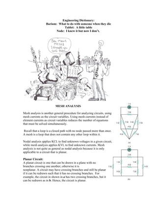
Planar Circuit:
A planar circuit is one that can be drawn in a plane with no
branches crossing one another; otherwise it is
nonplanar. A circuit may have crossing branches and still be planar
if it can be redrawn such that it has no crossing branches. For
example, the circuit in shown in a has two crossing branches, but it
can be redrawn as in b. Hence, the circuit is planar.
2. The circuit next is nonplanar, because there is no way to redraw it and avoid the branches
crossing. Nonplanar circuits can be handled using nodal analysis, but they will not be
considered in this course.
A mesh is a loop which does not contain any other loops within it.
In the circuit, paths abefa and bcdeb are meshes, but
path abcdefa is not a mesh. The current through a mesh
is known as mesh current. In mesh analysis, we are
interested in applying KVL to find the mesh currents in
a given circuit.
We will start by applying mesh analysis to planar
circuits that do not contain current sources.
In the mesh analysis of a circuit with n meshes, we take the following three steps.
1. Assign mesh currents i1, i2, . . . , in to the n meshes.
2. Apply KVL to each of the n meshes. Use Ohm’s law to express the voltages in terms
of the mesh currents.
3. Solve the resulting n simultaneous equations to get the mesh currents.
To illustrate the steps, consider the circuit shown.
The first step requires that mesh currents i1 and i2
are assigned to meshes 1 and 2.
Although a mesh current may be assigned to each
mesh in an arbitrary direction, it is conventional
to assume that each mesh current flows clockwise.
As the second step, we apply KVL to each mesh.
Applying KVL to mesh 1, we obtain
−V1 + R1i1 + R3(i1 − i2) = 0
or
(R1 + R3)i1 − R3i2 = V1
For mesh 2, applying KVL gives
3. R2i2 + V2 + R3(i2 − i1) = 0
or
−R3i1 + (R2 + R3)i2 = −V2
Note that in the first set of equations the coefficient of i1 is the sum of the resistances in
the first mesh, while the coefficient of i2 is the negative of the resistance common to
meshes 1 and 2. Now observe that the same is true in the second set of equations.
The third step is to solve for the mesh currents. Putting the equations in matrix form
yields
which can be solved to obtain the mesh currents i1 and i2. We can use any technique for
solving the simultaneous equations. Previously we learned that if a circuit has n nodes, b
branches, and l independent loops or meshes, then
l = b − n + 1.
Hence, l independent simultaneous equations are required to solve the circuit using mesh
analysis.
Notice that the branch currents are different from the mesh currents unless the mesh is
isolated. To distinguish between the two types of currents, we use i for a mesh current
and I for a branch current. The current elements I1, I2, and I3 are algebraic sums of the
mesh currents.
It is evident from the circuit above that
I1 = i1, I2 = i2, I3 = i1 − i2
Given the circuit below, solve for the loop currents i1 and i2 indicated using mesh
analysis.
4. Solution of Simultaneous Equations Using Cramer’s Rule
In circuit analysis, we often encounter a set of simultaneous equations having the form
where there are n unknown x1, x2, . . . , xn to be determined. These equations can be
written in matrix form as
This matrix equation can be put in a compact form as
AX =B
where
A is square (n x n) matrix while X and B are column matrices.
There are several methods for solving these equations. These include substitution,
Gaussian elimination, Cramer’s rule, and numerical analysis. In many cases, Cramer’s
rule can be used to solve the simultaneous equations we encounter in circuit analysis.
Cramer’s rule states that the solutions are
5. Where the Delta’s are the determinants given by
Notice that ∆ is the determinant of the matrix A and ∆k is the determinant of the matrix
formed by replacing the kth column of A by B. Cramer’s rule applies only when ∆ != 0.
When ∆ = 0, the set of equations has no unique solution, because the equations are
linearly dependent.
The value of the determinant ∆, for example, can be obtained by expanding along the first
row:
where the minor Mij is an (n − 1) × (n − 1) determinant of the matrix formed by striking
out the ith row and jth column. The value of ∆ may also be obtained by expanding along
the first column:
∆ = a11M11 − a21M21 + a31M31 + · · · + (−1)n+1
an1Mn1
We now specifically develop the formulas for calculating the determinants of 2 ×2 and 3
×3 matrices, because of their frequent occurrence. For a 2 × 2 matrix,
6. For a 3 x 3 matrix:
An alternative method of obtaining the determinant of a 3 × 3 matrix is by repeating the
first two rows and multiplying the terms diagonally as follows.
In summary:
The solution of linear simultaneous equations by Cramer’s rule boils down to finding
xk = ∆k / ∆, k = 1, 2, . . . , n
where ∆ is the determinant of matrix A and ∆k is the determinant of the matrix formed
by replacing the kth column of A by B.
Apply Mesh Analysis to find in the circuit below:
7. MESH ANALYSIS WITH CURRENT SOURCES
Applying mesh analysis to circuits containing current sources (dependent or independent)
may appear complicated. But it is actually much easier than what we encountered in the
previous section, because the presence of the current sources reduces the number of
equations. Consider the following two possible cases.
Case 1. When a current source exists only in one mesh:
Consider the circuit shown. We set i2 = −5 A and write a
mesh equation for the other mesh in the usual way, that is,
−10 + 4i1 + 6(i1 − i2) = 0 -> i1 = −2 A
Case 2: When a current source exists between two meshes:
Consider the circuit in (a), for example. We create a supermesh by excluding the current
source and any elements connected in series with it,
as shown in (b).
8. A supermesh results when two meshes have a (dependent or independent)
current source in common.
As shown in (b), we create a supermesh as the periphery of the two meshes and treat it
differently. (If a circuit has two or more supermeshes that intersect, they should be
combined to form a larger supermesh.) Why treat the supermesh differently? Because
mesh analysis applies KVL—which requires that we know the voltage across each
branch—and we do not know the voltage across a current source in advance. However, a
supermesh must satisfy KVL like any other mesh.
Therefore, applying KVL to the supermesh in (b) gives
−20 + 6i1 + 10i2 + 4i2 = 0
or
6i1 + 14i2 = 20
We apply KCL to a node in the branch where the two meshes intersect.
Applying KCL to node 0 in (a) gives
i2 = i1 + 6
Solving we get
i1 = −3.2 A, i2 = 2.8 A (3.20)
Note the following properties of a supermesh:
1. The current source in the supermesh is not completely ignored; it provides the
constraint equation necessary to solve for the mesh currents.
2. A supermesh has no current of its own.
3. A supermesh requires the application of both KVL and KCL.
Use mesh analysis to obtain i0 in the circuit below
9. 1. Identify the supermesh
2. write a mesh equation for the super mesh.
3. Write mesh equations for any addition meshes
4. Write down any equations from KCL
5. Solve
10.
11. Do Online Tutorial on Mesh Analysis
NODAL VS MESH ANALYSIS
Both nodal and mesh analyses provide a systematic way of analyzing a complex network.
Someone may ask: Given a network to be analyzed, how do we know which method is
better or more efficient?
Mesh analysis:
Networks that contain many series-connected elements, voltage sources, or supermeshes.
a circuit with fewer meshes than nodes is better analyzed using mesh analysis.
Nodal Analysis
Networks with parallel-connected elements, current sources, or supernodes are more
suitable for nodal analysis. A circuit with fewer nodes than meshes is better analyzed
using nodal analysis
The key is to select the method that results in the smaller number of equations.
The second factor is the information required. If node voltages are required, it may be
expedient to apply nodal analysis. If branch or mesh currents are required, it may be
better to use mesh analysis.
It is helpful to be familiar with both methods of analysis, for at least two reasons. First,
one method can be used to check the results from the other method, if possible. Second,
since each method has its limitations, only one method may be suitable for a particular
problem. For example, mesh analysis is the only method to use in analyzing transistor
circuits. Mesh analysis cannot easily be used to solve an op amp circuit, because there is
no direct way to obtain the voltage across the op amp itself.
For nonplanar networks, nodal analysis is the only option, because mesh analysis only
applies to planar networks. Also, nodal analysis is more amenable to solution by
computer, as it is easy to program. This allows one to analyze complicated circuits that
defy hand calculation.
A computer software package based on nodal analysis will be introduced next class.