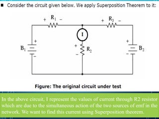
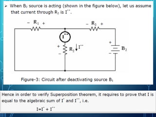
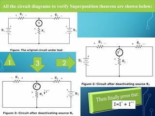
Electronic Devices and
Circuits LAB (IT-1106)
by Tajim
1
Circuit LAB 7:
Verification of
Superposition
Theorem
Experiment 7
by Tajim
2
by Tajim 3
Purpose/Objective
The aim of this experiment is-
To be familiar with the Superposition
theorem and also to verify it.
To know about its applicability.
by Tajim 4
Theory (Superposition Theorem)
This theorem may be stated as follows:
In a linear bilateral network containing more
than one generator (source of emf), the current
which flows at any point is the sum of all the
currents which would follow at that point if each
generator where considered separately and all the
other generators replaced for the time being by
resistances equal to their internal resistances.
by Tajim 5
In the above circuit, I represent the values of current through R2 resistor
which are due to the simultaneous action of the two sources of emf in the
network. We want to find this current using Superposition theorem.
by Tajim 6
Since we have two sources of power in this circuit, we will have to
calculate two sets of values for currents through R2 resistor:
* When B1 source is acting (shown in the figure below), let us assume
that current through R2 is I*.
by Tajim 7
by Tajim 8
Equipment/ Apparatus:
a) Two
regulated
variable
Power Supply
(0-30 V)
b) One
Digital
Multimeter
c) Circuit
Experiment
Board
(Breadboard)
d) Three
resistors
e) Connecting
wires
f) Cutting
tools etc.
by Tajim 9
Cautions:
1. All connections should be tight and correct.
2. Switch off the supply when not in use.
3. Reading should be taken carefully.
10
All the circuit diagrams to verify Superposition theorem are shown below:
231
by Tajim 11
Procedure:
1. Construct the circuit on the breadboard, as shown in figure-1
and observe the voltage of the two sources B1 and B2.
2. Now take the ammeter reading I.
3. Now remove the source B2 by shorting the terminals across
this source as shown in figure-2. Now take the ammeter
reading I*.
4. This time remove the source B1 by shorting the terminals
across this source as shown in figure-3. Now take the ammeter
reading I**.
5. Check I=I*+I**.
6. Repeat steps 1 to 5 by changing the value of R2.
by Tajim 12
Superposition Theorem has been verified.
LAB Report
1. LAB report must
be hand written.
2. Report on today’s
LAB must be
submitted on next
class individually.
3. LAB report will
contain: topic, brief
description of the
topic, circuit
diagram, procedure,
data table,
equipment list and
graph.
by Tajim
13
by Tajim 14

Circuit lab 7 verification of superposition theorem@taj

  • 1.
    Electronic Devices and CircuitsLAB (IT-1106) by Tajim 1
  • 2.
    Circuit LAB 7: Verificationof Superposition Theorem Experiment 7 by Tajim 2
  • 3.
    by Tajim 3 Purpose/Objective Theaim of this experiment is- To be familiar with the Superposition theorem and also to verify it. To know about its applicability.
  • 4.
    by Tajim 4 Theory(Superposition Theorem) This theorem may be stated as follows: In a linear bilateral network containing more than one generator (source of emf), the current which flows at any point is the sum of all the currents which would follow at that point if each generator where considered separately and all the other generators replaced for the time being by resistances equal to their internal resistances.
  • 5.
    by Tajim 5 Inthe above circuit, I represent the values of current through R2 resistor which are due to the simultaneous action of the two sources of emf in the network. We want to find this current using Superposition theorem.
  • 6.
    by Tajim 6 Sincewe have two sources of power in this circuit, we will have to calculate two sets of values for currents through R2 resistor: * When B1 source is acting (shown in the figure below), let us assume that current through R2 is I*.
  • 7.
  • 8.
    by Tajim 8 Equipment/Apparatus: a) Two regulated variable Power Supply (0-30 V) b) One Digital Multimeter c) Circuit Experiment Board (Breadboard) d) Three resistors e) Connecting wires f) Cutting tools etc.
  • 9.
    by Tajim 9 Cautions: 1.All connections should be tight and correct. 2. Switch off the supply when not in use. 3. Reading should be taken carefully.
  • 10.
    10 All the circuitdiagrams to verify Superposition theorem are shown below: 231
  • 11.
    by Tajim 11 Procedure: 1.Construct the circuit on the breadboard, as shown in figure-1 and observe the voltage of the two sources B1 and B2. 2. Now take the ammeter reading I. 3. Now remove the source B2 by shorting the terminals across this source as shown in figure-2. Now take the ammeter reading I*. 4. This time remove the source B1 by shorting the terminals across this source as shown in figure-3. Now take the ammeter reading I**. 5. Check I=I*+I**. 6. Repeat steps 1 to 5 by changing the value of R2.
  • 12.
    by Tajim 12 SuperpositionTheorem has been verified.
  • 13.
    LAB Report 1. LABreport must be hand written. 2. Report on today’s LAB must be submitted on next class individually. 3. LAB report will contain: topic, brief description of the topic, circuit diagram, procedure, data table, equipment list and graph. by Tajim 13
  • 14.