Power Sytem Protection Unit_5.power point presentation
1.
ANURAG ENGINEERING COLLEGE
(ANAUTONOMOUS INSTITUTION)
DEPARTMENT OF ELECTRICAL AND ELECTRONICS ENGINEERING
POWER SYSTEM PROTECTION
III B. Tech, II Semester
BY
JIBILIKAPALLY SUMAN
ASSISTANT PROFESSOR
1
30-November-2024
2.
UNIT-V
CIRCUIT BREAKERS &FUSES
2
• Introduction
• Arcing In Circuit Breakers
• Arc Interruption Theories
• Re-striking And Recovery Voltage
• Resistance Switching
• Current Chopping
• Interruption Of Capacitive Current
• Oil Circuit Breaker
• Air Blast Circuit Breakers
• SF6 Circuit Breaker
• Selection Of Circuit Breakers
• High Voltage DC Breakers
• Ratings Of Circuit Breakers
• Testing Of Circuit Breakers.
• Fuses: Introduction
• Fuse Characteristics
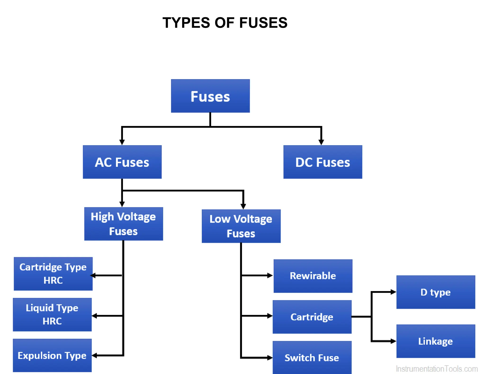
• Types Of Fuses
• Application Of HRC Fuses
• Discrimination
3.
ARCING IN CIRCUITBREAKERS
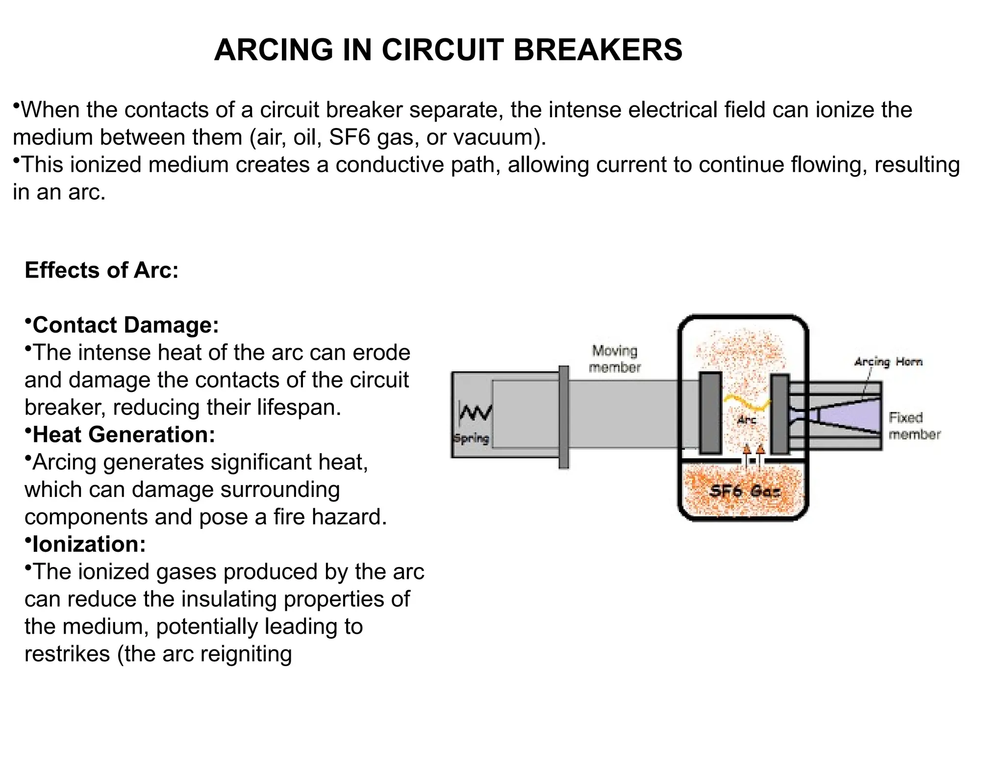
•When the contacts of a circuit breaker separate, the intense electrical field can ionize the
medium between them (air, oil, SF6 gas, or vacuum).
•This ionized medium creates a conductive path, allowing current to continue flowing, resulting
in an arc.
Effects of Arc:
•Contact Damage:
•The intense heat of the arc can erode
and damage the contacts of the circuit
breaker, reducing their lifespan.
•Heat Generation:
•Arcing generates significant heat,
which can damage surrounding
components and pose a fire hazard.
•Ionization:
•The ionized gases produced by the arc
can reduce the insulating properties of
the medium, potentially leading to
restrikes (the arc reigniting
4.
ARC INTERRUPTION
1. HighResistance Interruption:
• Concept:
• This method focuses on increasing the resistance of
the arc to such a high value that the current is forced to
zero.
• Methods of Increasing Resistance: Lengthening the arc.
• Cooling the arc.
• Reducing the cross-section of the arc.
• Splitting the arc.
2. Current Zero Interruption:
• Concept:
• This method is primarily used in AC circuit breakers.
• It takes advantage of the natural current zero that occurs in AC circuits.
• The goal is to prevent the arc from restriking after the current passes through zero.
• Process:
• In AC systems, the current reverses direction periodically, passing through zero at each
reversal.
• Circuit breakers using this method aim to increase the dielectric strength of the medium
between the contacts rapidly after a current zero.
• If the dielectric strength increases faster than the restriking voltage, the arc is
extinguished.
5.
ARC INTERRUPTION THEORIES
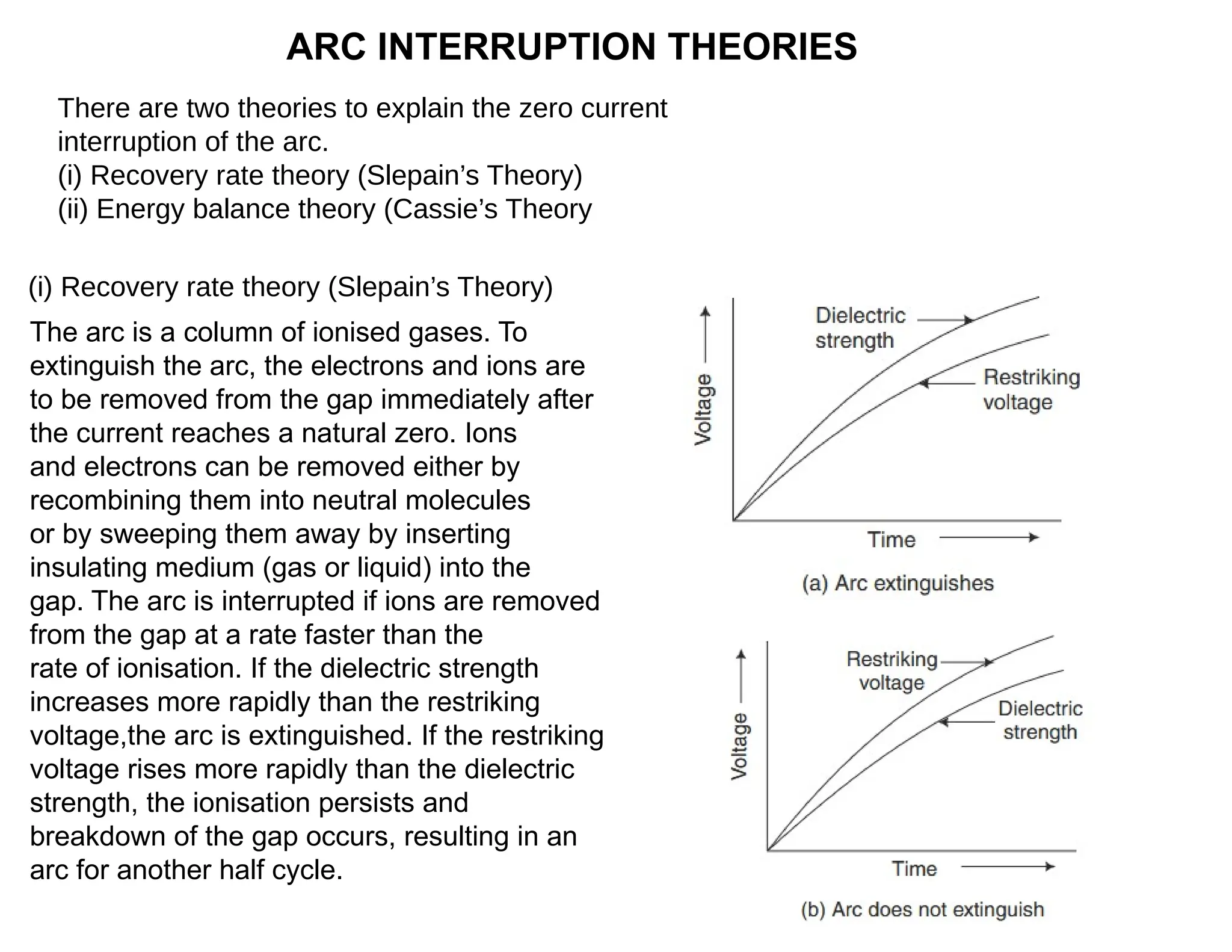
Thereare two theories to explain the zero current
interruption of the arc.
(i) Recovery rate theory (Slepain’s Theory)
(ii) Energy balance theory (Cassie’s Theory
The arc is a column of ionised gases. To
extinguish the arc, the electrons and ions are
to be removed from the gap immediately after
the current reaches a natural zero. Ions
and electrons can be removed either by
recombining them into neutral molecules
or by sweeping them away by inserting
insulating medium (gas or liquid) into the
gap. The arc is interrupted if ions are removed
from the gap at a rate faster than the
rate of ionisation. If the dielectric strength
increases more rapidly than the restriking
voltage,the arc is extinguished. If the restriking
voltage rises more rapidly than the dielectric
strength, the ionisation persists and
breakdown of the gap occurs, resulting in an
arc for another half cycle.
(i) Recovery rate theory (Slepain’s Theory)
6.
ARC INTERRUPTION THEORIES(cont..)
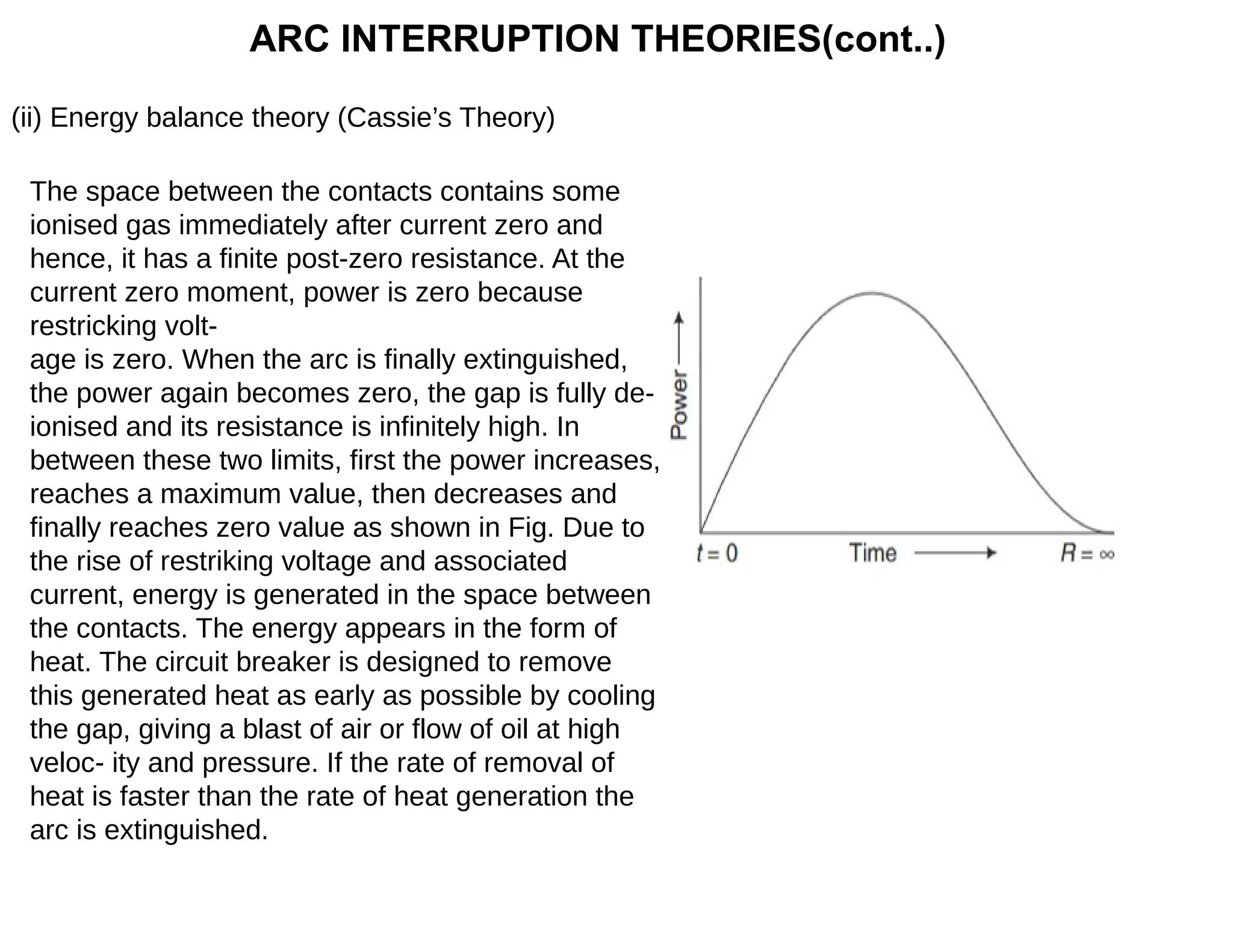
(ii)Energy balance theory (Cassie’s Theory)
The space between the contacts contains some
ionised gas immediately after current zero and
hence, it has a finite post-zero resistance. At the
current zero moment, power is zero because
restricking volt-
age is zero. When the arc is finally extinguished,
the power again becomes zero, the gap is fully de-
ionised and its resistance is infinitely high. In
between these two limits, first the power increases,
reaches a maximum value, then decreases and
finally reaches zero value as shown in Fig. Due to
the rise of restriking voltage and associated
current, energy is generated in the space between
the contacts. The energy appears in the form of
heat. The circuit breaker is designed to remove
this generated heat as early as possible by cooling
the gap, giving a blast of air or flow of oil at high
veloc- ity and pressure. If the rate of removal of
heat is faster than the rate of heat generation the
arc is extinguished.
7.
RESTRIKING VOLTAGE ANDRECOVERY VOLTAGE
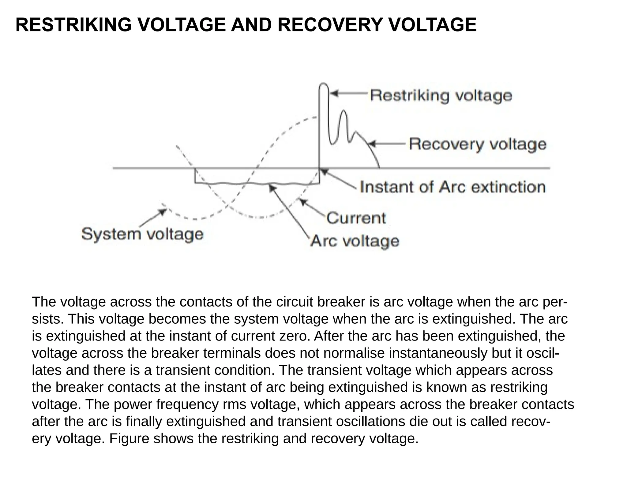
The voltage across the contacts of the circuit breaker is arc voltage when the arc per-
sists. This voltage becomes the system voltage when the arc is extinguished. The arc
is extinguished at the instant of current zero. After the arc has been extinguished, the
voltage across the breaker terminals does not normalise instantaneously but it oscil-
lates and there is a transient condition. The transient voltage which appears across
the breaker contacts at the instant of arc being extinguished is known as restriking
voltage. The power frequency rms voltage, which appears across the breaker contacts
after the arc is finally extinguished and transient oscillations die out is called recov-
ery voltage. Figure shows the restriking and recovery voltage.
8.
RESISTANCE SWITCHING
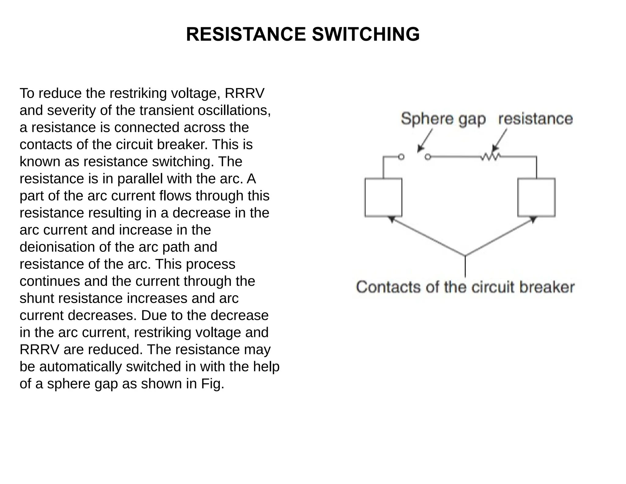
To reducethe restriking voltage, RRRV
and severity of the transient oscillations,
a resistance is connected across the
contacts of the circuit breaker. This is
known as resistance switching. The
resistance is in parallel with the arc. A
part of the arc current flows through this
resistance resulting in a decrease in the
arc current and increase in the
deionisation of the arc path and
resistance of the arc. This process
continues and the current through the
shunt resistance increases and arc
current decreases. Due to the decrease
in the arc current, restriking voltage and
RRRV are reduced. The resistance may
be automatically switched in with the help
of a sphere gap as shown in Fig.
9.
CURRENT CHOPPING
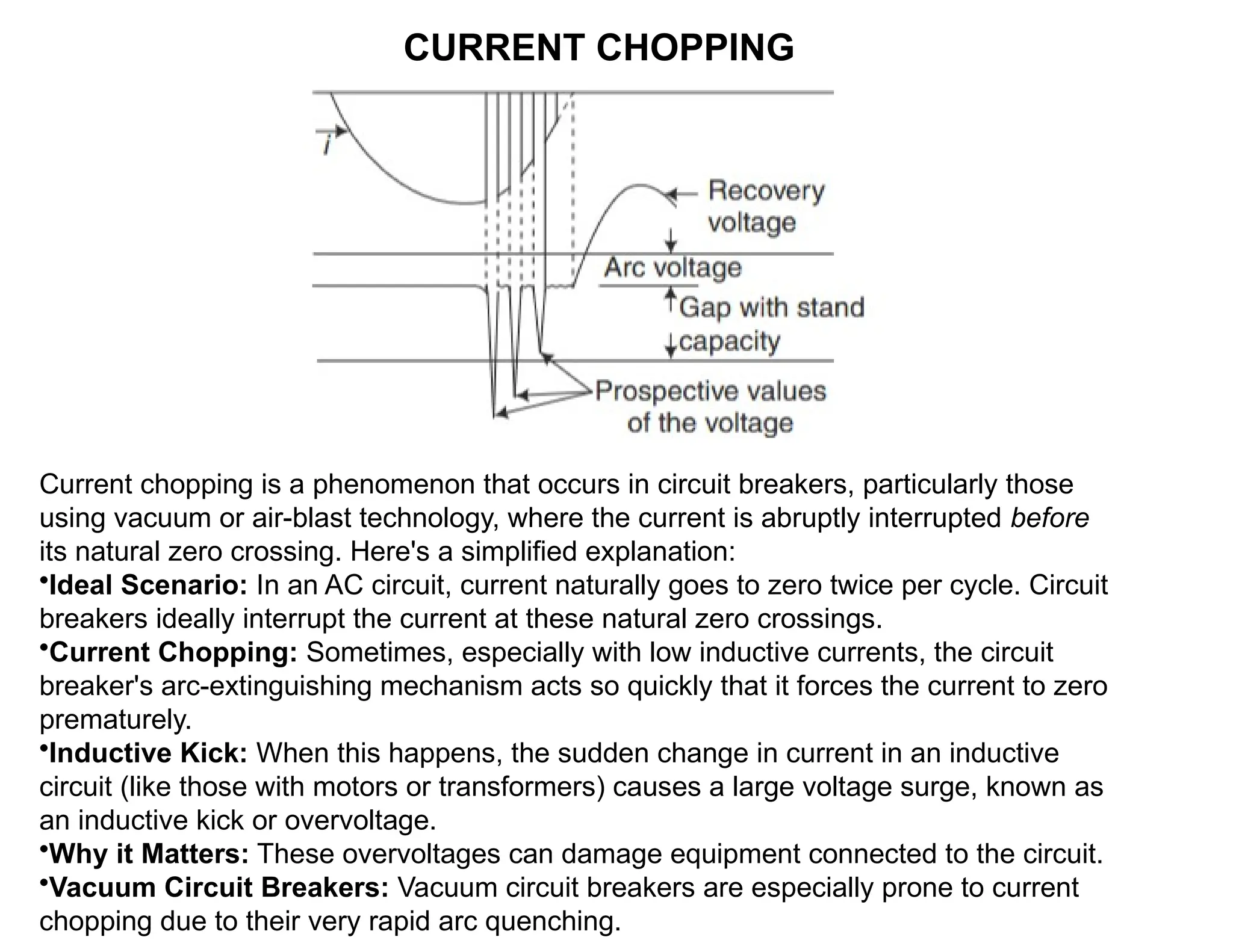
Current choppingis a phenomenon that occurs in circuit breakers, particularly those
using vacuum or air-blast technology, where the current is abruptly interrupted before
its natural zero crossing. Here's a simplified explanation:
•Ideal Scenario: In an AC circuit, current naturally goes to zero twice per cycle. Circuit
breakers ideally interrupt the current at these natural zero crossings.
•Current Chopping: Sometimes, especially with low inductive currents, the circuit
breaker's arc-extinguishing mechanism acts so quickly that it forces the current to zero
prematurely.
•Inductive Kick: When this happens, the sudden change in current in an inductive
circuit (like those with motors or transformers) causes a large voltage surge, known as
an inductive kick or overvoltage.
•Why it Matters: These overvoltages can damage equipment connected to the circuit.
•Vacuum Circuit Breakers: Vacuum circuit breakers are especially prone to current
chopping due to their very rapid arc quenching.
10.
AIR-BLAST CIRCUIT BREAKERS
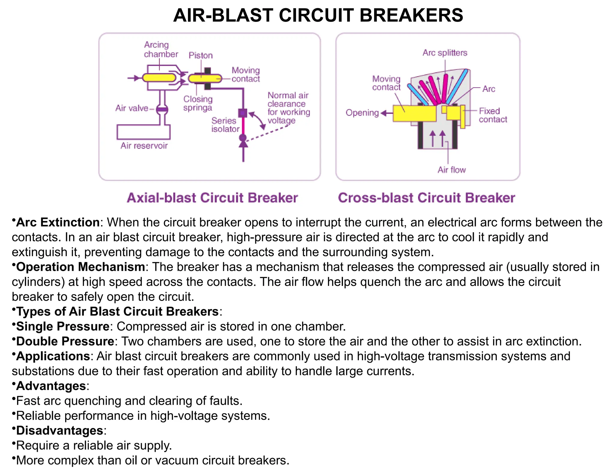
•ArcExtinction: When the circuit breaker opens to interrupt the current, an electrical arc forms between the
contacts. In an air blast circuit breaker, high-pressure air is directed at the arc to cool it rapidly and
extinguish it, preventing damage to the contacts and the surrounding system.
•Operation Mechanism: The breaker has a mechanism that releases the compressed air (usually stored in
cylinders) at high speed across the contacts. The air flow helps quench the arc and allows the circuit
breaker to safely open the circuit.
•Types of Air Blast Circuit Breakers:
•Single Pressure: Compressed air is stored in one chamber.
•Double Pressure: Two chambers are used, one to store the air and the other to assist in arc extinction.
•Applications: Air blast circuit breakers are commonly used in high-voltage transmission systems and
substations due to their fast operation and ability to handle large currents.
•Advantages:
•Fast arc quenching and clearing of faults.
•Reliable performance in high-voltage systems.
•Disadvantages:
•Require a reliable air supply.
•More complex than oil or vacuum circuit breakers.
11.
•Arc Extinction: Whenthe breaker opens due to a fault (like a short circuit), an electric arc
forms between the contacts. In an oil circuit breaker, the arc is quenched by the oil, which
cools and isolates the contacts from the arc. The oil also helps to absorb the energy from the
arc and prevents it from spreading.
•Operation Mechanism: The contacts inside the breaker are submerged in oil. When the
breaker operates, the contacts separate, and the arc is formed. The oil acts as a dielectric
medium, meaning it insulates the contacts and helps extinguish the arc by cooling and
breaking down the ionized gases.
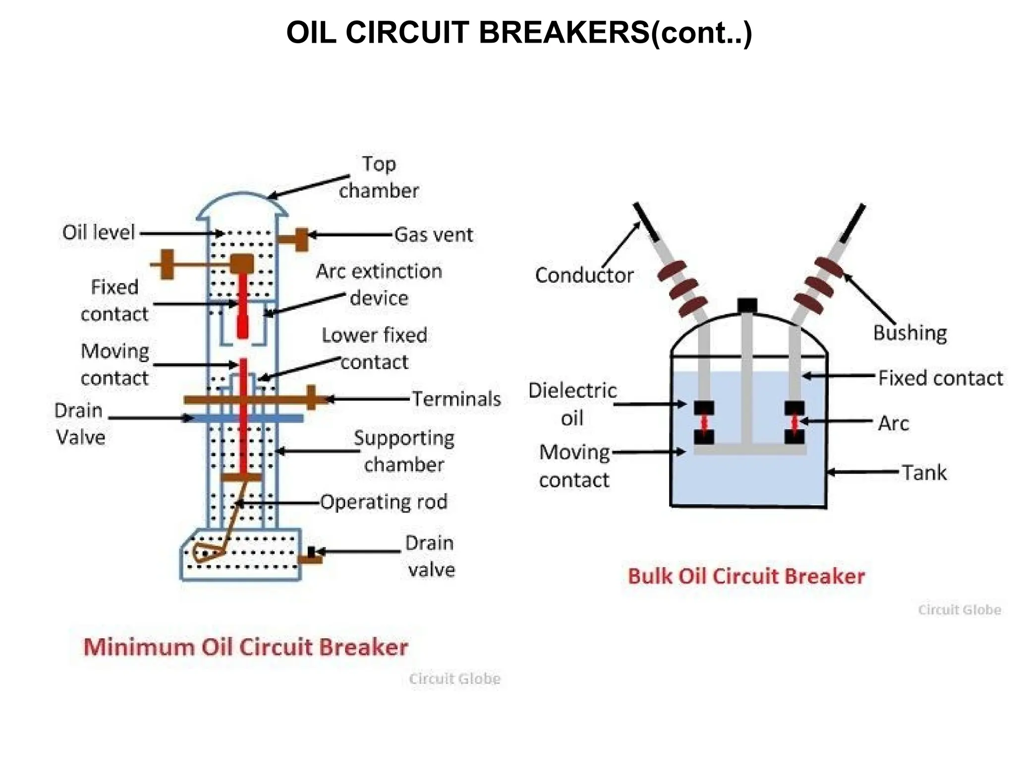
•Types of Oil Circuit Breakers:
•Bulk Oil Circuit Breaker: The entire contact mechanism is submerged in oil, and the oil
serves both as the arc-quenching medium and the insulation.
•Minimized Oil Circuit Breaker: Only a small amount of oil is used around the contacts, and
the rest of the arc-quenching is achieved using other methods like air or vacuum.
•Applications: Oil circuit breakers are typically used in electrical power transmission and
distribution systems, particularly in medium to high-voltage circuits, such as substations and
industrial power systems.
OIL CIRCUIT BREAKERS
•Advantages:
•Effective in handling high fault currents.
•Reliable and robust design for heavy-duty applications.
•Oil has high dielectric strength, allowing for good insulation.
•Disadvantages:
•Oil is flammable, which can pose a fire risk.
•Requires maintenance to ensure the oil remains clean and free from contamination.
•Larger size and more complex compared to modern circuit breakers like vacuum or SF6
breakers.
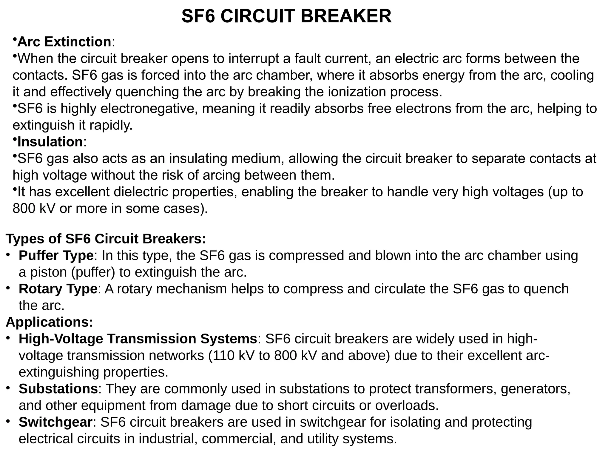
SF6 CIRCUIT BREAKER
•ArcExtinction:
•When the circuit breaker opens to interrupt a fault current, an electric arc forms between the
contacts. SF6 gas is forced into the arc chamber, where it absorbs energy from the arc, cooling
it and effectively quenching the arc by breaking the ionization process.
•SF6 is highly electronegative, meaning it readily absorbs free electrons from the arc, helping to
extinguish it rapidly.
•Insulation:
•SF6 gas also acts as an insulating medium, allowing the circuit breaker to separate contacts at
high voltage without the risk of arcing between them.
•It has excellent dielectric properties, enabling the breaker to handle very high voltages (up to
800 kV or more in some cases).
Types of SF6 Circuit Breakers:
• Puffer Type: In this type, the SF6 gas is compressed and blown into the arc chamber using
a piston (puffer) to extinguish the arc.
• Rotary Type: A rotary mechanism helps to compress and circulate the SF6 gas to quench
the arc.
Applications:
• High-Voltage Transmission Systems: SF6 circuit breakers are widely used in high-
voltage transmission networks (110 kV to 800 kV and above) due to their excellent arc-
extinguishing properties.
• Substations: They are commonly used in substations to protect transformers, generators,
and other equipment from damage due to short circuits or overloads.
• Switchgear: SF6 circuit breakers are used in switchgear for isolating and protecting
electrical circuits in industrial, commercial, and utility systems.
14.
SF6 CIRCUIT BREAKER(cont..)
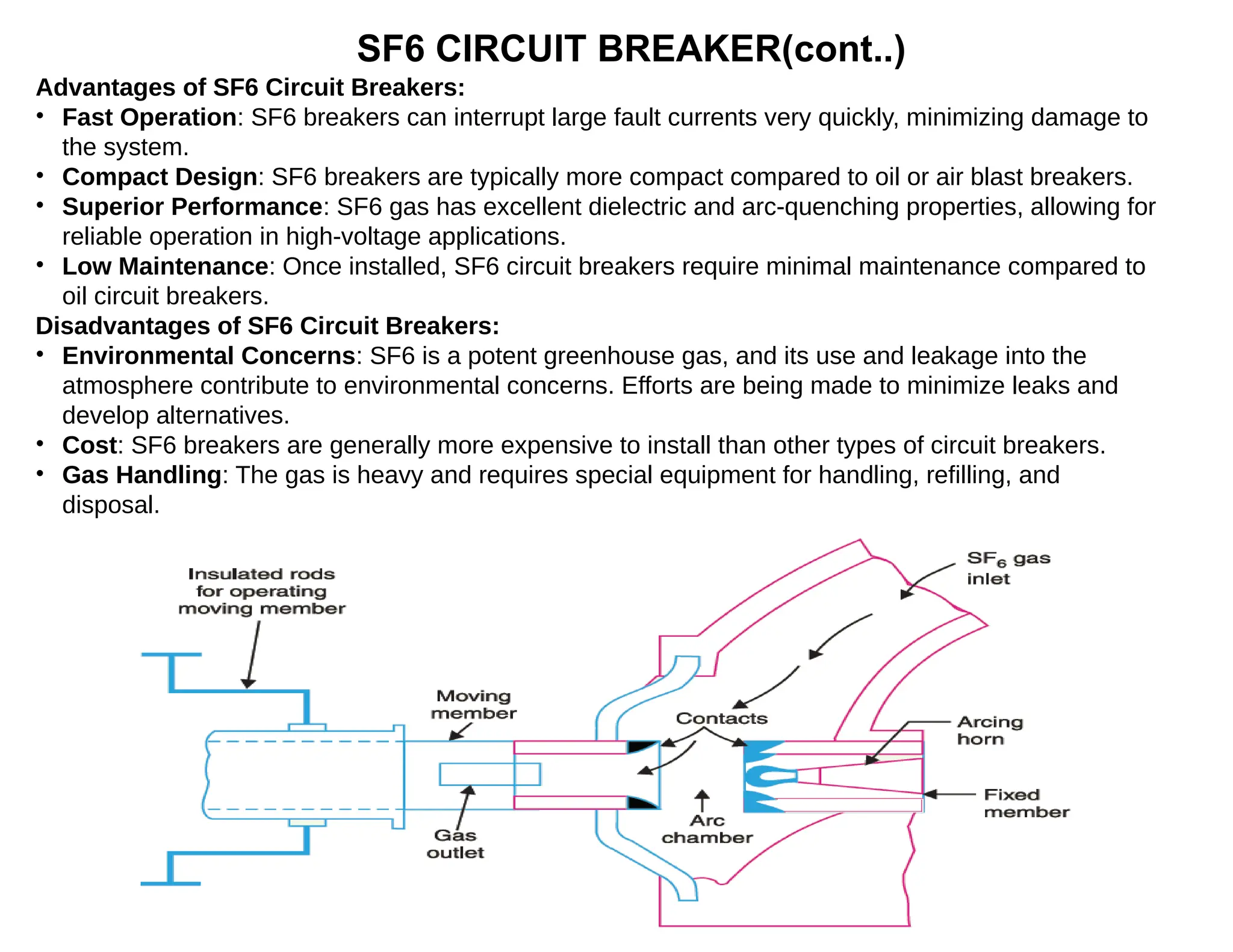
Advantagesof SF6 Circuit Breakers:
• Fast Operation: SF6 breakers can interrupt large fault currents very quickly, minimizing damage to
the system.
• Compact Design: SF6 breakers are typically more compact compared to oil or air blast breakers.
• Superior Performance: SF6 gas has excellent dielectric and arc-quenching properties, allowing for
reliable operation in high-voltage applications.
• Low Maintenance: Once installed, SF6 circuit breakers require minimal maintenance compared to
oil circuit breakers.
Disadvantages of SF6 Circuit Breakers:
• Environmental Concerns: SF6 is a potent greenhouse gas, and its use and leakage into the
atmosphere contribute to environmental concerns. Efforts are being made to minimize leaks and
develop alternatives.
• Cost: SF6 breakers are generally more expensive to install than other types of circuit breakers.
• Gas Handling: The gas is heavy and requires special equipment for handling, refilling, and
disposal.
HIGH VOLTAGE DC(HVDC) CIRCUIT BREAKERS
1. Current Interruption: In a normal AC system, circuit breakers use methods like air, oil, or gas to
extinguish the arc formed when the contacts open. In HVDC systems, the current flow is direct (DC),
which makes arc quenching more challenging. HVDC circuit breakers use solid-state components
(like semiconductors) or mechanical systems to interrupt the DC current.
2. Two Main Technologies:
1. Mechanical-based HVDC Breakers: These use a mechanical switch to physically separate the
contacts. To stop the current, the breaker uses resistors to absorb energy from the fault and
quickly open the circuit.
2. Hybrid HVDC Breakers: These combine mechanical switches and solid-state semiconductor
devices. The semiconductor devices first interrupt the current, and then the mechanical switch
disconnects the circuit completely. This hybrid system is faster and more reliable.
3. Key Role: HVDC circuit breakers are crucial for protecting the HVDC transmission lines and
equipment from damage. If there's a short circuit or fault, the breaker quickly cuts off the power,
preventing further damage to the system.
Applications:
• Long-Distance Power Transmission: HVDC systems are often used for transmitting electricity over
long distances, such as underwater cables between countries or remote areas. HVDC circuit
breakers protect these systems.
• Interconnection of Grids: HVDC is used to connect different power grids, especially in regions with
different frequencies. The circuit breaker ensures the system remains stable and safe in case of
faults.
Advantages:
• Fast Fault Clearing: HVDC circuit breakers are designed to act very quickly, minimizing damage.
• Efficient Protection for HVDC Systems: These breakers are specifically designed for DC systems,
where conventional AC circuit breakers wouldn’t work effectively.
17.
RATING OF CIRCUITBREAKERS
The ratings of circuit breakers refer to the electrical specifications that define the capabilities
and limits of a circuit breaker.
1. Voltage Rating:
• This indicates the maximum voltage that the circuit breaker can safely operate under.
2. Current Rating:
• The current rating (or nominal current) specifies the maximum continuous current the circuit
breaker can carry without tripping.
3. Interrupting Capacity (or Breaking Capacity):
• This is the maximum fault current (short-circuit current) the circuit breaker can interrupt without
being damaged.
4. Short-Circuit Protection Rating:
• This rating defines the circuit breaker's ability to handle a short-circuit fault and clear the fault
within a specified time
5. Rated Frequency:
• The frequency rating (usually 50 Hz or 60 Hz) indicates the operating frequency of the system
in which the breaker can be used.
6. Operating Mechanism Rating:
• This rating specifies the speed and reliability of the breaker’s operating mechanism to open or
close the contacts when required.
7. Insulation Rating:
• This rating indicates the electrical insulation level of the circuit breaker, meaning the voltage
the breaker can withstand in the event of a fault without breaking down or failing.
8. Endurance Rating:
• This defines the number of operations a breaker can perform without failure.
18.
TESTING OF CIRCUITBREAKERS
1. Mechanical Operation Testing:
1. Purpose: To check the mechanical components of the circuit breaker, such as the
operating mechanism, contacts, and springs.
2. Test: The breaker is manually or automatically operated to ensure it opens and closes
properly. The number of operations (on/off cycles) it can perform is tested to check its
durability.
2. Contact Resistance Testing:
1. Purpose: To ensure that the electrical contacts within the breaker are clean and making a
good connection.
2. Test: A low-resistance meter is used to measure the resistance between the contacts
when they are closed. High resistance indicates poor contact, which could lead to
overheating.
3. Insulation Resistance Testing:
1. Purpose: To check the quality of the insulation materials used in the circuit breaker.
2. Test: A high-voltage insulation tester (like a megohmmeter) is used to apply a high
voltage to the insulation and measure the resistance. A low resistance reading suggests
potential insulation failure.
4. Trip Time Testing:
1. Purpose: To verify the circuit breaker's response time during an overcurrent or short-
circuit condition.
2. Test: The breaker is subjected to a simulated fault, and the time it takes to trip (open) the
circuit is measured. This ensures it trips within the specified time for fault clearing.
5. Overload Testing:
1. Purpose: To ensure the circuit breaker will trip in the event of an overload condition.
2. Test: The breaker is subjected to a sustained overcurrent (higher than normal load) to
check if it trips within the specified delay time, protecting the system from damage.
19.
TESTING OF CIRCUITBREAKERS
6. Short-Circuit Current Interrupting Test:
1. Purpose: To verify the circuit breaker's ability to interrupt a high fault current (short-
circuit).
2. Test: The breaker is subjected to a simulated short-circuit condition to check if it can
interrupt the current without damage. This test verifies the breaker's interrupting
capacity rating.
7. Dielectric Strength Test:
3. Purpose: To check the ability of the breaker’s insulation to withstand high-voltage
conditions.
4. Test: A high-voltage is applied to the circuit breaker to ensure it does not break down
under voltage stress, verifying that it can safely insulate the current.
8. Opening and Closing Force Testing:
5. Purpose: To ensure the mechanism that opens and closes the breaker works
smoothly and with adequate force.
6. Test: The operating mechanism is tested to confirm it can open and close the
breaker reliably, with the correct force and within the required time.
9. Functional Testing of Protective Relays:
7. Purpose: To test the protective relays associated with the breaker.
8. Test: The relays that trigger the breaker during faults are tested to ensure they trip at
the correct settings, ensuring proper protection.
10. Visual Inspection:
• Purpose: To check for any visible damage, wear, or defects.
• Test: A thorough visual inspection of the circuit breaker is conducted to ensure that all
components are in good condition, with no physical damage.
20.
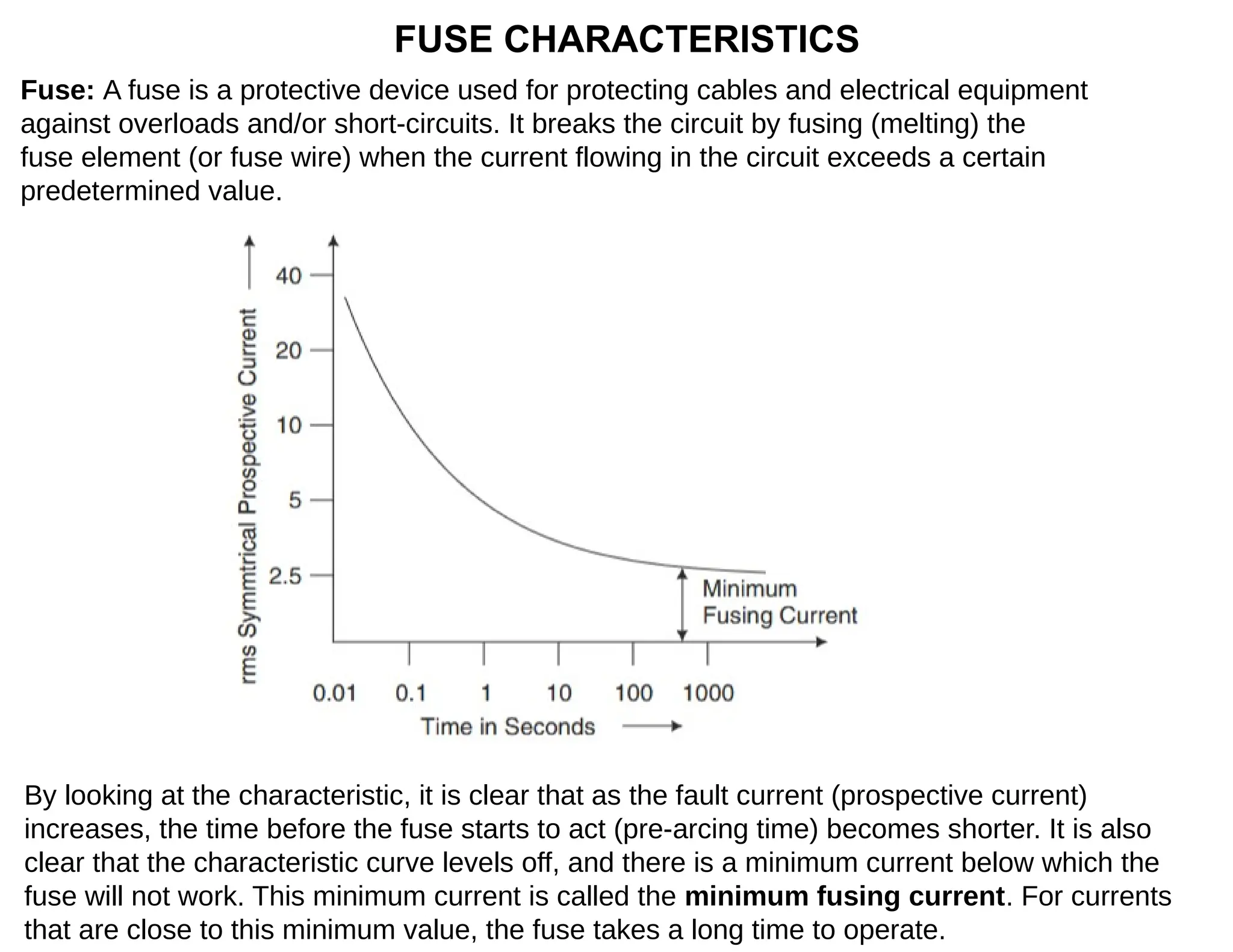
FUSE CHARACTERISTICS
Fuse: Afuse is a protective device used for protecting cables and electrical equipment
against overloads and/or short-circuits. It breaks the circuit by fusing (melting) the
fuse element (or fuse wire) when the current flowing in the circuit exceeds a certain
predetermined value.
By looking at the characteristic, it is clear that as the fault current (prospective current)
increases, the time before the fuse starts to act (pre-arcing time) becomes shorter. It is also
clear that the characteristic curve levels off, and there is a minimum current below which the
fuse will not work. This minimum current is called the minimum fusing current. For currents
that are close to this minimum value, the fuse takes a long time to operate.
APPLICATIONS OF HRCFUSES
The applications of HRC fuses arc enormous but some very important applications
are as follows.
(i) Protection of low voltage distribution systems against overloads and short-
circuits
(ii) Protection of cables
(iii) Protection of busbars
(iv) Protection of motors
(v) Protection of semiconductor devices
(vi) Back up protection to circuit breakers.
DISCRIMINATION
When two or more protective devices, e.g. two or more fuses, a fuse and a circuit
breaker, etc. are used for the protection of the same circuit, the term discrimination
concerns the correct operation of the correct device on occurrence of a fault. For
proper discrimination, there should be coordination between the protective devices.
In order to obtain proper discrimination between two adjacent fuses carrying the
same current, the pre-arcing time of the major fuse (nearer the source) must exceed
the total operating time of the minor fuse (far from the source) .
i. Discrimination between Two Fuses
ii. Discrimination between Fuses and Overcurrent Protective Devices
23.
APPLICATIONS OF HRCFUSES
The applications of HRC fuses arc enormous but some very important applications
are as follows.
(i) Protection of low voltage distribution systems against overloads and short-
circuits
(ii) Protection of cables
(iii) Protection of busbars
(iv) Protection of motors
(v) Protection of semiconductor devices
(vi) Back up protection to circuit breakers.
DISCRIMINATION
When two or more protective devices, e.g. two or more fuses, a fuse and a circuit
breaker, etc. are used for the protection of the same circuit, the term discrimination
concerns the correct operation of the correct device on occurrence of a fault. For
proper discrimination, there should be coordination between the protective devices.
In order to obtain proper discrimination between two adjacent fuses carrying the
same current, the pre-arcing time of the major fuse (nearer the source) must exceed
the total operating time of the minor fuse (far from the source) .
i. Discrimination between Two Fuses
ii. Discrimination between Fuses and Overcurrent Protective Devices
24.
DISCRIMINATION(cont..)
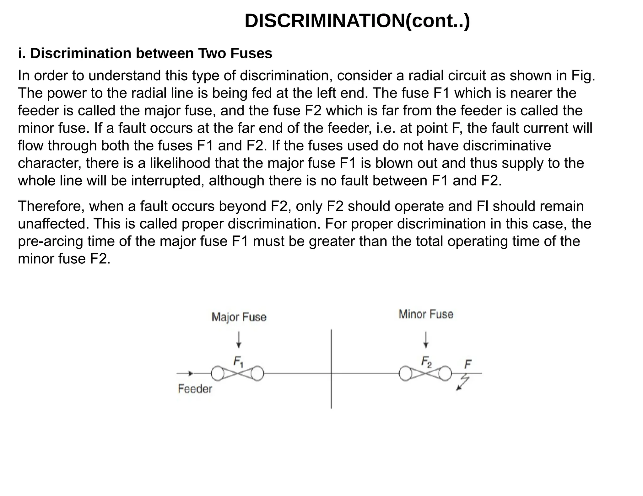
In order tounderstand this type of discrimination, consider a radial circuit as shown in Fig.
The power to the radial line is being fed at the left end. The fuse F1 which is nearer the
feeder is called the major fuse, and the fuse F2 which is far from the feeder is called the
minor fuse. If a fault occurs at the far end of the feeder, i.e. at point F, the fault current will
flow through both the fuses F1 and F2. If the fuses used do not have discriminative
character, there is a likelihood that the major fuse F1 is blown out and thus supply to the
whole line will be interrupted, although there is no fault between F1 and F2.
i. Discrimination between Two Fuses
Therefore, when a fault occurs beyond F2, only F2 should operate and Fl should remain
unaffected. This is called proper discrimination. For proper discrimination in this case, the
pre-arcing time of the major fuse F1 must be greater than the total operating time of the
minor fuse F2.
25.
DISCRIMINATION(cont..)
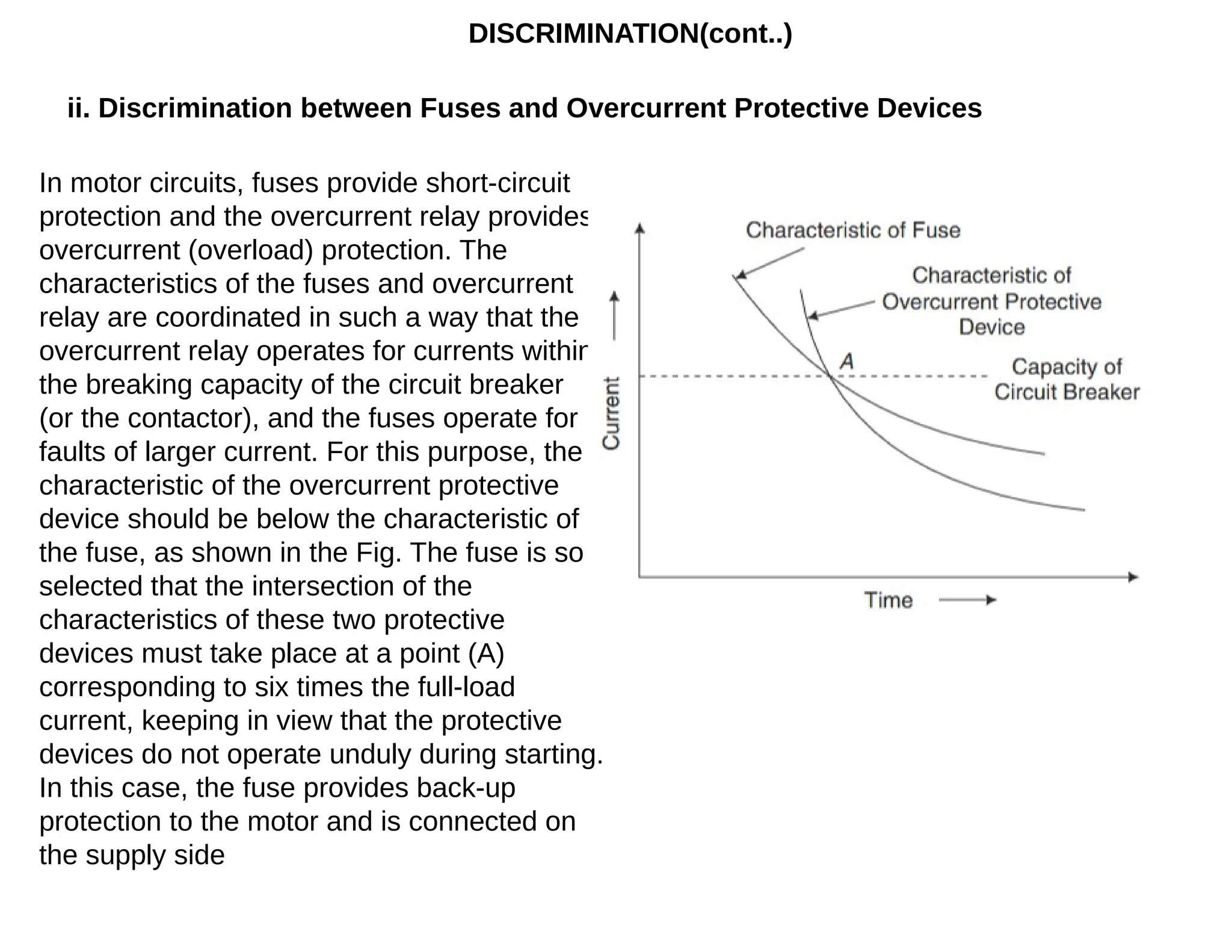
ii. Discrimination betweenFuses and Overcurrent Protective Devices
In motor circuits, fuses provide short-circuit
protection and the overcurrent relay provides
overcurrent (overload) protection. The
characteristics of the fuses and overcurrent
relay are coordinated in such a way that the
overcurrent relay operates for currents within
the breaking capacity of the circuit breaker
(or the contactor), and the fuses operate for
faults of larger current. For this purpose, the
characteristic of the overcurrent protective
device should be below the characteristic of
the fuse, as shown in the Fig. The fuse is so
selected that the intersection of the
characteristics of these two protective
devices must take place at a point (A)
corresponding to six times the full-load
current, keeping in view that the protective
devices do not operate unduly during starting.
In this case, the fuse provides back-up
protection to the motor and is connected on
the supply side