Downloaded 337 times
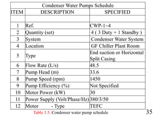
![21
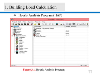
PTotal=[2L(m)×100% ×400 × 10−3(kPa/m)+FCU(kPa)
+Chiller(kPa)] eq.5
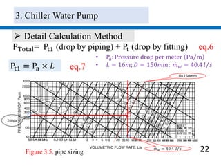
Estimation method
• Pressure drop that water across chiller is 49.8 kpa
• Pressure drop that water across FCU is 37.6 kpa
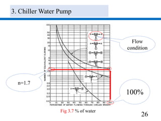
• 400 Pa m the maximum pressure drop along pipe
• L = 113m ; pipe length , 100%: Lossing a long fitting
PTotal = 2 × 113 × 2 × 400 × 10−3
kpa +
37.6 kpa + 49.8 kpa ]
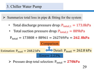
𝐏 𝐓𝐨𝐭𝐚𝐥=268.2 kPa
3. Chiller Water Pump](https://image.slidesharecdn.com/slidesengsunhor-160729083835/85/chiller-system-by-Mr-Seng-Sunhor-21-320.jpg)
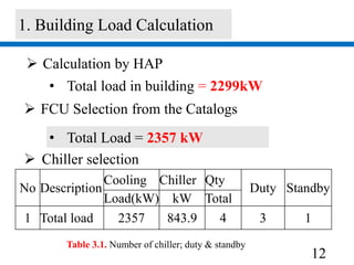
![32
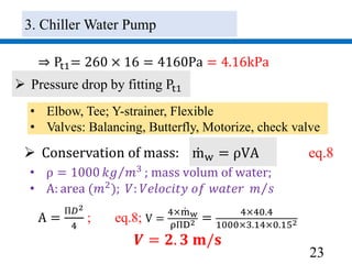
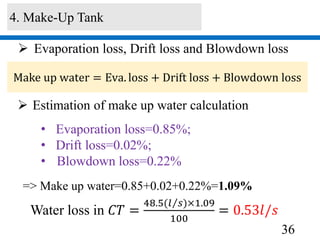
Mass flow rate: mw = 48.5 𝑙 𝑠From: eq.3
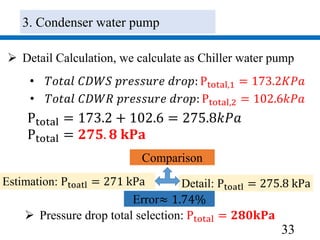
Total Pressure drop: Estimation method
PTotal = 2 × 105 × 2 × 400 × 10−3
kpa
+65 kpa + 38 kpa ]
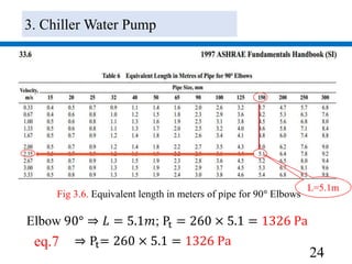
PTotal=[2L(m)×100% ×400 × 10−3(kPa/m)+CT(kPa)
+H(kPa)] eq.11
• H=3.8m=38kPa Height of CT; L=105m; Loss in CT=65kPa;
100%: loss by fitting; 2: Return and supply pipe
𝐏 𝐓𝐨𝐭𝐚𝐥 = 𝟐𝟕𝟏𝐤𝐏𝐚
3. Condenser water pump](https://image.slidesharecdn.com/slidesengsunhor-160729083835/85/chiller-system-by-Mr-Seng-Sunhor-32-320.jpg)
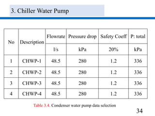


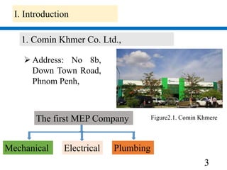
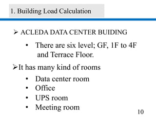
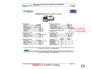
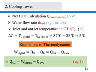
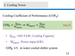
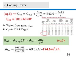
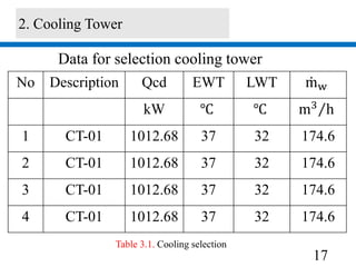
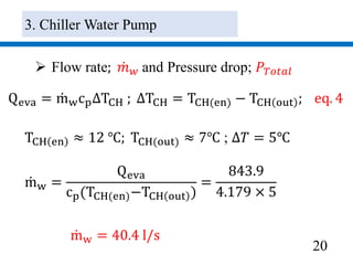
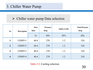
This document provides a summary of the selection process for a water cooled chiller system for Comin Khmere Co. Ltd. The following key steps are described: 1) A building load calculation using HAP software determined a total cooling load of 2357 kW. This required selecting a chiller with a 843.9 kW cooling capacity and 4 chillers total. 2) A 1012.68 kW cooling tower was selected based on the chiller condenser load and design parameters. 3) Pumps were selected to move 40.4 l/s of chilled water and 48.5 l/s of condenser water, with pressure drops of 270 kPa and 280 kPa respectively accounted